

Honeywell GENT S4 Data And Installation
Data and Installation
by Honeywell
Base
Sleeve
042bh/01
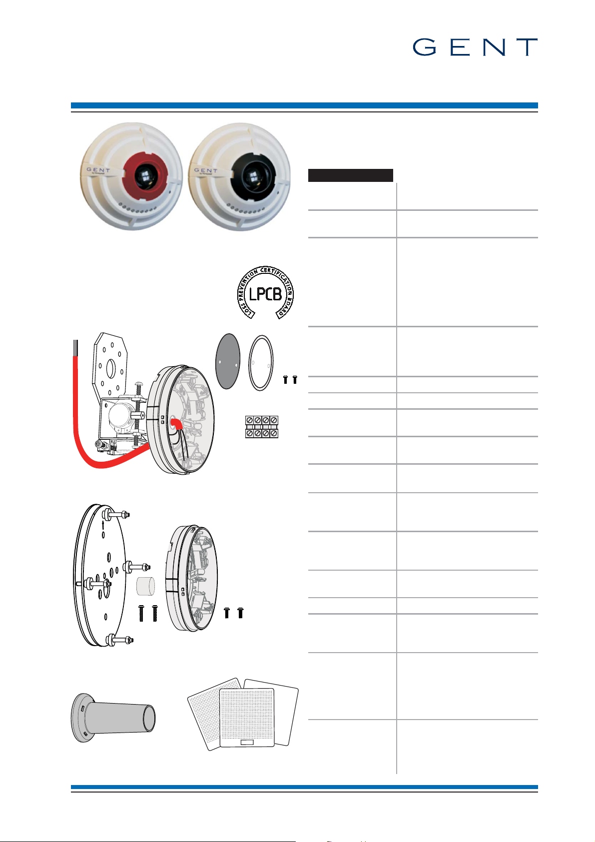
S4 Beam Sensor & brackets
(for Vigilon and Nano Systems)
The Beam Sensor pair allows the detection of
smoke over distances from2mto100m,using a
'beam transmitter' and a 'beam receiver', each
mounted on a base fixed to either bracket.
Technical Data
Standards designed to meet
Approvals LPCB Approved
Transmitter (red retainer) Receiver (black retainer)
Beam sensor pair (Transmitter & Receiver)
¨
S4-34740
Beam Transmitter only
¨
S4-34741
Beam Receiver only
¨
S4-34742
¨
Angle bracket with base
S4-34741-01
¨
Parallel bracket with base
S4-34741-03
¨
Light Shield (5 per pack) Test Cards
S4-34741-99 S4-34741-50
Overall
assembled
dimensions in mm
Assembled weight
(approximate)
Enclosure ABS
Colour (Sensor) RAL9010
Storage
temperature
Ambient operating
temperature
Relative Humidity
(Non condensing)
Emission BS EN61000-6-3: 2007 EMC
Immunity BS EN50130-4: 1996 +
Ingress Protection
(estimated)
Operating voltage 35-41V
Indicators Two Red and Seven Green
EN54-17 : 2005
(section 4.8)
data:
Compatible
Backward compatibility
is possible, refer to
your supplier
EN54 : Part 12 : 2002
EN54 : Part 17 : 2005
STATES 0, 1, 2 and 3
Transmitter or receiver:
Æ 117xd54
Angle bracket with base:
h145xw106xd130
Parallel bracket with base:
Æ 152xd27
Light shield: Æ 50x75
Transmitter or receiver:105g
Angle bracket + base: 620g
Parallel bracket + base: 600g
Light shield: 14g
-20 to +70ºC
-10 to +50°C
up to 95%
Temperature +5 to +45°C
for residential, commercial &
light Industry.
A1:1998 +A2 2003
for alarm systems
IP30
IP20 mounted on bracket
LEDs visible at 500LUX
ambient light levels 5m
max 42V IC max 0.4A
V
nom 40V IS max 1A
V
min 24V IL max 20mA
V
SO max 16V VSO min 8V
V
C max 0.130W
Z
Vigilon : MCC ³ V4.41 / V3.96
LPC ³ V4.39 / V3.96
Nano : MC ³ V1.39
LD ³ V1.03
4188-969 issue 3_Part 1_07-11_S4 Beam & brackets 1
Data and Installation S4 Beam Sensor & brackets
IR Beam
(invisible)
Solid Wall
Floor level
IR Beam projection
Solid Walls
Plan view (flat ceiling)
Receiver
Receiver
Transmitter
Transmitter
Transmitter
Receiver
Shelves and Storage boxes
Solid Wall
Floor level
Ceiling
Building structure support
Solid Wall
Floor level
Ceiling
Ventilation duct
0.3m - 0.6m
15m
> 0.15m
Metal Ceiling
Unistrut
25m maximum
15m
2m to 100m maximum
1m minimum
7m maximum
Solid Walls
Plan view (flat ceiling)
Receiver
Receiver
Transmitter
Transmitter
15m
3m max.
>0.5m
Receiver
Transmitter
Receiver
Transmitter
Receiver
Transmitter
Metal beam
Solid Wall
2.5 m
17.5 m width
17.5 m width covered by one beam sensor pair within 600mm
vertical of the apex, using the extra coverage of 25% given
by the roof angle of 25
o
25
o
1.25 m
10 m mounting
height
20 m
600mm
Calculated from
12.5% of 10m
mounting height
Seven beam sensor
pair required
at this height
2.5 m calculated from
twice 12.5% of 10m
mounting height
ATRIUM
Side view (flat ceiling)
Obstructions
Cladding panels / Plaster board
Transmitter
Transmitter
Receiver
Glass Atrium
Heat Source
Receiver
Horizon
Sunlight or Strong light source
Horizon
Sunlight or Strong light source
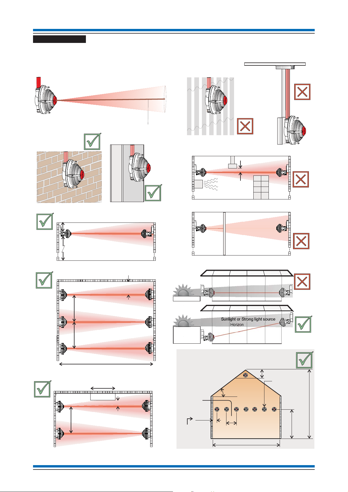
Do's and Dont's
A general guidance on Do's and Dont's is illustrated here, however for full information on siting beam sensor
pair refer to BS5839 Part 1.
2 4188-969 issue 3_Part 1_07-11_S4 Beam & brackets
S4 Beam Sensor & brackets Data and Installation
EM2
OUT5
IN4
C3
L1
0V
L2
470 W
10 KW
Input
Beam Transmitter base
FIRE
14115-08
or any suitable
keyswitch
O
I
Active
O
I
Normal
O
I
L1
0V
L2
0V
L1 (1)
0V (4)
0V(2)
L2 (3)
EARTH(5)
The numbers in brackets
refer to alternative cable
sleeve markings which may
be used to denote wires.
Metal box
Earth
Cable from the sensor base
Loop - In cable
Loop - Out cable
Angle bracket with base
Metal box
mounted on
a solid wall
Beam Sensor
Keyswitch wiring if used
The Test Keyswitch
connects to terminals
EM2 and C3 in the
base.
Test Keyswitch
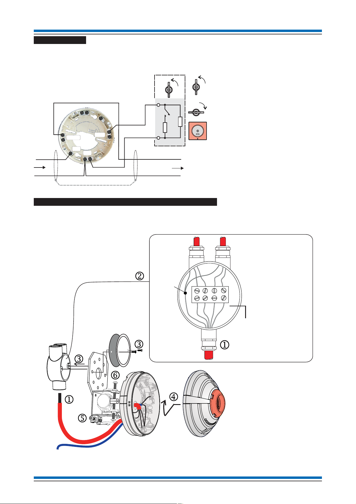
A test keyswitch unit can be connected to the 'beam transmitter' to facilitate simulation of a test fire condition.
The test keyswitch function is supported on Vigilon system only. The keyswitch unit is required to have a
series resistor of value 470W coupled with an end-of-line 10KW resistor wired as illustrated below.
There is a maximum cable length
limit of 15 metres from the 'beam
transmitter' base to the external
Keyswitch Unit.
A keyswitch input at the 'beam
transmitter' must be enabled
during commissioning.
The wiring is monitored for open
and short circuit failure.
On operating the keyswitch it will
cause a ramp down signal to
generate a test fire condition.
How to install an Angle bracket and fit a Beam sensor
The installation of the angle bracket and beam sensor are illustrated by steps j to o. Note steps n and
o require setting of adjusters for sensor to face the opposite sensor assembly, which is normally done
during commissioning.
4188-969 issue 3_Part 1_07-11_S4 Beam & brackets 3
Data and Installation S4 Beam Sensor & brackets
by Honeywell
At the end of their useful life, the packaging,
product and batteries should be disposed of
via a suitable recycling centre and in
accordance with national or local legislation.
Do not dispose of with your normal household waste.
Do not burn.
WEEE Directive:
At the end of their useful life, the packaging,
product and batteries should be
disposed of via a suitable recycling centre.
0832
Gent by Honeywell
Hamilton Industrial Park,
140 Waterside Road,
Leicester LE5 1TN, UK
Product EC Certification
No. of Conformity No.
S4-34741 0832-CPD-1365
S4-34742 0832-CPD-1365
ARROW
Fixed plate
Adjustable plate
Adjuster
Bush
Lock nut
Bush
Spring
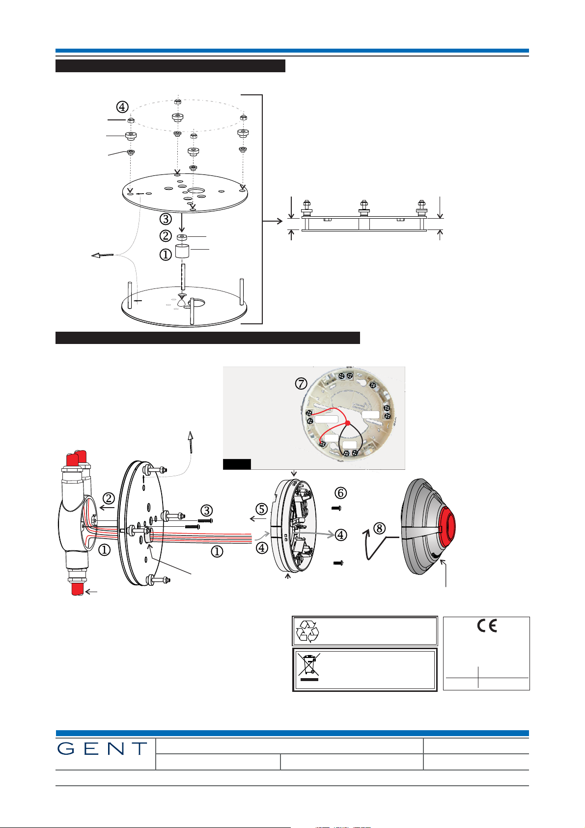
8mm
8mm
Ensure the adjusters are set to provide an 8mm
gap all around between the adjustable and fixed plates.
THIS WAY UP
Pre-assembled
Parallel bracket
Metal
box
Beam Sensor
Base
EM2
OUT5
IN4
C3
L1
0V
L2
LOOP IN
LOOP OUT
Loop Cable
In - Out
Test Keyswitch wiring if used
The Test Keyswitch
connects to EM2 and
C3, see page 3.
Sleeve
Ensure the base is mounted to the bracket such
that the Beam sensor LEDs can be seen from floor level.
How to pre-assemble the parallel bracket
The parallel bracket may be pre-assembled as illustrated by steps j to m.
How to install a Parallel Bracket and fit a Beam sensor
The installation of the parallel bracket and beam sensor are illustrated by steps j to q.
Further information about this product can be found in Part 2
of this document available on Gent Expert website.
Gent by Honeywell reserves the right to revise this publication from time to time and make changes to the content hereof without
obligation to notify any person of such revisions of changes.
4 4188-969 issue 3_Part 1_07-11_S4 Beam & brackets
Hamilton Industrial Park, Waterside Road, Leicester LE5 1TN, UK Website: www.gent.co.uk
Telephone: +44 (0) 116 246 2000 Tech. Support: www.gentexpert.co.uk Fax (UK): +44 (0)116 246 2300
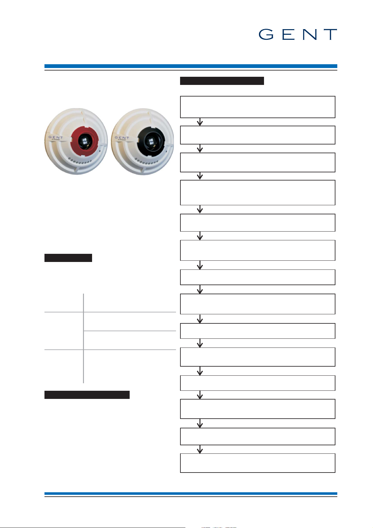
Commissioning information
by Honeywell
Light shield
A light shield is only required to be fitted onto a beam receiver where
direct sunlight or strong light is likely to fall in the path of the ‘beam
receiver’. Where necessary fit the light shield.
Find Beam
Finding the device address of the ‘beam transmitter’ and
‘beam receiver’ on the loop.
Normal indications
Check the operational indications given by the red LEDs on the
beam sensor.
Laser tool
Read the instructions supplied with the recommended laser tool
and roughly align the beam sensor using the tool.
Compatibility
Check the control panel in the system has compatible software for
the S4 beam sensors installed on its loop circuit.
Brackets
If necessary, check the method of adjusting the parallel and angle
brackets.
Select a STATE
Program the required Beam sensor STATE, the factory default
is STATE 0.
Alignment indications
Interpreting the alignment indications given at a beam device.
Align beam sensor pair
Align the ‘beam transmitter’ with ‘beam receiver’.
Time averages
Reading the time averages during beam sensor alignment.
Gain and STATE
Check the Beam STATE selected is applicable.
Check the Gain value after alignment is within the distance range.
Tests
Perform tests on the installed beam sensor pair.
Commissioning tool
Where required, configure the monitored input and working
indication features.
Beam STATES
Determine which Beam sensor STATE is required.
S4 Beam Sensor & brackets
(for Vigilon and Nano Systems)
This document describes how to adjust the
beam sensor using adjusters on the angle or
parallel bracket, align beam sensor pairs and
test the installation.
Transmitter (red retainer) Receiver (black retainer)
A beam sensor pair consist of a:
'beam transmitter' that can be identified by
¨
a red lens retainer and a
'beam receiver' that can be identified by a
¨
black lens retainer.
each sensor is fitted onto a base that is a
¨
part of an angle or parallel bracket.
Compatibility
The S4 Beam Sensor pair are compatible for
use in Vigilon and Nano systems having the
following panel firmware.
Commissioning checks
Control
Panel
having card and firmware
Vigilon Main Controller Card
³ V4.41 / V3.96
Loop Processor Card
Nano Main Controller
³ V4.39 / V3.96
³ V1.39
Loop Driver
³ V1.03
Backward Compatibility
An S4 Beam sensor pair can be converted to
be a BACKWARD COMPATIBLE Beam
Sensor pair.
The conversion is done using a Programming
base interface for S4 beam sensor pair, see
section headed 'Backward Compatibility'.
4188-968 issue 4_Part 2_07-12_S4 mains interface 1
Commissioning information S4 Beam Sensor & brackets
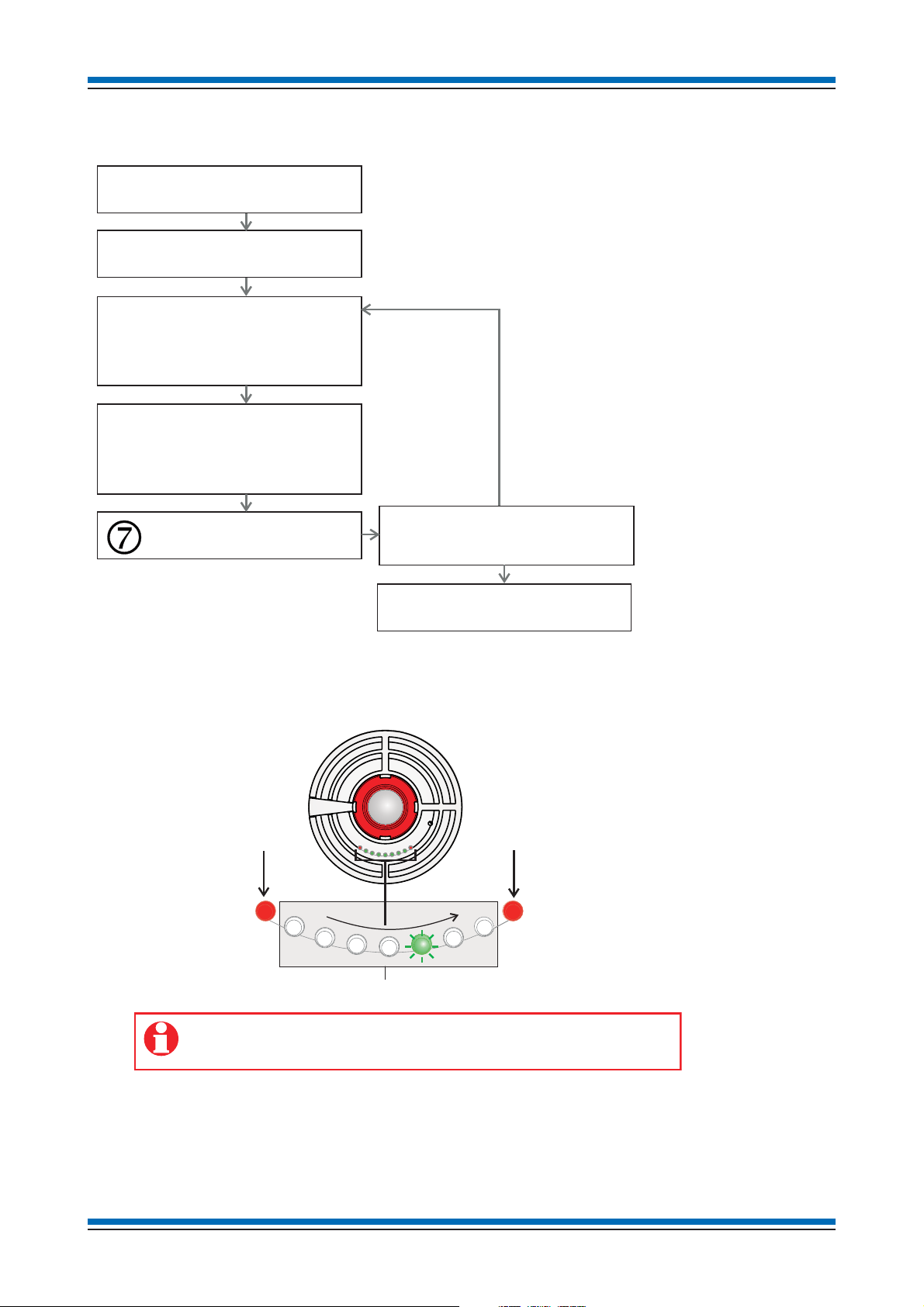
[Align] the ‘beam sensor pair’
[Autogain] the ‘beam receiver’
Adjust the ‘beam transmitter’
[Autogain] at the device
Adjust the ‘beam receiver’
[Autogain] the ‘beam receiver’
at the panel.
Check Gain value matches the distance
as stated on page 13.
Repeat the process if required.
k
j
l
m
n
o
[Autogain] at the device
Move on to align the next beam
sensor pair
This Red LED illuminates during
alignment to indicate the sensor
has reached Saturation.
This Red LED illuminates during
alignment to indicate a low level
signal, which means the sensor
is Out of Specification.
These Green LEDs are lit during the alignment process to indicate the ADC bit level.
140 bits
180 bits
Less than 140 bits
More than 180 bits
Make adjustments in the X axis and Y axis, using adjusters on the beam sensor
bracket to let the highest Green LED to illuminate. The LEDs update
every 2 seconds, so make small adjustments and wait for the indication to refresh.
How to align a Beam Sensor pair
Overall process to align Beam sensor pair
During the alignment process all the LEDs on the 'beam transmitter' and 'beam receiver' act as a simple level
meter to indicate the ADC bit level. An increase in level causes the intensity of the particular LED to
increase, until the level is enough to turn on the next LED to the right.
The illumination of red LEDs on a beam sensor will indicate the level is either too low or too high and it is
important to carry out a sensor [Auto Gain] after adjustment of the bracket.
2 4188-968 issue 4_Part 2_07-12_S4 mains interface
S4 Beam Sensor & brackets Commissioning information
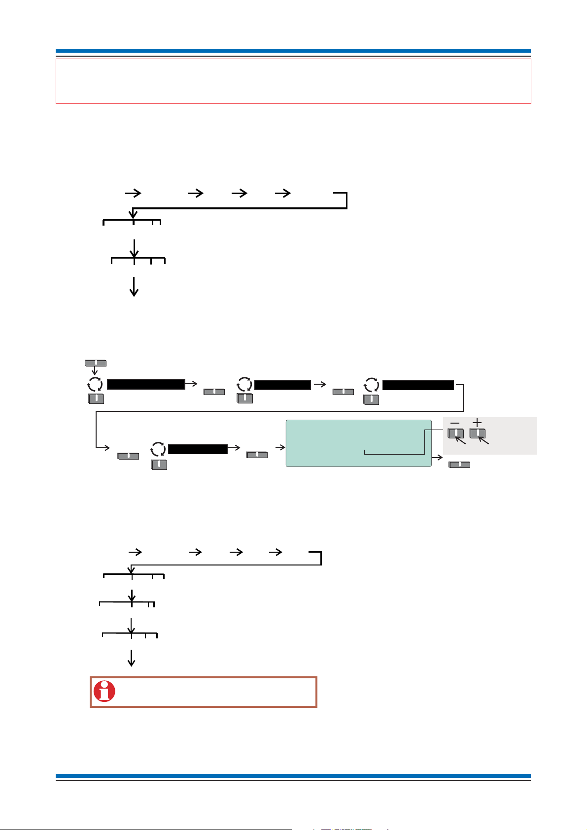
{}
Params
1-207
[Device]
{}
Params
1-207
[Loop]
{}
Params
1-8
[C] [Q]
[E]
[Align]
<etc>
[Test/Eng]
[UserCode]
[Loop]
Enter the ‘ device addressBeam receiver’
Enter the on which the Beam sensor pair are installedloop number
The Alignment function is activated.
Enter the ‘ device addressBeam transmitter’
The alignment function will timeout after 1 hour.
Select Select
Engineering
Menu
Beams >
Select
16:15 Mon 16/02/09
Warning! Selecting this option will
initiate the beam autogain procedure.
Enter Beam RX Address [ 1]
Accept Quit
Autogain
Select
Accept
To scroll the range 1-127
Loop >
Enter the ‘beam
receiver’ device
address
Enter the on which
the ‘beam receiver’ is installed
loop number
[AutoGain]
[Loop]
{}
Params
1-207
{}
Params
1-8
[C] [Q]
[E]
<etc>
[Test/Eng]
[UserCode]
[Loop]
Enter the ‘beam receiver’ device address
Enter the on which the ‘beam receiver’ is installedloop number
An ‘Auto Gain’ is carried out at the ‘beam receiver’.
"
On first power up of the system having beam sensors a light indication of 'Sensor out of Specification' is
given at each beam sensor, with the left most Red LED on the beam sensor lit.
jAssuming the beam sensor pair are in rough alignment at the control panel activate the [Autogain]
function on the 'beam receiver' of the beam sensor pair to be commissioned. You will need to know the
device address of the 'beam receiver' and the loop number on which it resides.
Procedure for Vigilon panel (Access level 3)
Procedure for Nano panel (Access level 4)
kUsing the options in [Test/Eng] menu put the required beam pair into [Align] mode.
Procedure for Vigilon panel (Access level 3)
4188-968 issue 4_Part 2_07-12_S4 mains interface 3
 Loading...