

Page 1
Introduction
The Galaxy V-Plex Interface supports 128 sensors and 64 outputs. If required additional V-pex interfaces can
be connected to the RS485 line.
The interface connects directly to the Galaxy RS485 communication bus, and is programmed directly from a
standard Galaxy keypad connected to the module.
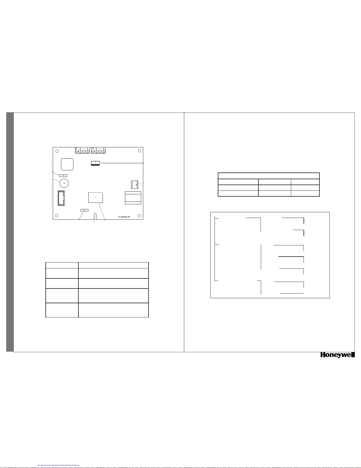
Galaxy V-Plex Interface Layout
Connecting the V-Plex Interface
Connect the V-Plex Interface terminals as in V-Plex Connections, below:
Honeywell Security - Newhouse Industrial Estate - Motherwell - Lanarkshire - ML1 6SB - UK Part No.II1-0077 Rev. 2.01 p. 1
V-Plex Interface - English
V-Plex bus
connection
Processor
Retaining slot
Alternative programming
keypad socket
Tamper
bypass
switch
Programming
switch
SW3
SW4
PL 2
SW2
PANE L
KEYPAD
PROGRAMMING HEADER
PL1
Tamper
switch
V-Plex Interface Connected to
+
+12 V (at control panel, keypad or remote
power supply)
-
0V or ground (at control panel, keypad or
remote power supply)
A
To the A terminal of the previous module on the
line (or the control panel if the V-Plex Interface
is the fi rst module on the line)
B
To the B terminal of the previous module on the
line (or the control panel if the V-Plex Interface
is the fi rst module on the line)
V-Plex Connections for Panel & Keypad Terminals
V-Plex Tamper
If the Galaxy panel is not in Engineer Mode, removing the lid of the enclosure will cause a tamper alarm.
Switch SW2 can be used to temporarily bypass the tamper switch. Closing SW3 will bypass the tamper
protection.
Galaxy V-Plex Interface Programming Menu
Programming
Entering Programming Mode
To enter V-Plex Interface Programming Mode:
Ensure that the Galaxy panel is in Engineer Mode.
1.
Address a keypad as 0 and connect it to the keypad terminals of the V-Plex Interface.2.
Close the programming switch (SW4).3.
The V-Plex Interface is now in Programming Mode and the keypad displays a language selection option.
Language Selection
LANGUAGE SELECT
00=ENGLISH 03=ITALIANO 06=ESPANOL
01=NEDERLANDS 04=FRANCAIS 07=CZECH
02=SVENSK 05=FLEMISH 08=SLOVAK
10 = PROG MODULE
20 = PROG ZONES 001-128
30 = PROG OUTPUTS 001-154
2 = Device ID
Enter Number
A=YES
B=NO
11 = Cold start
12 = RIO Address 00-15
0 = Disable
1 = Enable
1 = Type
0 = Serial Poll
1 = Dip SW Poll
2 = Loop No
1 = Loop 1
2 = Loop 2
3 = Device ID
1 = Manual
2 = Self learn
1 = Type
0 = Serial Poll
1 = Dip SW Poll
OPTION 10 - PROG MODULE
OPTION 11 - Cold Start
This option loses all programming by restoring the Non-Volatile Memory to the default values.
OPTION 12 - RIO Address
This option allows the programming of up to 16 simulated RIO modules. The RIO address must be
enabled to allow zone and output programming of its zone and output addresses. An enabled address is
shown as ■; a disabled address is shown as □.
After a cold start, or with a new module, all addresses are disabled.
Page 2
Honeywell Security - Newhouse Industrial Estate - Motherwell - Lanarkshire - ML1 6SB - UK Part No. II1-0077 Rev. 2.01 p. 2
Deleting a Detector or an Output
Select option 20=PROG ZONES to delete a detector or 30=PROG OUTPUTS to delete an output.1.
Select the address2.
Select the device ID option.3.
For detectors only, select the Manual option4.
Assign the value 05.
Press Enter 6.
The device is deleted.
OPTION 30 - PROGRAMMABLE OUTPUTS
Select the desired output address.
1.
From the Type menu, select Serial or DIP Switch Poll device type.2.
Select the device ID and enter the serial number. The serial number is on a sticker either inside the 3.
module enclosure or attached to the PCB.
The V-plex detectors are assigned a specifi c RIO zone address.
Select the desired zone address.
1.
From the Type menu, select serial or DIP device.2.
From the Loop menu, select the loop number. If the loop selected is not free, you cannot programme3.
the device serial number.
Most detectors use loop 1. Please see the installation instructions of the detector being used.
From the Device menu select Manual or Self Learn. Detectors that have DIP switches or both DIP
4.
switches and serial numbers must use the manual option.
The manual option allows the 2-digit zone address for DIP devices or the 7-digit numbers of 5.
serial devices to be entered.
The Self Learn option allows the V-Plex interface to record the serial detector’s serial number by
allowing one minute to record the detector by opening and closing its tamper. The 7-digit serial number
is displayed.
Note: The control panel will recognize V-Plex zone values as resistance preset value of 1K Fault
(BAL).
OPTION 20 - PROG ZONE
Exiting Programming Mode
Open the programming switch and disconnect the keypad from the V-Plex Interface.1.
Exit from Engineer Mode at the Galaxy panel.2.
DECLARATION OF CONFORMITY
SPECIFICATIONS
Physical
Weight (Boxed): 270g approximately.
Dimensions (Boxed mm): 150 wide x 162 high x 39 deep for enclosure Type B
Operating temperature range: -10° C to +55° C
Humidity: Relative Humidity 25% to 75%
Electrical
Operating voltage range: 10.5V to 14.5V
Module current draw: 75mA typical, 85mA max
Max V-Plex bus current available: 128mA
An additional power supply should be used if the current draw of the V-plex devices exceeds the V-plex
interface capacity
EN50131-1 & EN50131-3 Security Grade 2,
Environmental Class II
Independently tested by Telefi cation b v
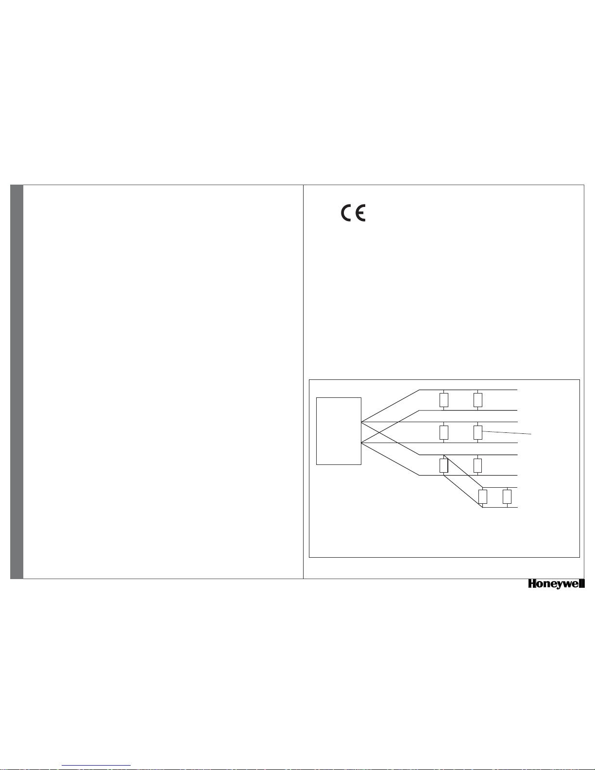
V-PLEX INTERFACE
+
-
+
+
+
+
-
-
-
-
V-Plex devices
Star wiring is supported with a maximum branch length of 457m and
combined maximum length 1400 meters (18AWG UTP cable current draw 64mA)
It is recommended that devices programmed as Manual and Self learn are not installed
on the same V-Plex interface
V-Plex W iring Diagram
V-Plex Interface - English
 Loading...