

Page 1
FR124
Einbauanleitung • Installation instructions • Notice de montage • Installatiehandleiding • Istruzioni di montaggio
Instrucciones de montaje • Asennusohje • Installasjoninstruksjon • Monteringsanvisning • Инструкция по монтажу
Instrukcja montażu • Návod na montáž • Beépítési útmutató • Montaj kılavuzu • Instrucţiuni de montaj • Montážny návod
Інструкція з монтажу
Anleitung zum späteren Gebrauch aufbewahren!
Keep instructions for later use!
Conserver la notice pour usage ultérieur!
Handleiding bewaren voor later gebruik!
Conservare le istruzioni per uso successivo!
Guardar estas Instrucciones para su uso futuro!
Säilytä ohje vastaisen varalle!
Ta vare på bruksanvisningen for senere bruk!
Förvara bruksanvisningen för senare användning!
Сохранить инструкцию для последующего
пользования!
Zachowa instrukcj do pózniejszego wykorzystania!
Návod uschovejte pro pozdější použití!
Az útmutatót őrizze meg a későbbi használatra!
K1lavuzu ileride kullanmak üzere saklay1n!
Pstraci instrucciunile pentru o utilizare ulterioar!
Návod uchovajte pre neskoršie použitie!
Зберігати інструкцію для подальшого
використання!
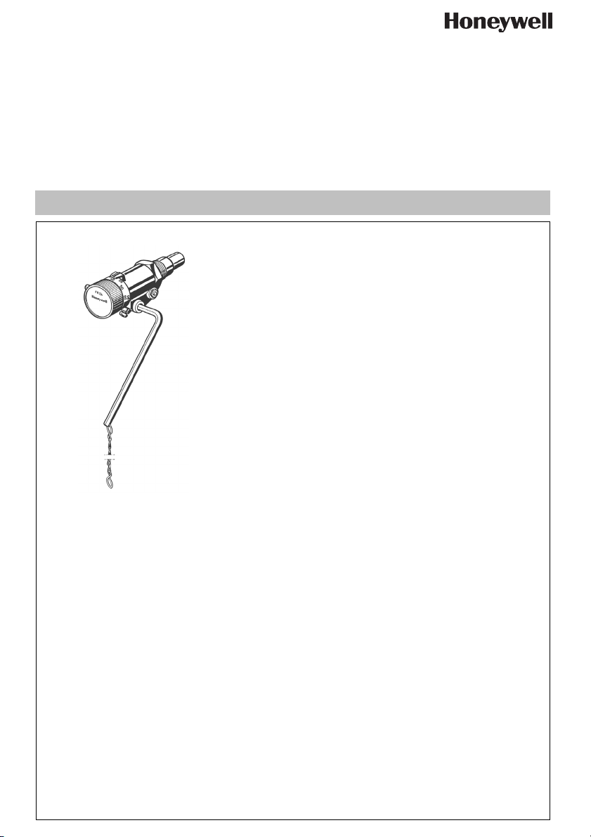
Feuerungsregler
Combustion regulator
Régulateur de combustion
Stookregelaar
Regolatore del bruciatore
Regulador de combustión
Paloilman säädin
Forbrenningsregulator
EB-FR124 Rev. A
Eldningsregulator
Регулятор горения
Regulator paleniska
Regulátor spalování
Tüzelésszabályozó
Ateşleme regülatörü
Regulator de aprindere
Regulátor spaľovania
Регулятор спалювання
Page 2

D
1. Sicherheitshinweise
1. Beachten Sie die Einbauanleitung.
2. Benutzen Sie das Gerät
• bestimmungsgemäß
• in einwandfreiem Zustand
• sicherheits- und gefahrenbewusst.
3. Beachten Sie, dass das Gerät ausschließlich für
den in dieser Einbauanleitung genannten Verwendungsbereich bestimmt ist. Eine andere oder
darüber hinausgehende Benutzung gilt als nicht
bestimmungsgemäß.
4. Beachten Sie, dass alle Montage-, Inbetriebnahme,
Wartungs- und Justagearbeiten nur durch autorisierte Fachkräfte ausgeführt werden dürfen.
5. Lassen Sie Störungen, welche die Sicherheit beeinträchtigen können, sofort beseitigen.
2. Funktionsbeschreibung
Der Feuerungsregler dient dazu, die Luftzufuhr für die
Verbrennung zu regeln. Der eingebaute Thermostat
misst die Temperatur im Wärmeerzeuger und regelt in
Abhängigkeit davon über einen Hebel mit Kette die
Luftzufuhr des feststoffbeheizten Heizkessels durch
Öffnen bzw. Schließen der Luftklappe.
3. Verwendung
Für Heizungsanlagen nach DIN 4751 mit Feststoffund Wechselbrandkesseln
Der Feuerungsregler FR124 darf insbesondere in
folgenden Fällen nicht verwendet werden:
• Explosionsgefährdete Umgebung
Bei Betrieb in explosionsgefährdeten Bereichen
kann Funkenbildung zu Verpuffungen, Brand oder
Explosionen führen.
4. Technische Daten
Sollwertbereich 30...90 °C
zulässige Fühlertemperaturmax. 115 °C
Umgebungstemperatur max. 70 °C am Schaltkopf
Anschlussgröße G 3/4"
Kettenlänge 1,2 m
Kettenbelastung 100...600 g
Tauchrohrlänge 53 mm
5. Lieferumfang
Der Feuerungsregler besteht aus:
• Gehäuse
• Einstellknopf
• Tauchhülse
• Hebelstange
• Kette
• Dehnstoff-Thermostat
• Rückstellfeder
6. Varianten
FR124-3/4A = Normalausführung
7. Montage
7.1 Einbauhinweise
• Einbaulage horizontal oder vertikal
• Feuerungsregler im Wasserkreislauf des Kessels
einbauen
• Nur in die dafür vorgesehene Gewindemuffe
einbauen
7.2 Montageanleitung
1. Gewinde mit einem Hanf- oder Teflonband
abdichten.
3
2. Tauchrohr (Gewinde G
Kessels einschrauben
3. Hebelstange fixieren
4. Kette an der Hebelstange und der Zuluftklappe
befestigen
o Die Kette hängt frei und die Hebelstange bewegt
sich beim Drehen des Einstellknopfs frei
/4) in die Gewindemuffe des
8. Inbetriebnahme
8.1 Feuerungsregler kalibrieren
1. Kessel bei manuell geöffneter Zuluftklappe
anheizen
2. Einstellknopf des Feuerungsreglers auf „60“
einstellen
3. Wenn die Wassertemperatur 60 °C erreicht hat und
stabil bleibt, die Länge der Kette so anpassen, dass
die Tür 2 mm offen bleibt.
MU1H-1515GE23 R0709 2 Honeywell GmbH
Page 3
D
9. Störungen / Fehlersuche
Störung Ursache Behebung
Temperatur liegt im stabilisierten
Betriebszustand unter dem eingestellten Wert.
Temperatur liegt im stabilisierten
Betriebszustand über dem eingestellten Wert.
Zu wenig Luftzufuhr Kette verkürzen
Weitere Einflüsse, z. B. zu viel Asche
im Kessel.
Unabhängig vom FR124 alle
weiteren Einflüsse überprüfen, z. B.
Brennstoff- und Aschenmenge, Lage
der Beiluftklappe, Trägheit des
Kessels und des gesamten
Heizungssystems
Zu viel Luftzufuhr Kette verlängern
Zuluftklappe klemmt und geht nicht zuZuluftklappe ölen
Weitere Einflüsse, z. B. zu viel Asche
im Kessel.
Unabhängig vom FR124 alle
weiteren Einflüsse überprüfen, z. B.
Brennstoff- und Aschenmenge, Lage
der Beiluftklappe, Trägheit des
Kessels und des gesamten
Heizungssystems
Sonstige Störungen Technische Kundenberatung
anrufen
10. Entsorgung
• Gehäuse und Einstellknopf aus hochwertigem
Kunststoff
• Tauchhülse aus Messing
• Hebelstange aus Stahl, verzinkt
• Kette aus Stahl, verzinkt
Honeywell GmbH 3 MU1H-1515GE23 R0709
Page 4

GB
1. Safety Guidelines
1. Follow the installation instructions.
2. Use the appliance
• according to its intended use
• in good condition
• with due regard to safety and risk of danger.
3. Note that the appliance is exclusively for use in the
applications detailed in these installation instructions. Any other use will not be considered to comply
with requirements and would invalidate the
warranty.
4. Please take note that any assembly, commissioning, servicing and adjustment work may only be
carried out by authorized persons.
5. Immediately rectify any malfunctions which may
influence safety.
2. Functional description
The Combustion Regulator controls combustion by
adjusting the supply of air to a boiler. The intergral thermostat measures the temperature in the heat generator and in relationship to the temperature regulates a
lever with chain linkage to control the air inlet to the
solid fuel boiler by opening or closing the air flap.
3. Application
For solid fuel and multi-fuel heating installations to DIN
4751
The FR124 Combustion Regulator may in particular
not be used in the following cases:
• Explosive environments. Sparks can lead to deflagration, fire or explosions during operating in explosive areas.
4. Technical data
Setting range 30...90 °C
Permissible sensor
temperature
Ambient air temperature max. 70 °C on adjuster
Connection size T 3/4"
Chain length 1.2 m
Chain load 100...600 g
Immersion tube length 53 mm
max. 115 °C
knob
5. Scope of delivery
The FR124 Combustion Regulator consists of:
• Housing
• Adjuster knob
• Immersion pocket
• Lever rod
• Chain
• Wax thermostat
• Return spring
6. Options
FR124-3/4A = Standard version
7. Assembly
7.1 Installations Guidelines
• Horizontal or vertical installation
• Install Combustion Regulator in the water cycle of
the boiler
• Only install it in the screw socket intended for this
purpose
7.2 Assembly instructions
1. Seal threaded joint with hemp or Teflon tape.
3
2. Screw immersion tube (thread T
threaded socket of the boiler
3. Secure the lever rod
4. Secure chain to the lever rod and the inlet air flap
o The chain hangs free and the lever rod moves
freely when the adjuster knob is turned
/4) into the
8. Commissioning
8.1 Calibrating the Combustion Regulator
1. Heat up the boiler with manually opened inlet air flap
2. Set the adjuster knob on the Combustion Regulator
to "60"
3. Once the water temperature has reached and maintained 60 °C adjust the chain length so that door 2
remains open.
MU1H-1515GE23 R0709 4 Honeywell GmbH
Page 5
GB
9. Troubleshooting
Problem Cause Remedy
Temperature during stabilised operation is below the set value.
Too little inlet air Shorten chain
Other influences, e.g. too much ash
in the boiler.
Irrespective of the FR124, check all
other influences, e.g. fuel and ash
quantities, position of the admixed air
flap, boiler inertia and the entire
heating system
Temperature during stabilised operation is above the set value.
Too much inlet air Extend chain
Inlet air flap is jammed and does not
Oil inlet air flap
shut
Other influences, e.g. too much ash
in the boiler.
Irrespective of the FR124, check all
other influences, e.g. fuel and ash
quantities, position of the admixed air
flap, boiler inertia and the entire
heating system
Other faults Call Technical Customer Service
10. Disposal
• High-quality synthetic material housing and adjuster
knob
• Brass sensor pocket
• Galvanized steel lever rod
• Galvanized steel chain
Honeywell GmbH 5 MU1H-1515GE23 R0709
Page 6

F
1. Consignes de sécurité
1. Suivre les indications de la notice de montage.
2. En ce qui concerne l'utilisation de l'appareil
• Utiliser cet appareil conformément aux données du
constructeur
• Maintenir l'appareil en parfait état
• Respectez les consignes de sécurité
3. Il faut noter que cet équipement ne peut être mis en
oeuvre que pour les conditions d'utilisation mentionnées dans cette notice. Toute autre utilisation, ou
le non respect des conditions normales d'utilisation,
serait considérée comme non conforme.
4. Observer que tous les travaux de montage, de mise
en service, d'entretien et de réglage ne pourront
être effectués que par des spécialistes autorisés.
5. Prendre des mesures immédiates en cas d'anomalies mettant en cause la sécurité.
2. Description fonctionnelle
Le régulateur de combustion sert à réguler l'alimentation d'air pour la combustion. Le thermostat intégré
mesure la température dans le générateur de chaleur
et régule en conséquence via un levier avec une
chaîne l'alimentation d'air de la chaudière chauffée
avec le combustible solide en ouvrant ou en fermant le
clapet d'air.
3. Mise en oeuvre
Pour installations de chauffage selon DIN 4751 avec
chaudières à combustible solide et chaudières mixtes
Le régulateur de combustion FR124 ne doit pas être
utilisé en particulier dans les cas suivants:
• Environnements à risques d'explosion En cas
d'exploitation dans des environnements à risques
d'explosion, la production d'étincelles peut conduire
à des déflagrations, un incendie ou des explosions.
4. Caractéristiques
Plage de valeurs nominales
Température de sonde
admise
Température ambiante max. 70 °C sur le dispositif
Dimensions de
raccordement
Longueur de chaîne 1,2 m
Charge sur la chaîne 100...600 g
Longueur du tube plongeur53 mm
30...90 °C
max. 115 °C
de commutation
G 3/4"
5. Contenu de la livraison
Le régulateur de combustion est composé de:
• Boîtier
• Bouton de réglage
• Doigt de gant
• Barre de levier
• Chaîne
• Thermostat à matière dilatable
• Ressort de rappel
6. Variantes
FR124-3/4A = Version normale
7. Montage
7.1 Dispositions à prendre
• Position de montage horizontale ou verticale
• Monter le régulateur de combustion dans le circuit
d'eau de la chaudière
• Montage uniquement dans le manchon fileté prévu
à cet effet
7.2 Instructions de montage
1. Étanchéifier le filetage avec une bande de chanvre
ou de téflon.
3
2. Visser le tube plongeur (Filetage G
manchon fileté de la chaudière
3. Fixer la barre de levier
4. Fixer la chaîne à la barre du levier et au clapet
d'alimentation d'air
o La chaîne pend librement et la barre de levier
bouge librement quand on tourne le bouton de
réglage
/4) dans le
8. Mise en service
8.1 Calibrer le régulateur de combustion
1. Allumer la chaudière, le clapet d'alimentation d'air
étant ouvert manuellement
2. Régler le bouton de réglage du régulateur de
combustion sur „60“
3. Quand la température de l'eau a atteint 60°C et est
stabilisée, ajuster la longueur de la chaîne de sorte
que la porte reste ouverte de 2 mm.
MU1H-1515GE23 R0709 6 Honeywell GmbH
Page 7

F
9. Défaut / recherche de panne
Panne Cause Remède
La température à l'état d'exploitation
stabilisé est à un niveau inférieurà la
valeur réglée.
Alimentation en air insuffisante Raccourcir la chaîne
Autres influences, par ex. trop de
cendres dans la chaudière
Vérifier toutes les autres influences
indépendamment du FR124, par ex.
la quantité de combustible et de
cendres, la position du clapet d'air
d'infiltration, l'inertie de la chaudière
et de tout le système de chauffage.
La température à l'état d'exploitation
stabilisé est à un niveau supérieurà
la valeur réglée.
Alimentation en air trop importante Rallonger la chaîne
Le clapet d'alimentation d'air se
Huiler le clapet d'alimentation en air
bloque et ne se ferme pas
Autres influences, par ex. trop de
cendres dans la chaudière
Vérifier toutes les autres influences
indépendamment du FR124, par ex.
la quantité de combustible et de
cendres, la position du clapet d'air
d'infiltration, l'inertie de la chaudière
et de tout le système de chauffage.
Autres dysfonctionnements Appeler le service d'assistance tech-
nique
10. Matériel en fin de vie
• Corps et bouton de réglage en matière plastique de
haute qualité
• Douille plongeuse en laiton
• Barre de levier en acier zingué
• Chaîne en acier zingué
Honeywell GmbH 7 MU1H-1515GE23 R0709
Page 8

NL
1. Veiligheidsvoorschriften
1. Lees de installatiehandleiding goed door.
2. Gebruik het apparaat
• waarvoor het is bestemd
• in goede toestand
• met aandacht voor de veiligheid en mogelijke
gevaren
3. Let op dat het apparaat uitsluitend bestemd is voor
het toepassingsgebied dat in de installatiehandleiding wordt aangegeven. Elk ander gebruik geldt als
niet in overeenstemming met het doel waarvoor het
is bestemd, waardoor de garantie vervalt.
4. Houd er rekening mee dat alle montage-, ingebruikname-, onderhouds- en aanpassingswerkzaamheden alleen mogen worden uitgevoerd door
gekwalificeerde vakmensen.
5. Laat storingen die de veiligheid kunnen aantasten
direct verhelpen.
2. Functiebeschrijving
De stookregelaar dient ertoe om de luchttoevoer voor
de verbranding te regelen. De ingebouwde thermostaat meet de temperatuur in de warmteopwekker en
regelt afhankelijk daarvan via een hefboom met ketting
de luchttoevoer van de met vaste brandstof
verwarmde verwarmingsketel door de luchtklep te
openen resp. te sluiten.
3. Gebruik
Voor verwarmingsinstallaties volgens DIN 4751 met
vaste brandstof- en combiketels
De stookregelaar FR124 mag met name in de
volgende gevallen niet gebruikt worden:
• Explosieve omgeving Bij bedrijf in explosieve omgevingen kan vonkvorming ontploffingen, brand of
explosies veroorzaken.
4. Technische gegevens
Gewenste waardebereik 30...90 °C
Toegelaten voelertemperatuur max. 115 °C
Omgevingstemperatuur max. 70 °C aan de
schakelkop
Aansluitmaat G 3/4"
Kettinglengte 1,2 m
Kettingbelasting 100...600 g
Dompelbuislengte 53 mm
5. Leveringsomvang
De stookregelaar bestaat uit:
• Behuizing
• Instelknop
• Dompelhuls
• Hefboomstang
• Ketting
• Thermostaat met uitzettend materiaal
• Terugzetveer
6. Modellen
FR124-3/4A = normale uitvoering
7. Montage
7.1 Montage-instructies
• Inbouwpositie horizontaal of verticaal
• Stookregelaar inbouwen in de waterkringloop van
de ketel.
• Alleen inbouwen in de daartoe voorziene schroefdraadmof.
7.2 Montagehandleiding
1. Schroefdraad afdichten met een hennep-of teflonband.
3
2. Dompelbuis (schroefdraad G
draadmof van de ketel schroeven.
3. Hefboomstang vastzetten.
4. Ketting bevestigen aan de hefboomstang en de klep
voor de luchttoevoer.
o De ketting hangt vrij en de hefboomstang beweegt
zich bij het draaien van de instelknop vrij.
/4) in de schroef-
8. Ingebruikstelling
8.1 Stookregelaar kalibreren
1. Ketel bij manueel geopende klep voor de luchttoevoer opwarmen.
2. Instelknop van de stookregelaar instellen op „60“.
3. Als de watertemperatuur 60 °C heeft bereikt en
stabiel blijft de lengte van de ketting zo aanpassen,
dat de deur 2 mm open blijft.
MU1H-1515GE23 R0709 8 Honeywell GmbH
Page 9
NL
9. Storing / Opzoeken en verhelpen van fouten
Storing Oorzaak Oplossing
Temperatuur ligt in de gestabiliseerde operationele toestand onder de
ingestelde waarde.
Te weinig luchttoevoer Ketting verkorten.
Andere invloeden, bijv. te veel as in
de ketel
Onafhankelijk van de FR124 alle
hoeveelheid brandstof en as, positie
van de klep voor extra lucht, traagheid van de ketel en van het hele
verwarmingssysteem.
Temperatuur ligt in de gestabiliseerde operationele toestand boven de
ingestelde waarde.
Te veel luchttoevoer Ketting verlengen.
Klep voor luchttoevoer klemt en gaat
Klep voor luchttoevoer oliën.
niet dicht.
Andere invloeden, bijv. te veel as in
de ketel
Onafhankelijk van de FR124 alle
hoeveelheid brandstof en as, positie
van de klep voor extra lucht, traagheid van de ketel en van het hele
verwarmingssysteem.
Andere storingen Technische klantenservice opbellen
10. Recyclage
• Behuizing en instelknop van hoogwaardig kunststof
• Dompelhuls van messing
• Hefboomstang van staal, verzinkt
• Ketting van staal, verzinkt
Honeywell GmbH 9 MU1H-1515GE23 R0709
Page 10

I
1. Avvertenze di sicurezza
1. Rispettare le istruzioni di montaggio.
2. Utilizzare l'apparecchio
• secondo la destinazione d'uso
• in uno stato perfetto
• in modo sicuro e consapevoli dei pericoli connessi
3. Si prega di considerare che l'apparecchio è realizzato esclusivamente per il settore d'impiego riportato nelle presenti istruzioni d'uso. Un uso differente
o diverso da quello previsto è da considerarsi improprio.
4. Osservare che tutti i lavori di montaggio, di messa in
funzione, di manutenzione e di regolazione devono
essere eseguiti soltanto da tecnici specializzati e
autorizzati.
5. I guasti che potrebbero compromettere la sicurezza
devono essere risolti immediatamente.
2. Descrizione del funzionamento
Il regolatore del bruciatore serve a regolare l'alimentazione di aria necessaria per la combustione. Il termostato incorporato misura la temperatura nel generatore
di calore e, in base ad essa, regola la quantità di aria
verso la caldaia a combustibile solido aprendo o chiudendo la valvola per mezzo di una leva con catena.
3. Uso
Per impianti di riscaldamento secondo DIN 4751 con
caldaie a combustibile solido o a due combustibili
Il regolatore del bruciatore FR124 non può essere
utilizzato soprattutto in questi casi:
• Ambiente soggetto a rischio di esplosione In caso di
utilizzo in ambienti soggetti a rischio di esplosione,
la formazione di scintille può causare reazioni esplosive non violente, incendi o esplosioni.
4. Dati tecnici
Intervallo nominale 30...90°C
Temperatura ammessa
della sonda
Temperatura ambiente max. 70°C in prossimità
Dimensioni attacchi G 3/4"
Lunghezza catena 1,2 m
Carico catena 100...600 g
Lunghezza tubo a immer-
sione
max. 115°C
della testina di manovra
53 mm
5. Fornitura
Il regolatore del bruciatore è composto da:
•Scatola
• Pulsante di regolazione
• Bussola a immersione
• Asta della leva
•Catena
• Termostato in materiale dilatabile
• Molla di richiamo
6. Varianti
FR124-3/4A = esecuzione normale
7. Montaggio
7.1 Istruzioni di installazione
• Posizione di montaggio orizzontale o verticale
• Montare il regolatore del bruciatore nel circuito
dell'acqua della caldaia
• Installarlo esclusivamente nell'apposito manicotto
filettato
7.2 Istruzioni di montaggio
1. Sigillare la filettatura con filo di canapa o nastro di
teflon.
3
2. Avvitare il tubo a immersione (filettatura G
manicotto filettato della caldaia
3. Fissare l'asta della leva
4. Fissare la catena all'asta della leva e alla valvola di
alimentazione dell'aria
o La catena deve pendere liberamente e l'asta della
leva deve muoversi liberamente quando viene
ruotato il pulsante di regolazione
/4) nel
8. Messa in funzione
8.1 Calibrazione del regolatore del bruciatore
1. Riscaldare la caldaia con valvola di alimentazione
dell'aria aperta manualmente
2. Impostare il pulsante del regolatore sul valore "60"
3. Quando la temperatura dell'acqua raggiunge 60°C
e rimane stabile, correggere la lunghezza della
catena in modo che lo sportello rimanga aperto di
2 mm.
MU1H-1515GE23 R0709 10 Honeywell GmbH
Page 11

I
9. Guasti / Ricerca guasti
Guasto Causa Risoluzione
In condizioni d'esercizio stabili, la
temperatura è inferiore al valore
impostato.
Quantità di aria troppo bassa Accorciare la catena
Altre cause, p.es. troppa cenere n ella
caldaia.
Controllare, indipendentemente dal
FR124, tutte le altre cause, p.es.
quantità di combustibile e cenere,
posizione della valvola per l'aria
secondaria, inerzia della caldaia e di
tutto l'impianto di riscaldamento
In condizioni d'esercizio stabili, la
temperatura è superiore al valore
impostato.
Quantità di aria troppo alta Allungare la catena
La valvola dell'aria di alimentazione
si blocca e non si chiude
Altre cause, p.es. troppa cenere n ella
caldaia.
Lubrificare la valvola dell'aria di
alimentazione
Controllare, indipendentemente dal
FR124, tutte le altre cause, p.es.
quantità di combustibile e cenere,
posizione della valvola per l'aria
secondaria, inerzia della caldaia e di
tutto l'impianto di riscaldamento
Altri guasti Contattare il servizio di assistenza
clienti
10. Smaltimento
• Scatola e pulsante di regolazione in plastica
pregiata
• Bussola a immersione in ottone
• Asta della leva in acciaio zincato
• Catena in acciaio zincato
Honeywell GmbH 11 MU1H-1515GE23 R0709
Page 12

ES
1. Indicaciones de seguridad
1. Siga las instrucciones de montaje.
2. Utilice el aparato
• conforme a lo previsto
• en estado correcto
• teniendo en cuenta los riesgos y la seguridad.
3. Tenga en cuenta que la válvula ha sido diseñada
exclusivamente para las aplicaciones indicadas en
estas instrucciones de montaje. Una utilización
distinta no se considerará conforme a lo previsto.
4. Tenga en cuenta que los trabajos de montaje, de
puesta en funcionamiento, de mantenimiento y de
ajuste sólo deben efectuarlos técnicos especialistas
autorizados.
5. Solucione de inmediato los fallos que puedan
afectar a la seguridad.
2. Descripión de funcionamiento
El regulador de combustión tiene por objeto regular el
suministro de aire para la combustión. El termostato
integrado mide la temperatura en el generador de
calor y, en función de ella, mediante una palanca con
cadena y abriendo o cerrando la compuerta del aire,
regula el aire que recibe una caldera de calefacción a
base de combustible sólido.
3. Rango de aplicación
Para instalaciones de calefacción según DIN 4751 con
calderas de combustible sólido y mixtas.
Está prohibido utilizar el regulador de combustión
FR124 específicamente en los casos siguientes:
• En un entorno explosivo. En el servicio en áreas con
riesgo potencial de explosiones, la generación de
chispas puede causar deflagraciones, incendios o
explosiones.
4. Datos técnicos
Rango del valores de referencia30...90 °C
Temperatura admisible del
sensor
Temperatura ambiental 70 °C como máx. en el
Tamaño de la conexión G 3/4"
Longitud de la cadena 1,2 m
Carga de la cadena 100...600 g
Longitud del tubo de inmersión 53 mm
115 °C como máx.
cabezal de mando
5. Suministro
El regulador de combustión se compone de los
elementos siguientes:
• Carcasa
• Botón de ajuste
• Manguito de inmersión
• Barra de palanca
• Cadena
• Termostato de dilatación
• Muelle de retroceso
6. Suministro
FR124-3/4A = Ejecución normal
7. Montaje
7.1 Notas para el montaje
• Posición de montaje horizontal o vertical
• Instalar el regulador de combustión en el circuito de
agua de la caldera
• Solo se debe montar en el manguito roscado
previsto para él
7.2 Instrucciones de montaje
1. Sellar la rosca con cáñamo o con cinta de teflón.
3
2. Enroscar el tubo de inmersión (rosca G
manguito roscado de la caldera
3. Fijar la barra de palanca
4. Fijar la cadena a la barra y compuerta de admisión
de aire
o La cadena está suspendida libremente y la barra
de la palanca se mueve también sin trabas al girar
el botón de ajuste.
/4) en el
8. Puesta en servicio
8.1 Calibrar el regulador de combustión
1. Calentar la caldera con la compuerta de admisión
de aire abierta manualmente.
2. Ajustar en "60" el botón de ajuste del regulador de
combustión
3. Cuando la temperatura del agua alcance 60 °C y se
estabilice en este punto, adaptar la longitud de la
cadena de tal modo que la puerta quede abierta
2 mm.
MU1H-1515GE23 R0709 12 Honeywell GmbH
Page 13

ES
9. Fallo / localización de anomalías
Fallo Causa Solución
En el estado de servicio estabilizado,
la temperatura se encuentra por
debajo del valor ajustado.
En el estado de servicio estabilizado,
la temperatura se encuentra por
encima del valor ajustado.
Otras anomalías Llamar al servicio de asesoramiento
Admisión de aire insuficiente Acortar la cadena
Otras influencias, como por ej. dema-
siada ceniza en la caldera
Comprobar todos los demás factores
de influencia independientemente
del FR124, por ej. la cantidad de
combustible y ceniza, la situación de
la compuerta de aire adicional, la
inercia de la caldera y del sistema de
calefacción en su conjunto, etc.
Admisión de demasiado aire Prolongar la cadena
La compuerta de admisión de aire
está atascada y no se cierra
Otras influencias, como por ej. dema-
siada ceniza en la caldera
Aceitar la compuerta de admisión de
aire
Comprobar todos los demás factores
de influencia independientemente
del FR124, por ej. la cantidad de
combustible y ceniza, la situación de
la compuerta de aire adicional, la
inercia de la caldera y del sistema de
calefacción en su conjunto, etc.
técnico al cliente.
10. Residuos
• Carcasa y botón de ajuste de material sintético de
alta calidad
• Manguito de inmersión de latón
• Barra de la palanca de acero galvanizado
• Cadena de acero galvanizado
Honeywell GmbH 13 MU1H-1515GE23 R0709
Page 14

FIN
1. Turvallisuusohjeita
1. Noudata asennusohjetta.
2. Käytä laitetta
• tarkoituksenmukaisesti
• moitteettomassa kunnossa
• turvallisuus- ja vaaratekijät huomioiden
3. Huomaa, että laite on tarkoitettu käytettäväksi
ainoastaan tässä asennusohjeessa mainittuun käyttötarkoitukseen. Muu tai tämän ylittävä käyttö katsotaan tarkoituksenvastaiseksi.
4. Vain koulutetut asentajat saavat asentaa, ottaa,
käyttöön ja huoltaa laitteita.
5. Korjaa turvallisuuteen mahdollisesti haitallisesti
vaikuttavat toimintahäiriöt välittömästi.
2. Toiminnan kuvaus
Paloilman säädin säätää paloilman määrää. Integroitu
termostaatti mittaa kattilan lämpötilaa ja säätää sen
perusteella kiinteällä polttoaineella lämmitettävän
kattilan ilmansyöttöä avaamalla tai sulkemalla ilmaluukkua vivun ja ketjun välityksellä.
3. Käyttö
DIN 4751 mukaisiin kiinteää polttoainetta käyttäviin ja
monipolttoainekattiloihin
Paloilman säädintä FR124 ei saa käyttää erityisesti
seuraavissa tapauksissa:
• Räjähdysvaarallinen ympäristö Kipinöinti voi johtaa
räjähdysvaarallisissa tiloissa hulmahduksiin, tulipaloon tai räjähdyksiin.
4. Tekniset tiedot
Ohjearvoalue 30...90 °C
Anturin sallittu lämpötila max. 115 °C
Ympäristön lämpötila max. 70 °C kytken-
täpäässä
Liitännät G 3/4"
Ketjun pituus 1,2 m
Ketjun kuormitus 100...600 g
Suojaputken pituus 53 mm
5. Toimituslaajuus
Paloilman säätimeen kuuluvat:
• Kotelo
• Säätönuppi
•Suojaputki
•Vipu
•Ketju
• Paisuntatermostaatti
• Palautusjousi
6. Toimituslaajuus
FR124-3/4A = normaali malli
7. Asennus
7.1 Yleistä
• Asennusasento vaaka- tai pystysuora
• Asenna paloilman säädin kattilan vesikiertoon
• Asenna vain säätimelle tarkoitettuun kierremuhviin
7.2 Asennusohje
1. Tiivistä kierre hamppu- tai teflonnauhalla
3
2. Kierrä suojaputki (kierre G
3. Kiinnitä vipu
4. Kiinnitä ketju vipuun ja tuloilmaluukkuun
o Ketju riippuu vapaasti ja vipu liikkuu vapaasti, kun
säätönuppia käänntetään
/4) kattilan kierremuhviin
8. Käyttöönotto
8.1 Paloilman säätimen kalibrointi
1. Kattilan on lämmittävä, kun tuloilmaluukku on avattu
manuaalisesti
2. Käännä paloilman säätimen nuppi asentoon 60
3. Kun veden lämpötila on saavuttanut 60 °C ja pysyy
tasaisena, säädä ketjun pituus niin, että luukku
pysyy 2 mm auki.
MU1H-1515GE23 R0709 14 Honeywell GmbH
Page 15

FIN
9. Häiriöt / Virheenetsintä
Häiriö Häiriön syy Korjaustoimenpiteet
Lämpötila on stabiilissa toimintatilassa alle säädetyn arvon.
Liian vähän ilmaa Lyhennä ketjua
Muita vaikutuksia, esim. liikaa tuhkaa
kattilassa
Tarkasta FR124 riippumatta kaikki
muut vaikutukset, esim. polttoaineen
tuhkan määrä, sivuilmaluukun
asento, kattilan ja koko lämmitysjärjestelmän hitaus
Lämpötila on stabiilissa toimintatilassa yli säädetyn arvon.
Liikaa ilmaa Pidennä ketjua
Tuloilmaluukku takertelee eikä
Öljyä tuloilmaluukku
sulkeudu
Muita vaikutuksia, esim. liikaa tuhkaa
kattilassa
Tarkasta FR124 riippumatta kaikki
muut vaikutukset, esim. polttoaineen
tuhkan määrä, sivuilmaluukun
asento, kattilan ja koko lämmitysjärjestelmän hitaus
Muita häiriöitä Soita tekniseen tukeen
10. Käytöstä poisto
• Kotelo ja säätönuppi laadukasta muovia
• Suojaputki messinkiä
• Vipu terästä, sinkitty
• Ketju terästä, sinkittys
Honeywell GmbH 15 MU1H-1515GE23 R0709
Page 16

N
1. Retningslinjer for sikkerhet
1. Følg monteringsinstruksene.
2. Bruk utstyret
• på den måten det er ment å bli brukt
• når det er i god stand
• med tilstrekkelig hensyn til sikkerhet og risiko.
3. Husk at utstyret bare skal brukes til de formål som
er beskrevet i disse monteringsinstruksene. Enhver
annen bruk av utstyret vil ikke være i samsvar med
betingelsene.
4. All montasje, ferdigstilling, vedlikehold og driftsinnstillinger skal utføres av kompetent og autorisert
personell.
5. Få utbedret feil som setter sikkerheten i fare, med
en gang.
2. Beskrivelse av virkemåte
Forbrenningsregulatoren brukes til å regulere lufttilførselen til forbrenningen. Den innebygde termostaten
måler temperaturen i varmegeneratoren, og avhengig
av denne reguleres lufttilførselen til varmekjelen som
oppvarmes med fast materiale, ved hjelp av en spak
med en kjetting som åpner eller lukker luftspjeldet.
3. Anvendelse
For varmeanlegg kjeler for forbrenning av fast eller
blandet materiale i henhold til DIN 4751.
Forbrenningsregulatoren FR124 kan spesielt ikke
brukes i de følgende tilfellene:
• Eksplosjonsfarlige omgivelser. Ved drift i eksplosjonsfarlige omgivelser kan gnistdannelse føre til
deflagrasjoner, brann eller eksplosjoner.
4. Tekniske data
Innstillingsområde 30...90 °C
Tillatt følertemperatur maks. 115 °C
Omgivelsestemperatur maks. 70 °C på koblings-
hodet
Tilkoblingsdimensjon G 3/4"
Kjettinglengde 1,2 m
Kjettingbelastning 100...600 g
Lengde på innstikkrør 53 mm
5. Leveringsomfang
Forbrenningsregulatoren består av:
•Hus
• Innstillingsknapp
• Innstikkhylse
•Spak
• Kjetting
• Termostat med ekpansjonsmateriale
•Returfjær
6. Tilleggsutstyr
FR124-3/4A = Normal utførelse
7. Montering
7.1 Retningslinjer for installasjonen
• Monteringsstilling horisontalt eller vertikalt
• Monter forbrenningsregulatoren i vannkretsløpet til
kjelen
• Monter den kun i den gjengemuffen som er
beregnet på dette
7.2 Monteringsinstrukser
1. Tett gjengene med hamp- eller teflonbånd.
3
2. Skru innstikkrøret (gjenger G
til kjelen.
3. Fest spaken
4. Fest kjettingen til spaken og luftspjeldet
o Kjettingen henger fritt og spaken beveger seg fritt
når du skrur på innstillingsknappen
/4) inn i gjengemuffen
8. Ferdigstilling
8.1 Kalibrere forbrenningsregulatoren
1. Varm opp kjelen med luftspjeldet åpnet manuelt
2. Sett innstillingsknappen til forbrenningsregulatoren
på "60"
3. Når vanntemperaturen har nådd 60 °C og har stabilisert seg, tilpasser du lengden på kjettingen slik at
døren blir stående med 2 mm åpning.
MU1H-1515GE23 R0709 16 Honeywell GmbH
Page 17

N
9. Feilsøking
Feil Årsak Løsning
Temperaturen blir i stabilisert driftstilstand liggende under den innstilte
verdien.
Fot liten lufttilførsel Forkort kjettingen
Andre påvirkninger, f.eks. for mye
aske i kjelen.
Kontroller alle andre påvirkninger
uavhengig av FR124, f.eks. fyrmateriale- og askemengde, stillingen til
biluftspjeldet, treghet i kjelen og hele
varmesystemet.
Temperaturen blir i stabilisert driftstilstand liggende over den innstilte
verdien.
For stor lufttilførsel Forleng kjettingen
Luftspjeldet er fastkilt og lukker ikke Smør luftspjeldet
Andre påvirkninger, f.eks. for mye
aske i kjelen.
Kontroller alle andre påvirkninger
uavhengig av FR124, f.eks. fyrmateriale- og askemengde, stillingen til
biluftspjeldet, treghet i kjelen og hele
varmesystemet.
Andre feil Kontakt teknisk kundeservice
10. Avfallshåndtering
• Hus og innstillingsknapp er av høyverdig plast
• Innstikkhylsen av messing
• Spaken av stål, forsinket
• Kjettingen av stål, forsinket
Honeywell GmbH 17 MU1H-1515GE23 R0709
Page 18

S
1. Säkerhetsanvisningar
1. Beakta monteringsanvisningen.
2. Utrustningen ska användas
• ändamålsenligt,
• endast när den fungerar felfritt och
• i medvetenhet om säkerhet och risker.
3. Beakta att utrustningen endast är avsedd för det
användningsområde som anges i denna
monteringsanvisning. Annan användning därutöver
gäller som ej ändamålsenlig.
4. Beakta att samtliga monterings-, idrifttagningsunderhålls- och justeringsarbeten endast får utföras
av auktoriserad fackpersonal.
5. Störningar som kan påverka säkerheten måste
åtgärdas omedelbart.
2. Funktion
Eldningsregulatorns funktion är att reglera lufttillförseln
för förbränningen. Den inbyggda termostaten mäter
temperaturen i värmekällan. Utifrån den reglerar
termostaten lufttillförseln till den med fastbränsle
uppvärmda pannan. Med hjälp av ett reglage med
kedja öppnas eller stängs luftklaffen.
3. Användning
För värmeanläggningar enligt DIN 4751 med fastbränsle- och kombinationspannor
eldningsregulatorn FR124 får i synnerhet i följande fall
inte användas:
• explosionsfarlig miljö - vid drift i explosionsfarliga
miljör kan gnistbildning orsaka förpuffning, brand
eller explosioner.
4. Tekniska data
börvärdesområde 30...90 °C
tillåten givartemperatur max 115 °C
omgivningstemperatur max 70 °C vid brytarhu-
vudet
anslutningsstorlek G 3/4"
kedjelängd 1,2 m
kedjekapacitet 100...600 g
sänkrörslängd 53 mm
5. Leveransomfattning
Eldningsregulatorn består av:
•hus
• inställningsknapp
• doppningshylsa
• reglagestång
• kedja
• termostat för expanderande ämnen
• returfjäder
6. Varianter
FR124-3/4A = standardutförandet
7. Montering
7.1 Monteringsanvisningar
• monteringsläge horisontellt eller vertikalt
• eldningsregulatorn ska moneras i pannans vattenkretslopp
• montera endast i därför avsedd rörmuff
7.2 Monteringsanvisning
1. gängan ska tätas med hampa- eller teflonband
3
2. sänkröret (gänga G
rörmuff
3. fixera reglagestången
4. montera kedjan vid reglagestången och tilluftsklaffen
o kedjan ska hänga fritt och reglagestången ska
röra sig fritt när inställningsknappen vrids
/4) ska skruvas in i pannans
8. Idrifttagning
8.1 kalibrera eldningsregulatorn
1. pannan ska värmas upp när tilluftsklaffen har
öppnats manuellt.
2. ställ in eldningsregulatorns inställningsknapp på
"60"
3. när vattentemperaturen har nått 60 °C och är stabil,
ska kedjans längd anpassas så att dörren står
öppen med 2 mm.
MU1H-1515GE23 R0709 18 Honeywell GmbH
Page 19

S
9. Störningar / felsökning
Störning Orsak Åtgärd
I stabilt driftsläge ligger temperaturen
under det inställda värdet.
Lufttillförseln är för låg Korta kedjan
Andra påverkningar, t ex för mycket
aska i pannan
Oberoende från FR124 ska samtliga
andra påverkningar kontrolleras, t ex
bränsle- och askmängd, hjälpluftklaffens läge, pannans och hela värmesystemets tröghet
I stabilt driftsläge ligger temperaturen
över det inställda värdet.
Lufttillförseln är för hög Förläng kedjan
Tilluftsklaffen har fastnat och stängs
Olja tilluftsklaffen
inte
Andra påverkningar, t ex för mycket
aska i pannan
Oberoende från FR124 ska samtliga
andra påverkningar kontrolleras, t ex
bränsle- och askmängd, hjälpluftklaffens läge, pannans och hela värmesystemets tröghet
Övriga störningar Kontakta den tekniska kundtjänsten
10. Avfallshantering
• Hus och inställningsknapp av högvärdig plast
• Doppningshylsan av mässning
• Reglagestång av stål, förzinkat
• Kedja av stål, förzinkat
Honeywell GmbH 19 MU1H-1515GE23 R0709
Page 20

RUS
1. Указания по безопасности
1. Следовать инструкции по установке
2. Использвать в соответствии
• в соответствии с предназначением
• в исправном состоянии
• в соответствии с требованиями безопасности и
возможной опасности
3. Использовать исключительно и точно в
соответствии с данной инструкцией Иное другое
использование считается необоснованным и
явлется основанием для прекращения гарантии
4. Пожалуйста, обратите внимание, что все работы
по монтажу,
ремонту должны производится
квалифицированным персоналом
5. Немедленно устраняйте любую неисправность,
которая угрожает безопасности
вводу в действие, обслуживанию и
2. Описание работы
Регулятор горения предназначен для
регулирования подачи воздуха для горения.
Встроенный термостат измеряет температуру в
генераторе тепла и регулирует, исходя из этого,
рычагом с помощью цепи подачу воздуха
отопительного котла на твердом топливе путем
открывания или закрывания воздушной заслонки.
3. Применение
Для систем отопления в соответствии с DIN 4751 с
твердотопливными и универсальными котлами
Регулятор горения FR124 в особенности не должен
использоваться в следующих случаях:
• Взрывоопасная среда В случае эксплуатации во
взрывоопасных зонах искрообразование может
привести к быстрым распространениям
пламени, пожару или взрывам.
4. Технические характеристики
Диапазон регулирования 30...90 ыC
Допустимая температура
чувствительного
элемента
Температура
окружающей среды
Размер подсоединения G 3/4"
Длина цепи 1,2 м
Нагрузка на цепь 100...600 г
Длина погружной трубы 53 мм
MU1H-1515GE23 R0709 20 Honeywell GmbH
макс. 115 ыC
макс. 70 ыC
переключающей головке
на
5. Комплект поставки
Регулятор горения состоит из:
• Корпус
• Ручка настройки
• Погружная втулка
• Рычажная тяга
• Цепь
• Термостат с твердым наполнителем
• Возвратная пружина
6. Варианты поставки
FR124-3/4A = стандартное исполнение
7. Установка
7.1 Руководство по установке
• Горизонтальное или вертикальное положение
при монтаже
• Установить регулятор горения в циркуляцию
воды котла
• Устанавливать только предусмотренную для
этого резьбовую муфту
7.2 Инструкция по установке
1. Уплотнить резьбу тефлоновой или пеньковой
лентой.
3
2. Ввинтить погружную трубу (резьба G
резьбовую муфту котла
3. Зафиксировать рычажную тягу
4. Закрепить цепь на рычажной тяге и
воздухоподводящей заслонке
o Цепь свешивается свободно, а рычажная тяга
свободно перемещается при вращении ручки
настройки
/4) в
8. Ввод в эксплуатацию
8.1 Калибровка регулятора горения
1. Разжечь котел при вручную открытой
воздухоподводящей заслонке
2. Установить ручку настройки регулятора горения
на г60Т
3. Когда температура воды достигнет 60 ыC и
будет оставаться устойчивой, отрегулировать
длину цепи так, чтобы дверца оставалась
открытой на 2 мм.
Page 21

RUS
9. Неисправности и их устранение
Неисправность Причина Устранение
В стабилизированном рабочем
состоянии температура ниже
установленного значения.
В стабилизированном рабочем
состоянии температура выше
установленного значения.
Прочие неполадки Звонить в техническую службу
Слишком мала подача воздуха Укоротить цепь
Прочие воздействия, например,
слишком много пепла в котле.
Вне зависимости от FR124
проверить все прочие
воздействия, например,
количество горючего и пепла,
положение заслонки
подсасывающего воздуха,
инерционность котла и всей
системы отопления
Слишком велика подача воздуха Удлинить цепь
Заела или не доходит
воздухоподводящая заслонка
Прочие воздействия, например,
слишком много пепла в котле.
Смазать воздухоподводящую
заслонку
Вне зависимости от FR124
проверить все прочие
воздействия, например,
количество горючего и пепла,
положение заслонки
подсасывающего воздуха,
инерционность котла и всей
системы отопления
обслуживания клиентов
10.Утилизация
• Корпус и ручка настройки из
высококачественной пластмассы
• Погружная втулка из латуни
• Рычажная тяга из оцинкованной стали
• Цепь из оцинкованной стали
Honeywell GmbH 21 MU1H-1515GE23 R0709
Page 22

PL
1. Wskazówki bezpieczeDstwa
1. Przestrzegać instrukcji montażu.
2. Proszę użytkować przyrząd
• zgodnie z jego przeznaczeniem
• w nienagannym stanie
• ze świadomością bezpieczeństwa i zagrożeń
3. Proszę uwzględnić, że przyrząd przeznaczony jest
wyłącznie dla zakresu zastosowania określonego w
niniejszej instrukcji montażu. Każde inne lub
wykraczające poza to użytkowanie uznawane jest
jako niezgodne z przeznaczeniem.
4. Proszę uwzględnić, że wszystkie prace montażowe
mogą być wykonywane tylko przez autoryzowany
personel fachowy.
5. Wszystkie te zakłócenia, które mogą naruszyć
bezpieczeństwo należy natychmiast usunąć.
2. Opis funkcji
Regulator paleniska służy do regulacji dopływu powie
trza do spalania. Wbudowany termostat mierzy tempe
raturę w generatorze ciepła i odpowiednio do tego
reguluje za pomocą dźwigni z łańcuchem dopływ
powietrza doprowadzanego do kotła grzewczego na
paliwa stałe poprzez otwieranie lub zamykanie klapy
powietrza.
3. Zastosowanie
Przeznaczony do instalacji grzewczych wg DIN 4751
wyposażonych w kotły na paliwa stałe oraz kotły
kombinowane.
Regulatora paleniska FR124 nie wolno stosować w
szczególności w następujących przypadkach:
• W strefach zagrożonych wybuchem Podczas użyt
kowania w strefach zagrożonych wybuchem
powstające iskry mogą spowodować wyfuknięcie,
pożar lub eksplozję.
4. Dane techniczne
Zakres temperatur 30...90 °C
Dopuszczalna tempera
tura czujnika
Temperatura otoczenia maks. 70 °C na głowicy
Rozmiar przyłącza G 3/4"
Długość łańcucha 1,2 m
Obciążenie łańcucha 100...600 g
Długość rurki zanurzeni
owej
maks. 115 °C
53 mm
5. Zakres dostawy
Regulator paleniska składa się z:
• Obudowy
• pokrętła regulacyjnego
• tulejki zanurzeniowej
• drążka dźwigni
• łańcucha
• termostatu
• sprężyny powrotnej
6. Warianty
FR124-3/4A = wersja standardowa
7. Montaż
7.1 Montaż
• Pozycja montażowa pozioma lub pionowa
• Zamontować regulator paleniska w obiegu wody
kotła
• Montować wyłącznie w przewidzianych do tego celu
gwintowanych złączkach
7.2 Instrukcja montażu
1. Gwint uszczelnić taśmą teflonową lub konopiami.
3
2. Rurkę zanurzeniową (gwint G
gwintowaną kotła.
3. Zablokować drążek dźwigni
4. Przymocować łańcuch do drążka dźwigni i klapy
powietrza dolotowego
o Łańcuch powinien zwisać swobodnie i a dźwignia
poruszać się swobodnie podczas obracania
pokrętłem regulacyjnym
/4) wkręcić w złączkę
8. Uruchomienie
8.1 Kalibracja regulatora paleniska
1. Rozgrzać kocioł przy ręcznie otwartej klapie powie
trza dolotowego
2. Pokrętło regulatora paleniska ustawić na 60 °C.
3. Po osiągnięciu i ustabilizowaniu temperatury wody
na poziomie 60 °C, długość łańcucha dopasować
tak, by drzwiczki pozostawały 2 mm otwarte.
MU1H-1515GE23 R0709 22 Honeywell GmbH
Page 23

PL
9. Zakłócenia / poszukiwanie usterek
Zakłócenie Przyczyna Usuwanie
Wartość temperatury po ustabilizo
waniu jest poniżej ustawionej
wartości.
Zbyt słaby dopływ powietrza Skrócić łańcuch
Inne czynniki, np. zbyt duża ilość
popiołu w kotle.
Niezależnie od FR124 sprawdzić
wszystkie pozostałe czynniki, np.
ilość paliwa i popiołu, położenie klapy
powietrza, bezwładność kotła i
całego systemu grzewczego.
Wartość temperatury po ustabilizo
waniu jest wyższa od ustawionej
wartości.
Zbyt intensywny dopływ powietrza Wydłużyć łańcuch
Klapa powietrza dolotowego zacina
Naoliwić klapę powietrza dolotowego
się i nie domyka
Inne czynniki, np. zbyt duża ilość
popiołu w kotle.
nie od FR124 sprawdzić
Niezależ
wszystkie pozostałe czynniki, np.
ilość paliwa i popiołu, położenie klapy
powietrza, bezwładność kotła i
całego systemu grzewczego.
Pozostałe usterki Kontakt telefoniczny z serwisem
technicznym
10. Usuwanie
• obudowa i pokrętło regulacyjne z wysokiej jakości
tworzywa sztucznego
• tulejka zanurzeniowa z mosiądzu
• drążek dźwigni ze stali ocynkowanej
• obudowa ze stali ocynkowanej
Honeywell GmbH 23 MU1H-1515GE23 R0709
Page 24

CZ
1. Bezpenostní pokyny
1. Respektujte návod k montáži.
2. Používejte přístroj
• přiměřeně jeho účelu
• v bezvadném stavu
• bezpečně a s vědomím možných nebezpečí.
3. Dbejte na to, že přístroj je určen výhradně pro oblast
použití uvedenou v tomto návodu k montáži. Jiné,
nebo nad tento rámec jdoucí použití platí jako
nepřiměřené.
4. Dbejte na to, že všechny montážní, údržbářské a
nastavovací činnosti i uvádění do provozu smí
provádět pouze autorizovaný odborný personál.
5. Poruchy, které mohou ovlivnit bezpečnost, nechte
neprodleně odstranit!
2. Popis funkce
Regulátor spalování slouží na regulaci přívodu
vzduchu ke spalování. Zabudovaný termostat měří
teplotu v ohřívači a v závislosti na ní reguluje pomocí
páčky s řetězem přívod vzduchu do ohřívacího kotle
na tuhé palivo a sice otevřením resp. uzavřením vzdu
chové klapky.
3. Použití
Pro topná zařízení dle DIN 4751 s kotli na tuhá paliva
a kombinované kotle
Regulátor spalování FR124 nesmí být používán
především v těchto případech:
• Výbušné prostředí při provozu v oblastech s nebez
pečím výbuchu může vést tvorba jisker ke vzplanutí,
požáru nebo výbuchu.
4. Technické údaje
Oblast požadovaných
hodnot
přípustná odchylka teploty max. 115 °C
Okolní teplota max. 70 C na spínací hlavě
Přípojná velikost G 3/4"
délka řetězu 1,2 m
Zatížení řetězu 100...600 g
Délka ponorné trubky 53 mm
30...90 °C
5. Objem dodávky
Regulátor spalování se skládá z:
• Krytu
• Nastavovacího tlačítka
• Ponorného pouzdra
• Pákové tyče
• Řetězu
• Termostatu na bázi rozpínavého tělesa
• Zpětné pružiny
6. Varianty
FR124-3/4A = Standardní provedení
7. Montáž
7.1 Pokyny pro instalaci
• Poloha zabudování vodorovně nebo svisle
• Regulátor spalování zabudujte do oběhu vody v
kotli
• Zabudujte pouze do k tomu určené objímky se
závitem
7.2 Návod k montáži
1. Závit utěsněte pomocí pásky z konopí nebo teflonu.
3
2. Ponornou trubku (závit G
objímky se závitem na kotli
3. Upevněte pákovou tyč
4. Upevněte řetěz na pákové tyči a klapce s přívodem
vzduchu
o Řetěz volně visí a a páková tyč se volně pohybuje
při otáčení nastavovacím tlačítkem
/4) zašroubujte do
8. Uvedení do provozu
8.1 Kalibrace regulátoru spalování
1. Spustit ohřev kotle při ručně otevřené klapce s
přívodem vzduchu
2. Nastavte nastavovací tlačítko regulátoru spalování
na 60
3. Pokud dosáhne teplota vody 60 C a zůstane
stabilní, nastavte délku řetězu tak, aby zůstala
dvířka otevřená na 2 mm.
MU1H-1515GE23 R0709 24 Honeywell GmbH
Page 25

CZ
9. Poruchy / hledání závady
Porucha Příčina Odstranění
Teplota je ve stabilizovaném
provozním stavu pod nastavenou
hodnotou.
Malý přívod vzduchu Zkraťte řetěz
Další vlivy, např. příliš mnoho popelu
v kotli.
Nezávisla na FR124 zkontrolujte
všechny další vlivy, např. množství
paliva a popelu, poloha klapky pro
přídavný vzduch, setrvačnost kotle a
celého topného systému
Teplota je ve stabilizovaném
provozním stavu nad nastavenou
hodnotou.
Nadměrný přívod vzduchu Prodlužte řetěz
Klapka pro vedlejší vzduch se
Namažte klapku pro vedlejší vzduch
zasekla a nelze ji uzavřít
Další vlivy, např. příliš mnoho popelu
v kotli.
Nezávisla na FR124 zkontrolujte
všechny další vlivy, např. množství
paliva a popelu, poloha klapky pro
přídavný vzduch, setrvačnost kotle a
celého topného systému
Jiné poruchy Kontaktujte technické servisní oddě
lení
10. Likvidace
• Kryt a nastavovací tlačítko je z kvalitního plastu
• Ponorné pouzdro z mosazi
• Páková tyč je z oceli, pozink
• Řetež je z oceli, pozink
Honeywell GmbH 25 MU1H-1515GE23 R0709
Page 26

HU
1. Biztonsági útmutató
1. Vegye figyelembe a beépítési útmutatót.
2. A készüléket
• rendeltetésszerűen
• kifogástalan állapotban
• a biztonság és a veszélyek tudatában használja.
3. Vegye figyelembe azt, hogy a készüléket kizárólag
azon az alkalmazási területen használja, amelyet
ebben a beépítési útmutatóban megállapítottak.
Más vagy ezen túlmenő használat nem számít
rendeltetésszerűnek.
4. Figyeljen arra, hogy minden szerelési, üzembe
helyezési, karbantartási és beszabályozási munkát
csak erre felhatalmazott szakemberek végezzenek
el.
5. Azonnal szüntesse meg azokat az üzemzavarokat,
amelyek a biztonságot csökkenthetik.
2. A mqködés ismertetése
A tűzelésszabályozó arra szolgál, hogy szabályozza
az égés levegőellátását. A beépített termosztát méri a
hőtermelőben előforduló hőmérsékletet és ettől
függően egy láncos karral, a levegőcsappantyú
nyitásával ill. zárásával szabályozza a szilárdanyag
fűtésű kazánba vezetett levegőt.
3. Alkalmazás
DIN 4751 szerinti, szilárdanyag és változtatható
tüzelésű kazánokkal ellátott fűtőberendezésekhez
Az FR124 tüzelésszabályozót különösen az alábbi
esetekben nem szabad használni:
• Robbanásveszélyes környezetA robbanásveszé
lyes helyeken történő üzemelésnél a
szikraképződés durranásokat, tűzet vagy
robbanásokat okozhat.
4. Mqszaki adatok
Előírtérték tartomány 30...90 °C
megengedett érzékelőelem
hőmérséklet
Környezeti hőmérséklet max. 70 °C a kapcsoló
Csatlakozási méret G 3/4"
Lánchosszúság 1,2 m
Láncterhelés 100...600 g
Merülőcső hossza 53 mm
max. 115 °C
fejen
5. A szállítmány tartalma
A tüzelésszabályozó az alábbi részekből áll:
• Ház
• beállító gomb
• merülőhüvely
• emelőrúd
• lánc
• tágulóanyagos termosztát
• visszaállító rugó
6. Változatok
FR124-3/4A = Normál kivitel
7. Szerelés
7.1 Beépítési útmutató
• A beépítési helyzet vízszintes vagy függőleges
• A tüzelésszabályozót a kazán vízkörfolyamatába
építse be
• Csak az erre tervezett menetes hüvelybe építse be
7.2 Szerelési útmutató
1. A menetet kender- vagy teflonszalaggal tömítse.
3
2. A merülőcsövet (menet G
hüvelyébe csavarja be
3. Rögzítse az emelőrudat
4. Rögzítse a láncot az emelőrúdhoz és a
bemenőlevegő csappantyúhoz
o A lánc szabadon lóg és az emelőrúd a beállítófej
forgatásánál szabadon mozog
/4) a kazán menetes
8. Üzembe helyezés
8.1 A tüzelésszabályozó kalibrálása
1. A kazánt kézzel nyitott bemenőlevegő-csap
pantyúnál fűtse fel
2. A tüzelésszabályozó beállító gombját állítsa be 60°ra
3. Ha a víz hőmérséklete elérte a 60 °C-t és stabil
marad, állítsa be úgy a lánc hosszát, hogy az ajtó 2
mm-rel nyitva maradjon.
MU1H-1515GE23 R0709 26 Honeywell GmbH
Page 27

HU
9. Üzemzavar/ Hibakeresés
Üzemzavar A hiba oka Megszüntetés
A hőmérséklet a stabilizált
üzemállapotban a beállított érték
alatt marad.
Túl kevés a levegőbevezetés Rövidítse meg a láncot
További hatások, pl. túl sok hamu
van a kazánban.
Az FR124-től függetlenül vizsgáljon
meg minden további hatást, pl. a
tüzelőanyag és hamu mennyiségét,
a melléklevegő csappantyú hely
zetét, a kazán és az egész
fűtőrendszer tehetetlenségét.
A hőmérséklet a stabilizált
üzemállapotban a beállított érték
fölött marad.
Túl sok a levegőbevezetés Hosszabbítsa meg a láncot
A bemenőlevegő csappantyú szorul
és nem záródik
További hatások, pl. túl sok hamu
van a kazánban.
Olajozza meg a bemenőlevegő csap
pantyút
Az FR124-től függetlenül vizsgáljon
meg minden további hatást, pl. a
tüzelőanyag és hamu mennyiségét,
a melléklevegő csappantyú hely
zetét, a kazán és az egész
fűtőrendszer tehetetlenségét.
Egyéb üzemzavarok Hívja fel a vevőtanácsadó részleget
10. Ártalmatlanítás
• A ház és a beállító gomb jóminőségű műanyagból
van
• A merülőhüvely sárgarézből készült
• Az emelőrúd horganyzott acél
• A lánc horganyzott acél
Honeywell GmbH 27 MU1H-1515GE23 R0709
Page 28

TR
1. Güvenlik Uyarıları
1. Montaj kılavuzunu dikkate alın.
2. Cihazı
• kullanım amacına uygun
• kullanım amacına uygun
• güvenlik ve tehlikelerin bilincinde olarak kullanın.
3. Cihazın sadece bu kullanım kılavuzunda belirtilen
kullanım alanı için tasarlanmış olduğunu lütfen
unutmayın. Daha başka veya belirtilenden farklı
kullanım, kullanım amacına uygun olmayan
kullanım sayılır.
4. Tüm montaj, işletmeye geçirme, bakım ve ayar
çalışmalarının sadece yetkili uzman kişilerce
yapılması gerektiğini lütfen dikkate alın.
5. Güvenliği olumsuz etkileyebilecek olan arızaların
derhal giderilmesini sağlayın.
2. Fonksiyonların Tanımı
Ateşleme regülatörü, yanmaya yönelik hava iletimini
ayarlamak içindir. Entegre termostat ısı oluşturucudaki
sıcaklığı ölçer ve buna bağlı olarak zincirli bir kol
üzerinden katı madde ile ısıtılan kazanın hava girişini,
hava klapesinin açılması ya da kapatılmasıyla ayarlar.
3. Kullanımı
Katı madde ve değişimli yanma kazanları ile
DIN4751'e uygun ısıtma sistemleri için
FR124 ateşleme regülatörü özellikle aşağıdaki durum
larda kullanılmamalıdır:
• Patlama tehlikesi olan ortamda. Patlama tehlikesi
bulunan alanlarda kıvılcım oluşumu, parlamalara,
yanma veya patlamalara yol açabilir.
4. Teknik Veriler
Nominal değer aralığı 30...90 °C
İzin verilen sensör sıcaklığı maks. 115 °C
Ortam sıcaklığı Kuma nda kafasında maks.
70 °C
Bağlantı boyutu G 3/4"
Zincir uzunluğu1,2 m
Zincir yükü 100...600 g
Daldırma borusu uzunluğu 53 mm
5. Teslimat Kapsamı
Ateşleme regülatörü şunlardan oluşur:
• Gövde
• Ayar düğmesi
• Daldırma kovanı
• Kol çubuk
• Zincir
• Genleşme maddesi termostatı
• Geri alma yayı
6. Varyantlar
FR124-3/4A = Normal model
7. Montaj
7.1 Montaj bilgileri
• Yatay veya dikey montaj konumu
• Ateşleme regülatörünü kazanın su devridaimine
monte edin
• Sadece bunun için öngörülen dişli manşona monte
edin
7.2 Montaj kılavuzu
1. Dişliyi kendir veya teflon bant ile izole edin.
3
2. Daldırma borusunu (dişli G
manşonunun içine vidalayın
3. Kol çubuğu sabitleyin
4. Zinciri kol çubuğuna ve giriş havası klapesine sabit
leyin
oZincir asılı durur ve kol çubuk, ayar düğmesi
döndürüldüğünde serbest şekilde hareket eder
/4) kazanın dişli
8. İşletime Alma
8.1 Ateşleme regülatörünü kalibre edin
1. Kazanı giriş havası klapesini manüel açarak ısıtın
2. Ateşleme regülatörünün ayar düğmesini ã60Ò
değerine ayarlayın
3. Su sıcaklığı 60 °C'ye ulaştığında ve sabit
durduğunda, zincirin uzunluğunu, kapı 2 mm açık
kalacak şekilde uyarlayın.
MU1H-1515GE23 R0709 28 Honeywell GmbH
Page 29

TR
9. Arıza/Hata Arama
Arıza Sebebi Giderilmesi
Sıcaklık, sabit işletim durumunda
ayarlanan değerin altında kalıyor.
Hava girişi çok düşük Zinciri kısaltın
Diğer etkiler, örn. kazanda çok fazla
kül var.
FR124'ten bağımsız olarak tüm diğer
etkileri kontrol edin, örn. yakıt ve kül
miktarını, yan hava klapesinin duru
munu, kazanın ve tüm ısıtma siste
minin eylemsizliğini
Sıcaklık, sabit işletim durumunda
ayarlanan değerin üzerinde kalıyor.
Aşırı hava girişiZinciri uzatın
Giriş havası klapesi sıkışıyor ve
Giriş havası klapesini yağlay
kapanmıyor
Diğer etkiler, örn. kazanda çok fazla
kül var.
FR124'ten bağımsız olarak tüm diğer
etkileri kontrol edin, örn. yakıt ve kül
miktarını, yan hava klapesinin duru
munu, kazanın ve tüm ısıtma siste
minin eylemsizliğini
Diğer arızalar Teknik müşteri servisini arayın
10. İmha
• Gövde ve ayar düğmesi kaliteli plastikten üretilmiştir
• Daldırma kovanı pirinçtir
• Kol çubuk çelik, çinko kaplanmıştır
• Zincir çelik, çinko kaplanmıştır
ın
Honeywell GmbH 29 MU1H-1515GE23 R0709
Page 30

RO
1. Indicaţii privind siguranţa
1. Respectaţi instrucţiunile de montaj.
2. Utilizaţi aparatul
• în conformitate cu destinaţia acestuia
• în stare ireproşabilă
• conştient/ă de siguranţă şi pericole
3. Acordaţi atenţie faptului că aparatul este destinat
exclusiv scopului numit în aceste instrucţiuni de
montaj. O altă utilizare sau o utilizare pentru alt scop
nu este considerată a fi conformă cu destinaţia.
4. Acordaţi atenţie faptului că toate lucrările de montaj,
punere în funcţiune, întreţinere şi ajustare au voie
să fie executate numai de către specialişti autorizaţi.
5. Remediaţi imediat perturbaţiile care pot pune în
pericol siguranţa.
2. Funcţie
Regulatorul de aprindere serveşte la reglarea
alimentării cu aer pentru ardere. Termostatul integrat
măsoară temperatura în generatorul de căldură şi
reglează în funcţie de aceasta prin intermediul manetei
cu lanţ alimentare cu aer a cazanului termic cu
combustibil solid prin deschiderea resp. închiderea
clapetei de aerisire.
3. Folosire
Pentru instalaţii termice conform DIN 4751 cu cazane
pe combustibil solid şi ardere alternantă
Regulatorul de aprindere FR124 nu are voie să fie
utilizat în special în următoarele cazuri:
• În apropierea zonelor cu pericol de explozie La
exploatarea în zone cu pericol de explozie produ
cerea scânteilor poate cauza deflagraţii, incendii
sau explozii.
4. Date tehnice
Domeniu valorii nominale 30...90 °C
Temperatură permisă
senzor
Temperatură mediu
înconjurător
Dimensiuni racord G 3/4"
Lungime lanţ 1,2 m
Solicitare lanţ 100...600 g
Lungime ţeavă submer
sibilă
max. 115 °C
max. 70 °C la butonul de
pornire
53 mm
5. Conţinut pachet livrat
Regulatorul de aprindere este compus din:
• Carcasă
• Buton de reglare
• Teacă submersibilă
• Bară manetă
• Lanţ
• Termostat cu soluţie expandabilă
• Resort de revenire
6. Variante
FR124-3/4A = Model normal
7. Montaj
7.1 Indicaţii de montaj
• Poziţia de montaj orizontală sau verticală
• Montarea regulatorului de aprindere în circuitul de
apă al cazanului
• Se montează numai în mufa cu filet prevăzută
special pentru aceasta
7.2 Instrucţiuni de montaj
1. Filetul se etanşează cu câlţi sau cu bandă de teflon.
3
2. Se înşurubează ţeava submersibilă (filet G
mufa cu filet a cazanului
3. Fixarea barei cu manetă
4. Lanţul se fixează de bara cu manetă şi clapeta de
aerisire
o Lanţul atârnă liber şi bara cu manetă se depla
sează liber la rotirea butonului de reglare
/4) în
8. Punerea în funcţiune
8.1 Calibrarea regulatorului de aprindere
1. Cazanul se trage cu clapeta de aerisire deschisă
manual
2. Butonul de reglare al regulatorului de aprindere se
reglează la ă60Ň
3. Când temperatura apei a atins 60 űC şi rămâne
stabilă lungimea lanţului se adaptează astfel încât
uşa să rămână 2 mm deschisă.
MU1H-1515GE23 R0709 30 Honeywell GmbH
Page 31

RO
9. Perturbaţii / căutarea erorilor
Perturbaţie Cauză Remediere
Temperatura se află la starea de
exploatare stabilizatăsub valoarea
reglată.
Prea puţin debit de aer de alimentare se scurtează lanţul
Alte influenţe, de ex. prea multă
cenuşă în cazan.
Indiferent de FR124 se verifică toate
influenţele suplimentare, de ex.
cantitatea de carburant şi cenuşă,
poziţia clapetei de aer auxiliar,
portanţa cazanului şi a întregului
sistem termic
Temperatura se află la starea de
exploatare stabilizatăpeste valoarea
reglată.
Prea mult aer de alimentare Se lungeşte lanţul
Clapeta de aer de alimentare se
agaţă şi nu se închide
Alte influenţe, de ex. prea multă
cenuşă în cazan.
Se unge clapeta la aerul de alimen
tare
Indiferent de FR124 se verifică toate
influenţele suplimentare, de ex.
cantitatea de carburant şi cenuşă,
poziţia clapetei de aer auxiliar,
portanţa cazanului şi a întregului
sistem termic
Alte perturbaţii Se apelează
consultanţă tehnică pentru clienţi
10. Debarasarea
• Carcasa şi butonul de reglare din plastic superior
• Teaca submersibilă din alamă
• Bara cu mâner din oţel, zincat
• Lanţul din oţel, zincat
departamentul de
Honeywell GmbH 31 MU1H-1515GE23 R0709
Page 32

SK
1. Bezpečnostné pokyny
1. Dodržiavajte montážny návod.
2. Prístroj používajte
• podľa určenia
• v bezchybnom stave
• s uvedomením si bezpečnosti a nebezpečenstva.
3. Rešpektujte, že prístroj je určený výlučne pre oblasť
použitia, uvedenú v tomto montážnom návode. Iné
alebo rozsah prekračujúce použitie sa považuje za
použitie, ktoré nie je v súlade s určením.
4. Rešpektujte, že všetky montážne práce, uvedenie
do prevádzky, údržbárske a nastavovacie práce
smú vykonávať len autorizovaní odborníci.
5. Poruchy, ktoré obmedzujú bezpečnosť, okamžite
odstráňte.
2. Funkcia
Regulátor spaľovania slúži na reguláciu prívodu
vzduchu pre spaľovanie. Zabudovaný termostat meria
teplotu vo výrobníku tepla a v závislosti od nej reguluje
pomocou páky s reťazou prívod vzduchu do vykurova
cieho kotla na pevné palivo otvorením, resp.
zatvorením vzduchovej klapky.
3. Použitie
Pre vykurovacie zariadenia podľa DIN 4751 s kotlami
na pevné alebo premenlivé palivo
Regulátor spaľovania FR124 sa nesmie používať
najmä v nasledovných prípadoch:
• Prostredie s nebezpečenstvom výbuchu Pri
prevádzke v oblastiach s nebezpečenstvom
výbuchu môže iskrenie spôsobiť vzplanutie, požiar
alebo výbuch.
4. Technické údaje
Regulačný rozsah 30...90 °C
prípustná teplota snímača max. 115 °C
Teplota okolia max. 70 °C pri spínacej
hlavici
Rozmer pripojenia G 3/4"
Dĺžka reťaze 1,2 m
Zaťaženie reťaze 100...600 g
Dĺžka ponornej rúrky 53 mm
5. Rozsah dodávky
Regulátor spaľovania sa skladá z:
• telesa
• nastavovacieho tlačidla
• ponorného puzdra
• tyče páky
• reťaze
• rozťažného termostatu
• vratnej pružiny
6. Varianty
FR124-3/4A = normálne prevedenie
7. Montáž
7.1 Montážne pokyny
• Montážna poloha horizontálna alebo vertikálna
• Regulátor spaľovania namontujte do vodného
okruhu kotla
• Namontujte len do závitovej objímky, ktorá je na to
určená
7.2 Návod na montáž
1. Závity utesnite pomocou konope alebo teflónovej
pásky.
3
2. Ponornú rúrku (závit G
objímky kotla
3. Zafixujte tyč páky
4. Upevnite reťaz k tyči páky a klapke prívodu vzduchu
oReťaz visí voľne a tyč páky sa pohybuje pri
otáčaní nastavovacieho tlačidla voľne
/4) zaskrutkujte do závitovej
8. Uvedenie do prevádzky
8.1 Kalibrácia regulátora spaľovania
1. Kotol rozkúrte pri ručne otvorenej klapke prívodu
vzduchu
2. Nastavovacie tlačidlo regulátora spaľovania
nastavte na ă60Ň
3. Keď teplota vody dosiahne 60 °C a zostane
stabilná, prispôsobte dĺžku reťaze tak, aby dvere
zostali otvorené na 2 mm.
MU1H-1515GE23 R0709 32 Honeywell GmbH
Page 33

SK
9. Poruchy / vyhľadávanie porúch
Porucha Príčina Odstránenie
Teplota je v stabilizovanom
prevádzkovom stave pod nasta
venou hodnotou.
Príliš malý prívod vzduchu Skráťte reťaz
Ďalšie vplyvy, napr. príliš mnoho
popola v kotli.
Nezávisle od FR124 skontrolujte
všetky ďalšie vplyvy, napr. množstvo
paliva a popola, polohu klapky
prídavného vzduchu, zotrvačnosť
kotla a celého vykurovacieho
systému
Teplota je v stabilizovanom
prevádzkovom stave nad nasta
venou hodnotou.
Príliš veľký prívod vzduchu Predĺžte reťaz
Klapka prívodu vzduchu sa zasekáva
a nezaviera sa
Ďalšie vplyvy, napr. príliš mnoho
popola v kotli.
Klapku prívodu vzduchu namažte
olejom
Nezávisle od FR124 skontrolujte
všetky ďalšie vplyvy, napr. množstvo
paliva a popola, polohu klapky
prídavného vzduchu, zotrvačnosť
kotla a celého vykurovacieho
systému
Ostatné poruchy Zavolajte na zákaznícku technickú
podporu
10. Likvidácia
• Teleso a nastavovacie tlačidlo z vysokokvalitného
plastu
• Ponorné puzdro z mosadze
• Tyč páky z ocele, pozinkovaná
• Reťaz z ocele, pozinkovaná
Honeywell GmbH 33 MU1H-1515GE23 R0709
Page 34

UA
1. Правила безпеки
1. Зважайте на інструкцію з монтажу
2. Використовуйте прилад
• діповідно до приначення
• в бездоганному стані
• в усвідомленні положень безпеки та ризиків.
3. Зверніть увагу на те, що прилад призначений
виключно для використання в цілях, перелічених
в інструкції з монтажу. Інше викроистання, що
виходить за межі переліку вважається
невідповідним.
4. Звертайте увагу, щоб усі
запуску в експлуатацію та налагодження
проводилися тільки авторизованим персоналом.
5. Намагайтеся відразу усунути збої та помилки,
котрі можуть позначитися на безпеці.
роботи з монтажу,
2. Функція
Регулятор спалення служить для регулювання
подачі повітря для спалення. Вбудований
термостат вимірює температуру в калорифері та
регулює в залежності від неїрегулює за допомогою
важеля та ланцюга подачу повітря в котел для
твердого палива шляхом відкривання чи
закривання повітряного клапана.
3. Використання
Для систем опалення згідно DIN 4751 із котлами
для твердого та змінного палива.
Регулятор спалювання FR124 не можна
використовувати особливо в наступних випадках.
• Вибухонебезпечне середовище . Використання в
вибухонебезпечному середовищі може
призвести до іскроутворення, спалахів чи
вибухів.
4. Технічна інформація
Діапазон заданих
параметрів
допустима температура
сенсора
Температура оточення макс. 70
Розмір підключення G 3/4"
Довжина ланцюга 1,2 м
Навантаження ланцюга 100...600 г
Довжина прийомної
трубки
30...90 р°C
макс. 30..115 р°C
р° С на
перемикаючій голівці.
53 мм
5. Обсяг поставки
Регулятор спалювання складається з:
• Корпусу
• Регулюючої кнопки
• Заглибна гільза
• Важіль
• Ланцюг
• Термостат з твердим наповнювачем
• Зворотна пружина
6. Варіанти
FR124-3/4A = Нормальна комплектація
7. Монтаж
7.1 Вказівки з монтажу
• Розташування при монтажі - вертикальне бао
горизонтальне
• встановити регулятор спалювання в колі
циркуляціїї води котла
• Встановити тільки в різьбовий отвір,
передбачений для цього
7.2 Інструкція з монтажу
1. Різьму ущільнити паклею або тефлоновою
стрічкою
3
2. Заглибну трубку (Різьба G
різьбовий отвір котла.
3. Зафіксувати важіль.
4. Закріпити ланцюг на важелі та клапані подачі
повітря.
o Ланцюг звисає та важіль рухаєтсья при
повертанні кнопки настройки.
/4) вкрутити в
8. Запуск в експлуатацію
8.1 Калібрування регулятора спалювання.
1. Запустити котел при відкритому в ручному
режимі клапані подачі повітря.
2. Кнопку регулятора спалювання встановити на
г60Т
3. Коли температура води досягла 60 ыC та
залишається стабільною, налаштуйте довжина
ланцюга так, щоб дверці були відкриті на 2 мм.
MU1H-1515GE23 R0709 34 Honeywell GmbH
Page 35

UA
9. Пошук збоїв / помилок
Помилка Причина Спосіб усунення
Температура є стабільною і нижче
встановленого значення.
За нихька подача повітря. Вкоротити ланцюг.
Інші чинники: напр. забагато
попелу в котлі.
Незалежно від FR124 перевірити
всі інші фактори впливу, напр.
кількість палива та попелу,
розташування клапану подачі
повітря, інертність котла та
системи опалення загалом.
Температура є стабільною і вище
встановленого
значення.
За велика подача повітря. Подовжити ланцюг.
Клапан подачі повітря затиснений
Змастити клапан подачі повітря.
та не закривається.
Інші чинники: напр. забагато
попелу в котлі.
Незалежно від FR124 перевірити
всі інші фактори впливу, напр.
кількість палива та попелу,
розташування клапану подачі
повітря, інертність котла та
системи опалення загалом.
Інші збої та помилки Подзвоніть
в технічну службу
підтримки клієнтів.
10. Усунення (відходів)
• Корпус та кнопка настройки із високоякісного
пластику.
• Заглиьна гільза з латуні.
• Важіль з оцинкованої сталі.
• Ланцюг з оцинкованої сталі.
Honeywell GmbH 35 MU1H-1515GE23 R0709
Page 36

Automation and Control Solutions
Honeywell GmbH
Hardhofweg
D-74821 Mosbach
Phone: (49) 6261 810
Fax: (49) 6261 81309
http://europe.hbc.honeywell.com
www.honeywell.com
Manufactured for and on behalf of the
Environmental and Combustion Controls Division of
Honeywell Technologies Sàrl, Rolle, Z.A. La Pièce
16, Switzerland by its Authorised Representative Honeywell GmbH
MU1H-1515GE23 R0709
Subject to change
© 2009 Honeywell GmbH
Page 37

7.1
7.2
1.
8.
1.
2.
3.
4.
2.
2 mm
3.
MU1H-1515GE23 R0709 Honeywell GmbH
Page 38

1. Sicherheitshinweise ........................2
2. Funktionsbeschreibung ................... 2
3. Verwendung .................................... 2
4. Technische Daten ........................... 2
5. Lieferumfang ...................................2
6. Varianten ......................................... 2
7. Montage ..........................................2
8. Inbetriebnahme ...............................2
9. Störungen / Fehlersuche ................. 3
10.Entsorgung ...................................... 3
GB
D
1. Safety Guidelines............................ 4
2. Functional description ..................... 4
3. Application .......................................4
4. Technical data................................. 4
5. Scope of delivery ............................. 4
6. Options ............................................4
7. Assembly ......................................... 4
8. Commissioning ................................4
9. Troubleshooting .............................. 5
10.Disposal .......................................... 5
F
1. Consignes de sécurité ..................... 6
2. Description fonctionnelle ................. 6
3. Mise en oeuvre ................................ 6
4. Caractéristiques .............................. 6
5. Contenu de la livraison ....................6
6. Variantes .........................................6
7. Montage ..........................................6
8. Mise en service ............................... 6
9. Défaut / recherche de panne ........... 7
10.Matériel en fin de vie .......................7
NL
1. Veiligheidsvoorschriften .................. 8
2. Functiebeschrijving ......................... 8
3. Gebruik ............................................8
4. Technische gegevens ..................... 8
5. Leveringsomvang ............................ 8
6. Modellen.......................................... 8
7. Montage ..........................................8
8. Ingebruikstelling ..............................8
9. Storing / Opzoeken en verhelpen
van fouten .......................................9
10.Recyclage .......................................9
I
1. Avvertenze di sicurezza ................ 10
2. Descrizione del funzionamento ..... 10
3. Uso ................................................ 10
4. Dati tecnici ..................................... 10
5. Fornitura ........................................10
6. Varianti .......................................... 10
7. Montaggio ..................................... 10
8. Messa in funzione ......................... 10
9. Guasti / Ricerca guasti .................. 11
10.Smaltimento ..................................11
E
1. Indicaciones de seguridad ............ 12
2. Descripión de funcionamiento ....... 12
3. Rango de aplicación ...................... 12
4. Datos técnicos ...............................12
5. Suministro..................................... 12
6. Suministro .....................................12
7. Montaje .........................................12
8. Puesta en servicio .........................12
9. Fallo / localización de anomalías ...13
10.Residuos ........................................13
FIN
1. Turvallisuusohjeita .........................14
2. Toiminnan kuvaus ..........................14
3. Käyttö............................................. 14
4. Tekniset tiedot ...............................14
5. Toimituslaajuus.............................. 14
6. Toimituslaajuus.............................. 14
7. Asennus......................................... 14
8. Käyttöönotto ...................................14
9. Häiriöt / Virheenetsintä ..................15
10.Käytöstä poisto .............................. 15
N
1. Retningslinjer for sikkerhet ............16
2. Beskrivelse av virkemåte .............. 16
3. Anvendelse ....................................16
4. Tekniske data ................................16
5. Leveringsomfang............................16
6. Tilleggsutstyr ..................................16
7. Montering .......................................16
8. Ferdigstilling ...................................16
9. Feilsøking ......................................17
10.Avfallshåndtering ...........................17
S
1. Säkerhetsanvisningar ....................18
2. Funktion..........................................18
3. Användning ....................................18
4. Tekniska data ................................18
5. Leveransomfattning .......................18
6. Varianter........................................ 18
7. Montering .......................................18
8. Idrifttagning ....................................18
9. Störningar / felsökning ...................19
10.Avfallshantering .............................19
RUS
1. Указания по безопасности ..... 20
2. Описание работы ................... 20
3. Применение ............................ 20
4. Технические характеристики . 20
5. Комплект поставки ................. 20
6. Варианты поставки ................. 20
7. Установка ................................ 20
8. Ввод в эксплуатацию .............20
9. Неисправности и их
устранение .............................. 21
10.Утилизация ............................. 21
PL
1. Wskazówki bezpieczeDstwa ..........22
2. Opis funkcji ....................................22
3. Zastosowanie .................................22
4. Dane techniczne............................ 22
5. Zakres dostawy ..............................22
6. Warianty......................................... 22
7. Montaż........................................... 22
8. Uruchomienie .................................22
9. Zakłócenia / poszukiwanie usterek 23
10.Usuwanie ....................................... 23
CZ
1. Bezpenostní pokyny ......................24
2. Popis funkce ..................................24
3. Použití ............................................24
4. Technické údaje............................. 24
5. Objem dodávky ............................. 24
6. Varianty......................................... 24
7. Montáž ...........................................24
8. Uvedení do provozu ......................24
9. Poruchy / hledání závady.............. 25
10.Likvidace ....................................... 25
H
1. Biztonsági útmutató .......................26
2. A mqködés ismertetése .................26
3. Alkalmazás.................................... 26
4. Mqszaki adatok ............................. 26
5. A szállítmány tartalma ...................26
6. Változatok...................................... 26
7. Szerelés ........................................26
8. Üzembe helyezés ..........................26
9. Üzemzavar/ Hibakeresés ..............27
10.Ártalmatlanítás ..............................27
TR
1. Güvenlik Uyarıları.......................... 28
2. Fonksiyonların Tanımı................... 28
3. Kullanımı ....................................... 28
4. Teknik Veriler ................................ 28
5. Teslimat Kapsamı ..........................28
6. Varyantlar ......................................28
7. Montaj.............................................28
8. İşletime Alma .................................28
9. Arıza/Hata Arama ..........................29
10.İmha ..............................................29
RO
1. Indicaţii privind siguranţa............... 30
2. Funcţie ...........................................30
3. Folosire.......................................... 30
4. Date tehnice ..................................30
5. Conţinut pachet livrat .....................30
6. Variante......................................... 30
7. Montaj............................................ 30
8. Punerea în funcţiune ..................... 30
9. Perturbaţii / căutarea erorilor ......... 31
10.Debarasarea ..................................31
SK
1. Bezpečnostné pokyny ...................32
2. Funkcia ..........................................32
3. Použitie.......................................... 32
4. Technické údaje ............................ 32
5. Rozsah dodávky ............................ 32
6. Varianty .........................................32
7. Montáž ...........................................32
8. Uvedenie do prevádzky .................32
9. Poruchy / vyhľadávanie porúch..... 33
10.Likvidácia .......................................33
UA
1. Правила безпеки.......................... 34
2. ФункціШ ........................................34
3. ВикористаннШ ..............................34
4. Технічна інформаціШ ..................34
5. ОбсШг поставки ...........................34
6. Варіанти ........................................34
7. Монтаж .........................................34
8. Запуск в експлуатацію................. 34
9. Пошук збоїв / помилок .................35
10.УсуненнШ (відходів) .....................35
MU1H-1515GE23 R0709 Honeywell GmbH
 Loading...