

Page 1
Type series F…+ ED 1 F…+ ED 3
Electrical connection Terminal connection Plug connection
Output signal Output signal
0–10 V and 0–20 mA 0–10 V
Voltage output characteristic
Current output characteristic
Operating method
Pressure transmitters are used to convert overpressure, vacuum or differential pressure into a
proportional electrical signal of 0–10 V, 0–20 mA
(4–20 mA). A metal bellows or diaphragm is
exposed to the occurring pressure. The pressure-dependent movements of the metal bellows
are transmitted free of play to an inductive displacement sensor. The electronic system converts the position of the displacement sensor
into a proportional electrical signal (voltage and
injected current).
Type series F
Pressure transmitters, mechanical-inductive
General technical information
Operating principle
Pressure transmitters
Pressure transmitters
A complete transmitter consists
of a sensor module with pressure and electrical connections,
an evaluation module and a
cover.
Additional evaluation modules can
be plugged in.
Cover
Evaluation
module
ED 1
Sensor
module
with terminal box
Pressure
connection
67
Page 2
Pressure transmitters
for overpressure, vacuum, differential pressure
Pressure transmitter with 3 conductors
· with 2 output signals 0–10 V and 0–20 mA
· Switchable to 2–10 V and 4–20 mA
and invertible
· Plug-in display module AZ 331
Pressure transmitters of the F series produce
0–10 V / 0–20 mA. Both signals are applied to
the terminal strip and can be used in parallel. A
complete transmitter consists of a sensor parts
and the plug-in evaluation module ED 1.
Removing the cover gives access to an operator
interface for adjusting the operating range.
A plug-in digital display AZ 331 is available to
display the output signal in any units
(voltage / current / pressure / differential
pressure). For further details see Datasheet AZ.
Type series F…+ ED 1
with terminal connection
Pressure FN… + ED 1
Differential pressure FHBN…+ ED 1
Product Summary
Operating range Smallest Max. Sensor Type
(nominal range) adjustable permissible material
P
0–PN
operating range pressure
(approx. values)
Overpressure
0 – 50 mbar 20 mbar 2.5 bar FN 505 + ED 1
0 – 100 mbar 25 mbar 5 bar FN 510 + ED 1
0 – 250 mbar 65 mbar 6 bar 1.4104 FN 025 + ED 1
0 – 500 mbar 125 mbar 6 bar + FN 05 + ED 1
0 – 1 bar 250 mbar 6 bar 1.4571 FN 1 + ED 1
0 – 2.5 bar 0.7 bar 16 bar FN 3 + ED 1
Vacuum
–1 to 0 bar 250 mbar 6 bar 1.4104 FVN 111 + ED 1
–1 to 1 bar 500 mbar 6 bar + FVN 112 + ED 1
–1 to 5 bar 1.5 mbar 25 bar 1.4571 FVN 105 + ED 1
–250 to+250 mbar 125 mbar 3 bar FVN 125 + ED 1
Differential pressure
0 – 500 mbar 125 mbar 10 bar FHBN 05 + ED 1
0 – 1 bar 250 mbar 15 bar 1.4305 FHBN 1 + ED 1
0 – 2.5 bar 0.7 bar 15 bar + FHBN 3 + ED 1
0 – 5 bar 1.25 mbar 15 bar 1.4571 FHBN 5 + ED 1
0 – 10 bar 2.5 mbar 25 bar FHBN 10 + ED 1
Degree of protection:
IP 65
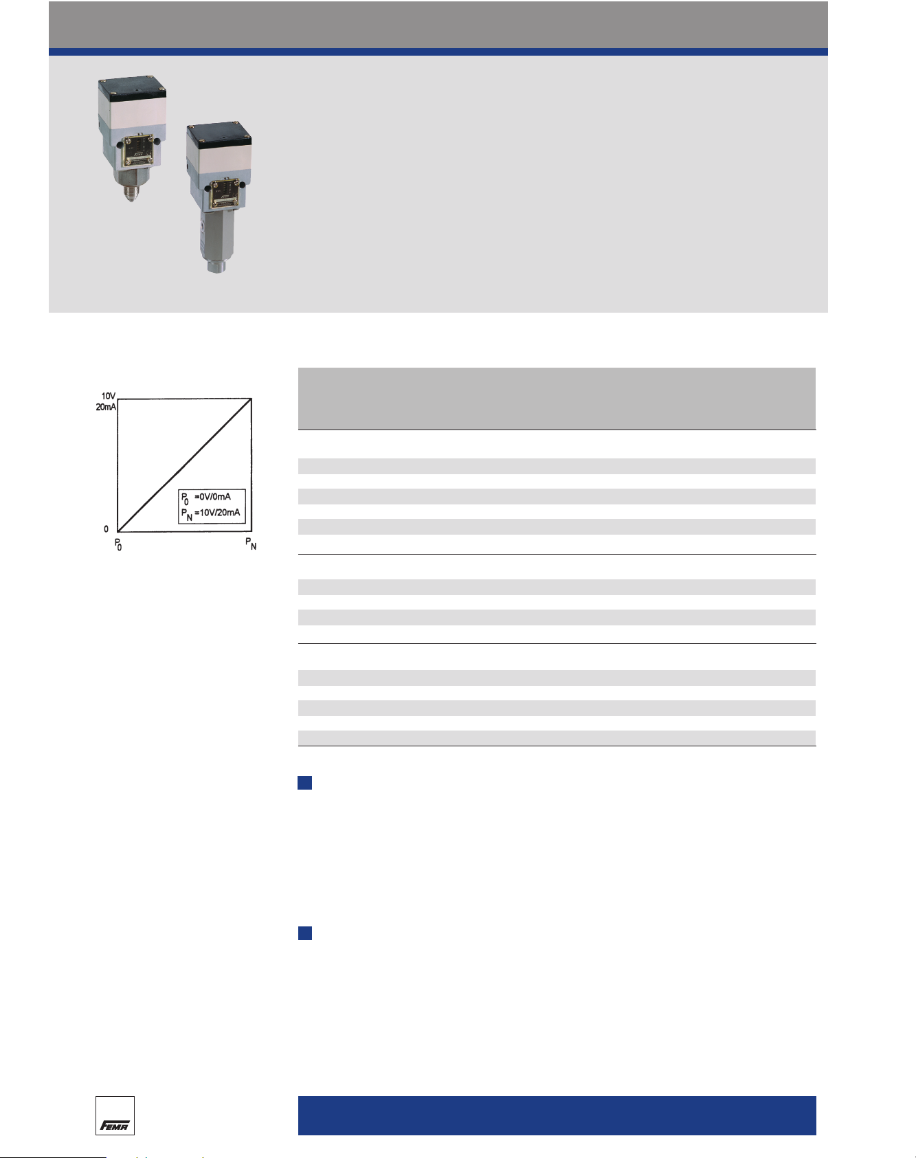
s
Characteristic of a transmitter
(nominal range)
Accessories
· Plug-in display module AZ 331
· Programmable display APV 630
For differential pressure
· Valve combination VKD 3, VKD 5
· Threaded joint with male adapter union MAU 8
Note
· If measured values diverge due to higher static (system) pressure, observe the adjustment instructions on page 71.
i
+
68
Page 3

Pressure transmitters
Type series F
Technical data
Supply voltage 24 V AC ± 20% or 24–36 V DC
Signal and supply voltage is connected to the sensor module.
Power consumption max. 1 W
Outputs (short-circuit proof) 0–10 V, 2–10 V (± 1 mA),
0–20 mA, 4–20 mA (3-conductor system)
All outputs are invertible.
Load impedance max. 750 Ohm.
Direction of action Rising pressure produces a rising output signal (default setting).
Invert with slide switch 4.
Output signal Voltage and current output can also be picked up and used
0–10 V and 0–20 mA simultaneously. Terminals 5–8 are reserved for later expansions
and must not be connected as this would destroy the device.
Operating mode mechanical, inductive
Sensor element Pressure bellows or diaphragm
Pressure connection G 1/2 external and G 1/4 internal.
On FH types: G 1/4 internal.
Cable entry 2 x M 16 x 1.5
Degree of protection IP 65
Installation Directly on the pressure line or mounted on wall with two 4 mm ø
screws.
Materials see Product Summary.
Linearity The maximum linearity error is approx. 1% of full scale.
Hysteresis approx. 0.5% nominal range, related to full output
0–10 V or 0–20 mA.
Long-term drift 0.2% FS / year
Repetition accuracy approx. 0.2%
Accuracy class 1.0
Temperature drift Range from 20–45°C approx. 0.02%/K
Range from 0–20°C approx. 0.05%/K
Influence of static pressure < = 3%/bar (see adjusting instructions, page 72)
Mounting position Vertical. With other mounting positions, the degree of protection
and accuracy are different.
Ambient temperature 0 to 45°C
Max. medium temperature 70°C. Temperatures may reach 85°C for short periods. Higher
medium temperatures are possible if the above limit values for the
switching device are ensured by suitable measures (e.g.siphon).
Storage temperature –20 to +70°C
All plugged-in modules are powered via the terminal strip of the
sensor module (on ED 1) or via the
plug connection. The output signal
is sent from each module for further evaluation via the same route.
The power consumption increases
by approx. 1 W for each additional
module plugged in.
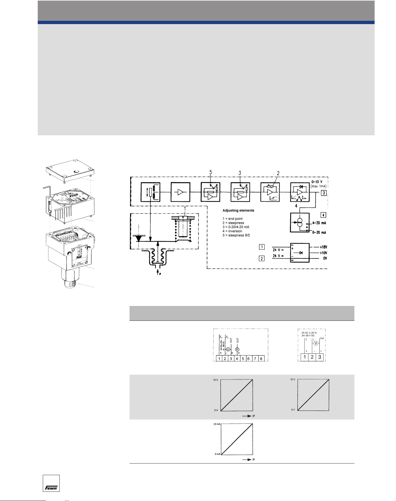
Connection schemes
Terminal connection
Plug connection
ED 3 output signal 0–10 V
Important:
When connecting to control systems
with a common AC supply, the ground
conductor must be looped through. That
is to say, on all devices in the system,
the same reference potential must be
present at the corresponding ground terminal (terminal 2). In the case of a DC
supply, ensure correct polarity.
!
70
Page 4

Type series F
Adjustment and operation
Operating ranges and output signals are adjustable
over a wide range.
An outstanding characteristic of the pressure transmitters is the variability of the characteristic curve,
which means that the pressure range and output signal can be adapted to any subsequent control
system.
P
0
= starting pressure of nominal range
P
N
= nominal pressure (end point of nominal range)
P
A
= starting pressure of set range
P
E
= end pressure of set range
Output signals for module ED 1
Basic setting
The factory default setting covers the nominal range P
0
(usually 0 bar) to PN.
Altering the range
The range can easily be altered by shifting the end point and
adjusting the steepness of the characteristic curve.
Inversion
The output signal can be inverted by means of a slideswitch.
Output signals for module ED 3
Range alteration and inversion as above.
The current signal can be reduced below 4 mA (down to approx.
2.5 mA). If the installation has a fault alarm system, the response
threshold should be set below 2.5 mA.
Pressure transmitters
Operator interface ED 1
1 = Setting spindle for setting
the final value P
E
2 = Setting potentiometer for set-
ting the initial value P
A
3 = Slide switch for selecting the
output signal 0–20 mA (0–10 V)
or 4–20 mA (2–10 V)
4 = Slide switch for inverting the
output signal
5 = Slide switch for changing the
steepness of the characteristic
in a ratio of 8:5.
Normal position: 8
For smaller operating ranges
(< approx. 70% of the nominal
range), select position 5
6 = Plug connector for further eval-
uation modules
Operator interface ED 3
1 = Setting spindle for setting
the final value P
E
2 = Setting potentiometer for set-
ting the initial value P
A
4 = Slide switch for inverting the
output signal
6 = Plug connector for further eval-
uation modules
71
Page 5

Pressure transmitters
Type series F
Setting and testing
Altering the operating range
To check functioning or change the settings from outside the system, a test set-up is required which
meets the following requirements:
1. It must be possible to apply pressure to the pressure transmitter up to the desired final value. The
pressure must be displayed by a sufficiently accurate pressure gauge.
2. To display the output signal a voltmeter with a measuring range of 0–10 V (preferably 0–15 V) or an
ammeter with a measuring range of 0–20 mA (preferably 0–25 or 0–30 mA) are required.
3. To supply power to the transmitter, a 24 V AC or 24 V DC voltage source is needed.
Setting operations must be carried out in the correct sequence
1. Remove the plastic cover
2. Set the slide switches (3) and (4) to the correct position (switch 3 is only present on ED 1)
Switch (3): Output signal 0–10 V / 0–20 mA or 4–20 mA / 2–10 V (only on ED 1)
Switch (4): Direction of action
Switch up rising pressure = rising output signal
Switch down (INV): rising pressure = falling output signal
3. Loosen the locking screw above the cover glass (approx. 2 turns anticlockwise)
4. Apply final pressure P
E
5. Using a screwdriver, turn the setting spindle (1) to the desired output signal (depending on position
of slide switches (3) and (4): 10 V, 20 mA, 0 V, 0 mA, 4 mA)
6. Apply starting pressure P
A
With the potentiometer (2), adjust the output signal to the desired value (depending on position of
slide switches: 0 V, 0 mA, 10 V, 20 mA, 4 mA)
7. Check the setting again and then retighten the locking screw for the setting spindle.
Important: Always set the upper final value P
E
with the setting spindle (1) first, and then the
lower initial value P
A
with the potentiometer (2).
Generating an output signal without pressure
It can often be very useful to generate an output signal before commissioning the system, in order to
check electrical operation, the direction of action and the functioning of downstream control elements.
The procedure is as follows:
1. Loosen the four screws on the scale window and remove the cover glass, scale plate
and rubber seal.
2. In the lower, wide part of the cut-out in the housing, insert the tip of a small screwdriver
underneath the bridge.
3. Carefully move the bridge up and down. When the supply voltage is applied, the output signal
should change depending on the movements of the bridge.
4. Check the direction of action. Upward movement of bridge corresponds to rising pressure.
5. Once you have finished testing, carefully screw the parts back on again in the following order:
rubber seal, scale plate, cover glass.
Caution: In the event of incorrect assembly, IP 65 protection is no longer assured.
Adjustment instructions: Correction of effect with static pressure
· The system in which the FHBN is installed must be filled and exposed to the usual static pressure.
· A differential pressure must not be active, i.e. no pump operation and no flow.
· Remove the plastic cover and check slide switches 3 + 4.
· The FHBN is supplied with the correct voltage and the output voltage is displayed.
· Loosen the spindle locking screw above the inspection window.
· Adjust setting spindle “1” with a screwdriver until the output signal is “0”.
· Retighten the spindle with the spindle locking screw.
72
Page 6

Type series F
Dimensioned drawings
Pressure transmitters
Dimensioned drawings
Dimensioned drawing no. Types A
1 FN 025-FN 3 55.5
FVN…
2 FHBN… 90
3 FN 505, FN 510 82
Height of evaluation module = 1 Module height = 34 mm.
The dimensions are for the basic device, consisting of sensor and
evaluation module.
Each further plug-in module increases the overall height by one
module unit = 34 mm.
1
2
3
73
 Loading...