

Page 1
User Guide
FMC2000
Page 2

FCC Information
The enclosed device complies with part 15 of the FCC rules.
Operation is subject to the following conditions: (1) This device
may not cause harmful interference, and (2) This device must
accept any interference received, including interference that
may cause undesired operation.
Proper Product Disposal At End Of Life
This symbol (crossed-out wheeled bin) indicates
separate collection of waste electrical and electronic
equipment in the EU countries.
This product may contain one or m ore lead-acid, Nickelmetal hydride (NiMH), Lithium-ion, or Alkaline
batteries. Specific battery information is given in this
user guide.
Batteries must be recycled or disposed of properly.
At the end of its life, this product must undergo separate collection
and recycling from general or household waste. Please use the return
and collection system available in your country for the disposal of this
product.
© Copyright 2014 Honeywell Analytics
Page 3

FMC2000 User’s Guide
Contents
1 Special Notes .................................................................. 6
Warnings ......................................................................... 7
2 Standard Contents ........................................................... 8
3 General Informat io n ....................................................... 8
3.1 Key Features ............................................................... 8
4 Physical Description ....................................................... 9
4.1 Rear View and Side View Of Enclosure .................. 10
4.2 Mounting the FMC2000 ........................................... 10
4.3 Drilling Chart ............................................................ 12
5 Specifications ............................................................... 13
6 Charging The Internal Backup Battery ......................... 14
6.1 Clock Battery ............................................................ 14
6.2 Data Protection While Power Is Off ......................... 14
6.3 SD Card .................................................................... 14
7 User Interface ............................................................... 16
7.1 Status LEDs .............................................................. 17
7.2 Display ...................................................................... 17
7.3 Keypad ...................................................................... 18
7.4 Alarms ...................................................................... 18
7.5 Preparing The FMC2000 For Data Storage ................. 19
8 Operating The FMC2000 ............................................. 22
8.1 Turning The FMC2000 On ....................................... 22
8.2 Turning The FMC2000 Off ...................................... 24
9 Display Information ...................................................... 25
9.1 Display Icons ............................................................ 26
10 Navigation .................................................................... 28
11 Normal Operation Mode Controls ................................ 29
11.1 Radio Silent (Enable/Disable) .................................. 29
11.2 Reset ......................................................................... 29
11.3 Silence Alarm ........................................................... 30
11.4 Check (Alarm Details) .............................................. 31
11.5 Monitoring ................................................................ 33
11.5.1 Detail Info .............................................................. 33
11.5.2 MeshGuard EC Or LEL ......................................... 34
1
Page 4

FMC2000 User’s Guide
11.5.3 MeshGuard Router ................................................ 36
12 Configuration ................................................................ 37
13 General Settings Menu ................................................. 38
13.1 Basic Settings ........................................................... 39
13.2 Date Format .............................................................. 40
13.3 Date ........................................................................... 40
13.4 Time Format ............................................................. 41
13.5 Time .......................................................................... 41
13.6 Language .................................................................. 43
13.7 Backlight ................................................................... 43
13.8 Instrument Location .................................................. 44
13.9 Serial Number ........................................................... 44
13.10 Firmware Version ................................................. 44
13.11 Build Date ............................................................. 44
13.12 Build Time ............................................................ 44
14 Advanced Settings ........................................................ 45
14.1 Basic Password ......................................................... 45
14.2 Advanced Password .................................................. 46
14.3 Online Monitors ........................................................ 46
14.4 Delete Monitors Configuration ................................. 47
14.5 Delete Relay Configuration ...................................... 47
14.6 EchoView ................................................................. 47
14.7 Alarm Buzzer ............................................................ 47
14.8 Alarm Light .............................................................. 48
14.9 Backup Configuration .............................................. 48
14.10 Restore Configuration .......................................... 48
14.11 Factory Reset ........................................................ 49
15 Wireless Detector Settings ........................................... 49
15.1 Modem ID ................................................................ 50
15.2 Location .................................................................... 50
15.3 Data Interval ............................................................. 50
15.4 Sensor Type .............................................................. 51
15.5 Unit ........................................................................... 51
15.6 Low ........................................................................... 51
15.7 High .......................................................................... 51
15.8 STEL ......................................................................... 51
2
Page 5

FMC2000 User’s Guide
15.9 TWA ......................................................................... 52
15.10 Full Scale .............................................................. 52
15.11 Drift ...................................................................... 52
15.12 Reset LEL ............................................................. 52
16 Relay Settings ............................................................... 53
16.1 Relay Ratings (Resistive) ......................................... 53
16.2 Type .......................................................................... 54
16.3 DON ......................................................................... 54
16.4 DOF .......................................................................... 55
16.5 Lock .......................................................................... 55
16.6 Vote .......................................................................... 56
16.7 Num .......................................................................... 57
16.8 Slave ID .................................................................... 57
17 Datalog Settings Menu ................................................. 58
17.1 Datalog ..................................................................... 58
17.2 Log Interval .............................................................. 59
17.3 Log Method .............................................................. 59
17.4 SD Card Info ............................................................. 60
18 Communications Menu ................................................ 61
18.1 Wireless Modem ....................................................... 62
18.1.1 Form a Network ..................................................... 62
18.1.2 Radio Synch ........................................................... 62
18.1.3 Radio PanID .......................................................... 63
18.1.4 Del Binding ........................................................... 64
18.1.5 Channel .................................................................. 64
18.1.6 Ping Network ......................................................... 64
18.2 Ethernet Network ...................................................... 65
18.2.1 TCPIP Enable ........................................................ 65
18.2.2 Protocol Select ....................................................... 66
18.2.3 Server IP ................................................................ 67
18.2.4 Server Port ............................................................. 67
18.2.5 Client IP ................................................................. 67
18.2.6 Subnet Mask .......................................................... 68
18.2.7 Dflt Gateway ......................................................... 68
18.2.8 Re-Obtain IP .......................................................... 69
18.2.9 Client MAC ........................................................... 69
3
Page 6

FMC2000 User’s Guide
18.3 RS485 ....................................................................... 70
18.3.1 Baud Rate .............................................................. 70
18.3.2 Client ID ................................................................ 71
18.3.3 MB Type ................................................................ 71
18.3.4 Protocol .................................................................. 72
18.3.5 Monitor Address .................................................... 72
19 Diagnostic Menu .......................................................... 73
19.1 Relay Output Diagnostic .......................................... 73
20 Transferring Data From The SD Card .......................... 75
21 After Transferring Data From The SD Card ................ 77
22 Maintenance ................................................................. 79
22.1 Battery Charging & Replacement ............................ 79
22.2 SD Card Replacement .............................................. 79
22.3 Special Servicing Note ............................................. 80
23 Troubleshooting ............................................................ 81
24 Technical Support ......................................................... 83
25 Honeywell Analytics Contacts ..................................... 84
26 Appendix A: Wiring The FMC2000 ............................ 86
26.1 DC Wiring ................................................................ 86
26.2 AC wiring ................................................................. 86
27 Appendix B: Wiring To External Alarms .................... 91
27.1 Wiring Blocks In The FMC2000 ...................................... 88
27.2 Relay Electrical Drawing ......................................... 89
27.3 Checking Relay Continuity ...................................... 90
27.3.1 Power Supply Connections .................................... 91
27.3.2 Dry Contact Operation .......................................... 92
28 Appendix C: Connecting RS485 (Modbus) ................. 92
29 Appendix D: Connecting Ethernet ............................... 93
30 Appendix E: Connecting to a Light/Alarm Bar ............ 94
31 Appendix F: Formatting An SD Card For FAT32 ....... 95
31.1 Formatting An SD card ............................................ 95
32 Appendix G: ModBus Protocol For The FMC2000 ... 101
32.1 Overview ................................................................ 101
32.2 Communications Settings ....................................... 101
32.3 Message Frame/Communication Procedure ........... 102
32.4 Registers Table ....................................................... 103
4
Page 7

FMC2000 User’s Guide
Read Before Operating
This manual must be carefully read by all individuals who have or
will have the responsibility of using, maintaining, or servicing this
product. The product will perform as designed only if it is used,
maintained, and serviced in accordance with the manufacturer’s
instructions. The user should understand how to set the correct
parameters and interpret the obtained results.
CAUTION!
To reduce the risk of electric shock, turn the power off before
opening this instrument or performing service. Never operate the
instrument when the instrument is open. Use and service this
product only in an area known to be non-hazardous.
5
Page 8
FMC2000 User’s Guide
1 Special Notes
If the battery backup is completely discharged, the power
switch must be turned off and on when the main power is
restored.
An SD card is required for storing datalog information. If the
card is not factory formatted for FAT32, it must be formatted
before use. See Appendix C.
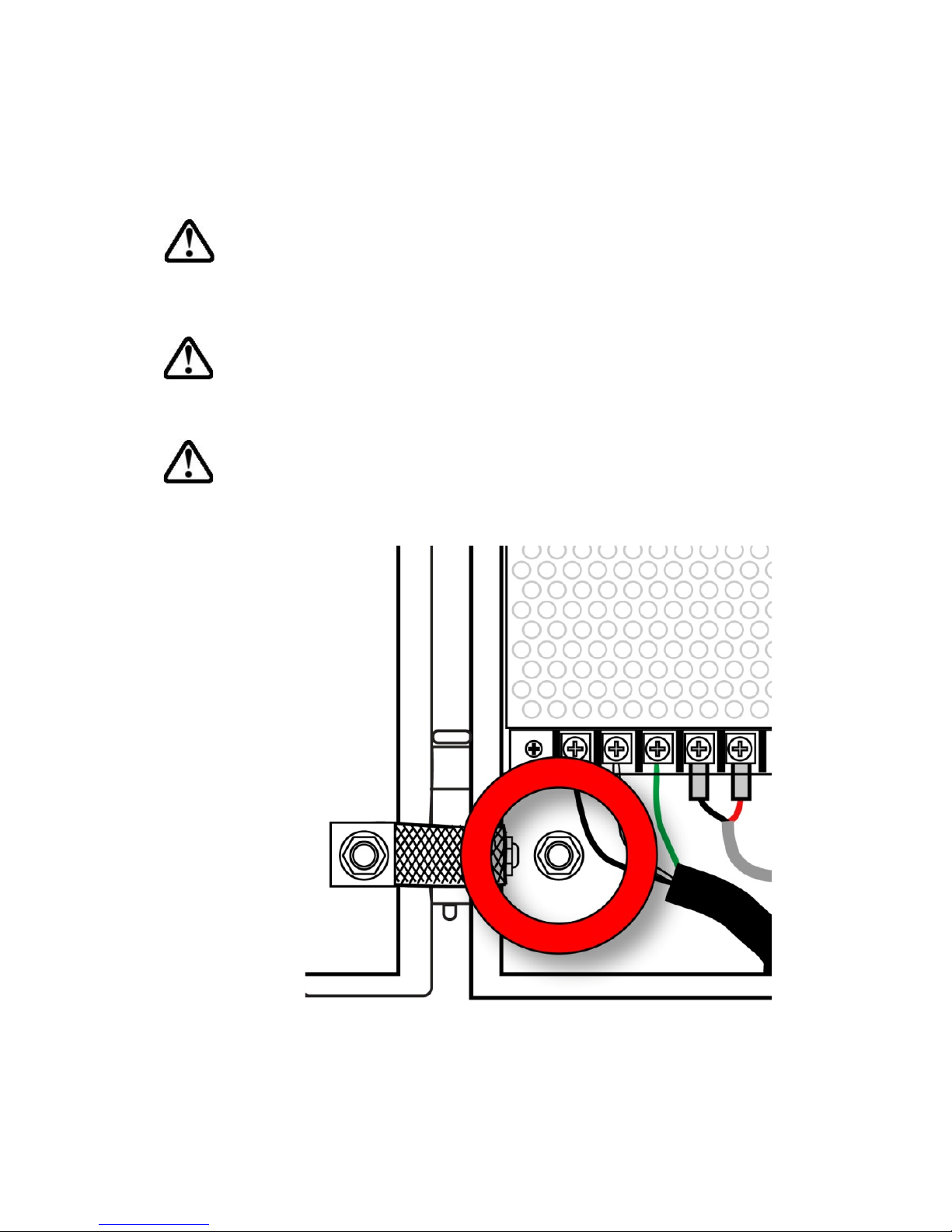
The FMC2000 must be properly grounded. Follow local
electrical codes when installing and using. Connect a ground
wire to the bolt inside the front panel to ground the chassis:
6
Page 9

FMC2000 User’s Guide
WARNINGS
Use only in non-hazardous locations.
For safety reasons, this equipment must be operated and serviced
by qualified personnel only. Read and understand instruction
manual completely before operating or servicing.
AVERTISSEMENT
Utiliser uniquement en zone non-dangereuse.
Pour des raisons de sécurité, cet équipment doit être utilisé,
entretenu et réparé uniquement par un personnel qualifié. Étudier
le manuel d’instructions en entier avant d’utiliser, d’entretenir ou
de réparer l’équipement.
7
Page 10

FMC2000 User’s Guide
2 Standard Contents
• Controller mounting plate (as specified)
• Key for cabinet lock
• SD memory card
• Installation guide/quick-start guide
• CD-ROM with User’s Guide, Quick-Start Guide, and
related materials
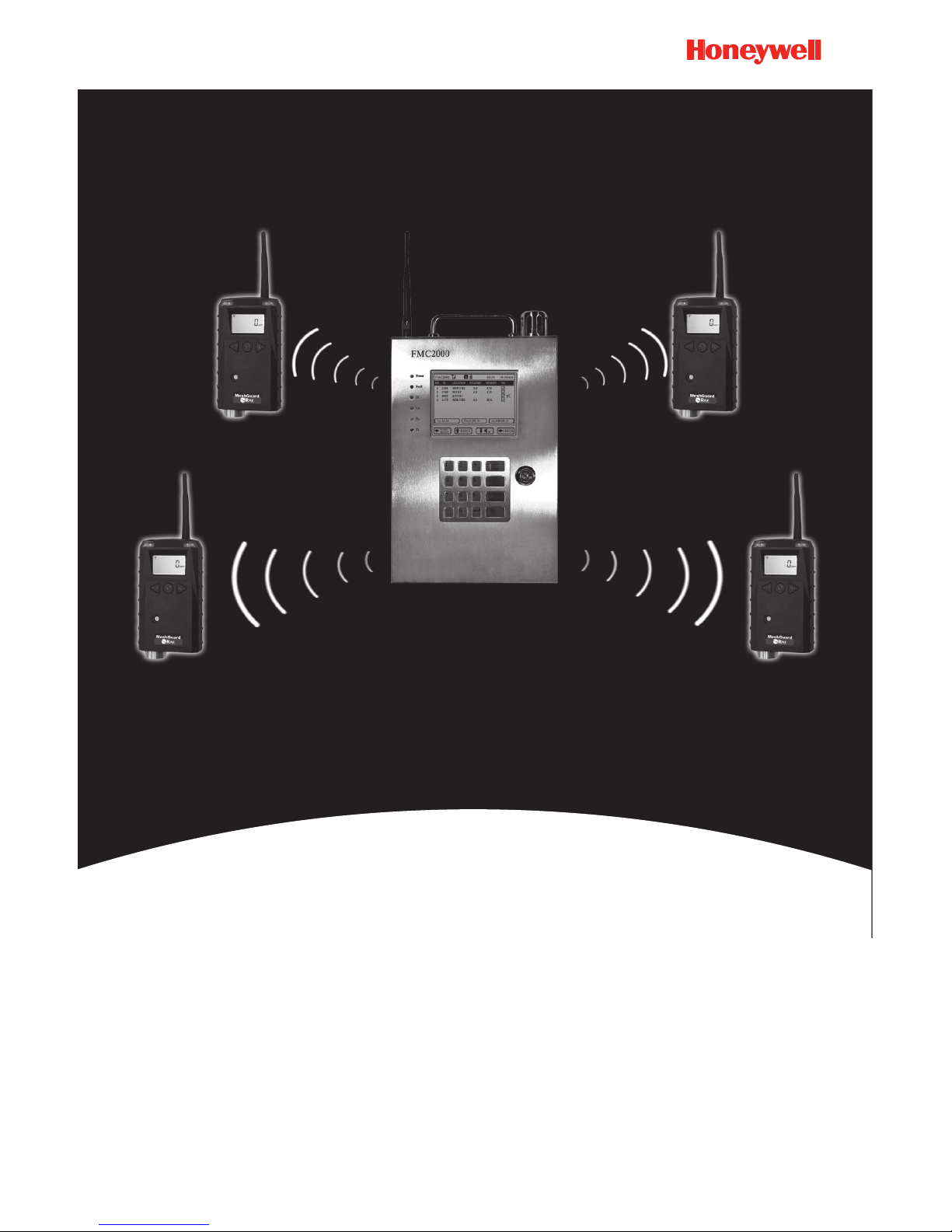
3 General Information
The FMC2000 Multi Controller works with provided by
Honeywell Analytics Mesh wireless detectors, such as
MeshGuard, RAETag, RAEWATCH, for various safety
applications.
3.1 Key Features
• Rapid deployment.
• Wireless mesh network communication.
• 5.7″ high-contrast graphic LCD display. Good for outdoor
applications.
• Integrated visual indicator and audio alarm.
• 5 SPDT relays for alarms and fault.
• Datalogging storage on SD card.
• Configuration storage/retrieval on SD card.
• Can manage up to 24 wireless monitors.
• User programmable.
• Wide power input range: 100V to 240VAC
8
Page 11
FMC2000 User’s Guide
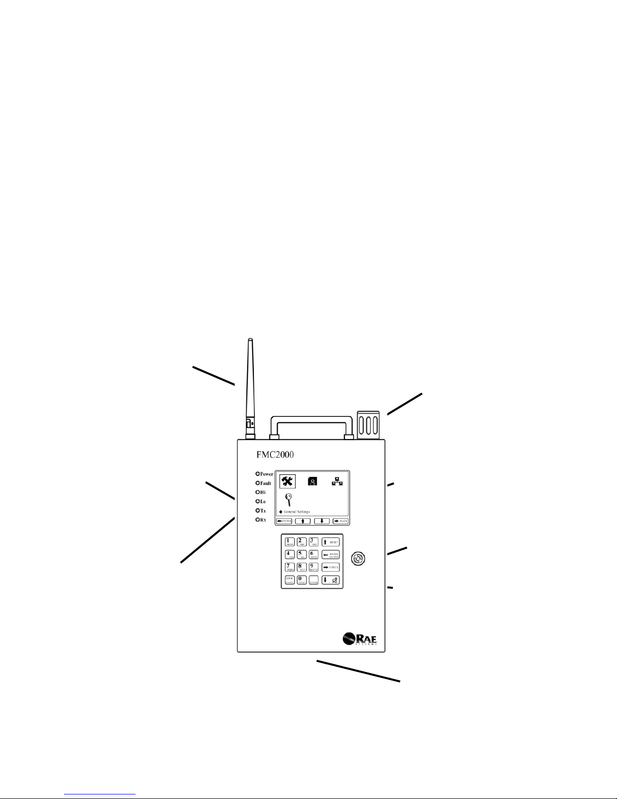
4 Physical Description
The main components of theFMC2000 include:
• 16 keys for programming and reviewing settings
• LCD display with back light for direct readout and readout
from MeshGuard monitors
• Buzzer and red light for alarm signaling whenever exposures
exceed preset limits
• Key-lockable panel
• Stainless-steel housing
Antenna
Handle
Alarm Light
Status LEDs
Keypad
Display
Alarm
Buzzer
(on side)
Lock
Wire
Pass-Throughs
(on bottom)
9
Page 12
FMC2000 User’s Guide
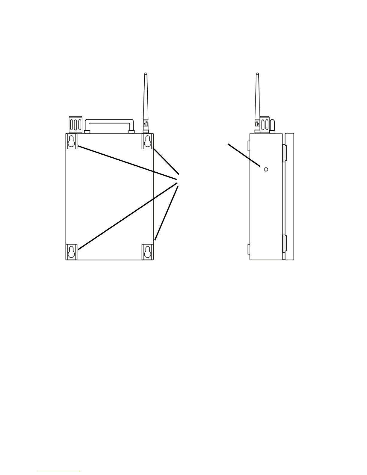
4.1 Rear View and Side V iew Of Enclosure
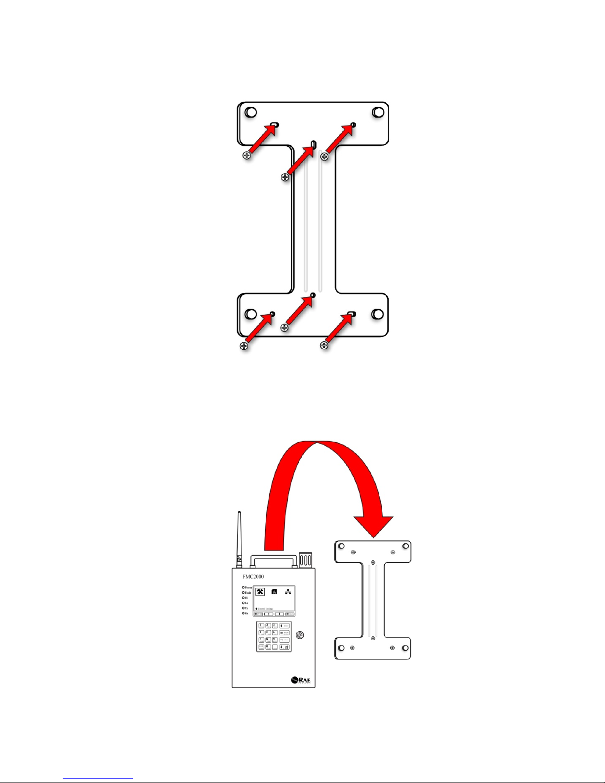
4.2 Mounting the FMC2000
The FMC2000 is designed to be wall-mounted and has four
keyhole-type captures on its back, allowing for attachment to four
mating studs extending from a bracket that is designed to be preinstalled on a wall.
Follow these steps:
1. Install the mounting plate first. Mark the locations for the six
screws.
Alarm
Buzzer
Mounting
Captures
10
Page 13
FMC2000 User’s Guide
2. Drill the holes and screw the bracket to the wall.
3. Support the weight of the FMC2000 and align the large ends
of the keyhole-shaped mounting captures on the rear of the
enclosure with the four studs protruding from the bracket.
11
Page 14

FMC2000 User’s Guide
4. Ensure the shafts of the mounting plate’s studs rest firmly in
the narrow end of the keyhole-shaped captures, and then let
the bracket fully bear the weight of the FMC2000.
4.3 Drilling Chart
When mounting the FMC2000 on a wall, make sure to use heavy-
duty steel screws spaced as indicated below.
Note: All dimensions are in mil limeters.
12
Page 15

FMC2000 User’s Guide
5 Specifications
Size
9.5" W x 15.7" H x 3.7" D
(24cm x 40cm x 9.3cm)
Weight
14.3 lbs (6.5 kg), excluding mounting plate
LCD Display
5.7″ (15cm) 320x240 Black/White graphic
LCD with backlight
Audible alarm
95dB @ 30cm (12″)
Visual alarm
Super-bright red LED with enclosed cover
Keypad
16 metal keys
Real-Time Clock
YY/MM/DD,HH:MM:SS
Datalogging
SD card
Wireless
2.4GHz IEEE 802.15.4/ mesh radio
Wireless
Detectors
24 channels
Relays
Resistive Load Max: 6A@24VDC or
6A@250VAC
Limiting making current Max: 10A
Breaking switching power capacity Max:
1200VA
Housing
Stainless steel
Power Supply*
100V to 240V AC
Backup Battery
Rechargeable lead-acid battery
12V 2.8AH, 15 hours of operation
Operating
Temperature
-20° C to +55° C
Approvals
FCC: SU3RM2400A
EC Compliance
(European
Conformity)
EMC Directive : 2004/108/EC
R&TTE Directive : 1999/5/EC
LVD Directive : 2006/95/EC
Humidity
0% to 95% RH, non-condensing
*Power source must be protected by a circuit breaker or fuse rated
at 15A or less.
13
Page 16

FMC2000 User’s Guide
Radio Specific a ti ons
Radio model: RM2400A
Frequency range: 2.400-2.4835GHz
Modulation: 802.15.4 DSSS BPSK
RF power(Tx): 20dBm
Data rate: 250kbps
6 Charging The Internal Backup Battery
Whenever AC power is supplied to the FMC2000, the internal
backup battery is always being charged. The backup battery
ensures continuous operation if the AC power source is
interrupted. It is fully charged after 6 to 8 hours of operation.
The FMC2000 can run for up to 15 hours on the backup battery.
6.1 Clock Battery
An internal clock battery is mounted on the top printed circuit
board. This long-life battery keeps settings in memory from being
lost whenever the power is turned off or disconnected. This clock
battery should last approximately five years, and must be replaced
by an authorized Honeywell Analytics service technician. It is not
user-replaceable.
6.2 Data Protection While Power Is Off
When the FMC2000 is turned off, all the current real-time data
including last measured values are erased. However, the datalog
data is preserved on an SD card if it is installed. Even if the
battery is disconnected, the datalog data will not be lost.
6.3 SD Card
The FMC2000 uses an SD (Secure Digital) card for datalog
storage.
14
Page 17

FMC2000 User’s Guide
WARNING!
Whenever you replace the SD card, the FMC2000 must be either
turned off or in standby mode (see page 19). Otherwise, data may
be lost or the SD card may be corrupted. See “Preparing The
FMC2000 For Data Storage” on page 19 for details on safely
inserting and removing an SD card.
IMPORTANT!
The SD card that comes with the FMC2000 is pre-formatted and
ready for use. If you purchase an SD card from another vendor, its
capacity must be 2GB or less. In addition, it may need to be
formatted before it can be used in the FMC2000. Honeywell
Analytics cannot guarantee SD cards from other sources will work
with the FMC2000. Refer to Formatting An SD Card on page 94
for details.
Note: The SD card inside the FMC2000 should only be used for
FMC2000 data recording. Do not save other files to the SD card.
In addition, do not use one SD card for more than one FMC2000
or exchange it from one FMC2000 to another.
Transferring records from the SD card to a PC every 6 month is
recommended. This enhances data security and speeds the datatransfer process.
15
Page 18
FMC2000 User’s Guide
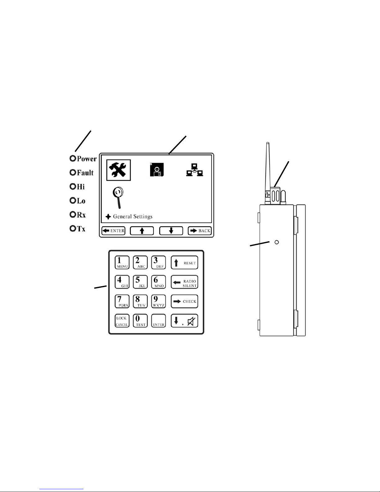
7 User Interface
The instrument’s user interface consists of the display, status
LEDs, an alarm buzzer, an alarm light, and 16 keys.
Alarm
Buzzer
Alarm
Light
Status
LEDs
Display
Keypad
16
Page 19
FMC2000 User’s Guide
7.1 Status LEDs
The status LEDs provide the following basic visual information:
LED
Information
Power
Glows green when the FMC2000 is on
Fault
Glows orange when problem is encountered
Hi
Glows red during High Alarm
Lo
Glows red during Low Alarm
Rx
Glows green when receiving data from a remote
device
Tx
Glows green when transmitting data to a remote
device
7.2 Display
The LCD display provides visual feedback that includes the
reading, time, battery condition, and other functions. It also
includes “soft key” indicators along the bottom that show the
relationship of functions with the large buttons arranged vertically
along the keypad’s right side.
17
Page 20
FMC2000 User’s Guide
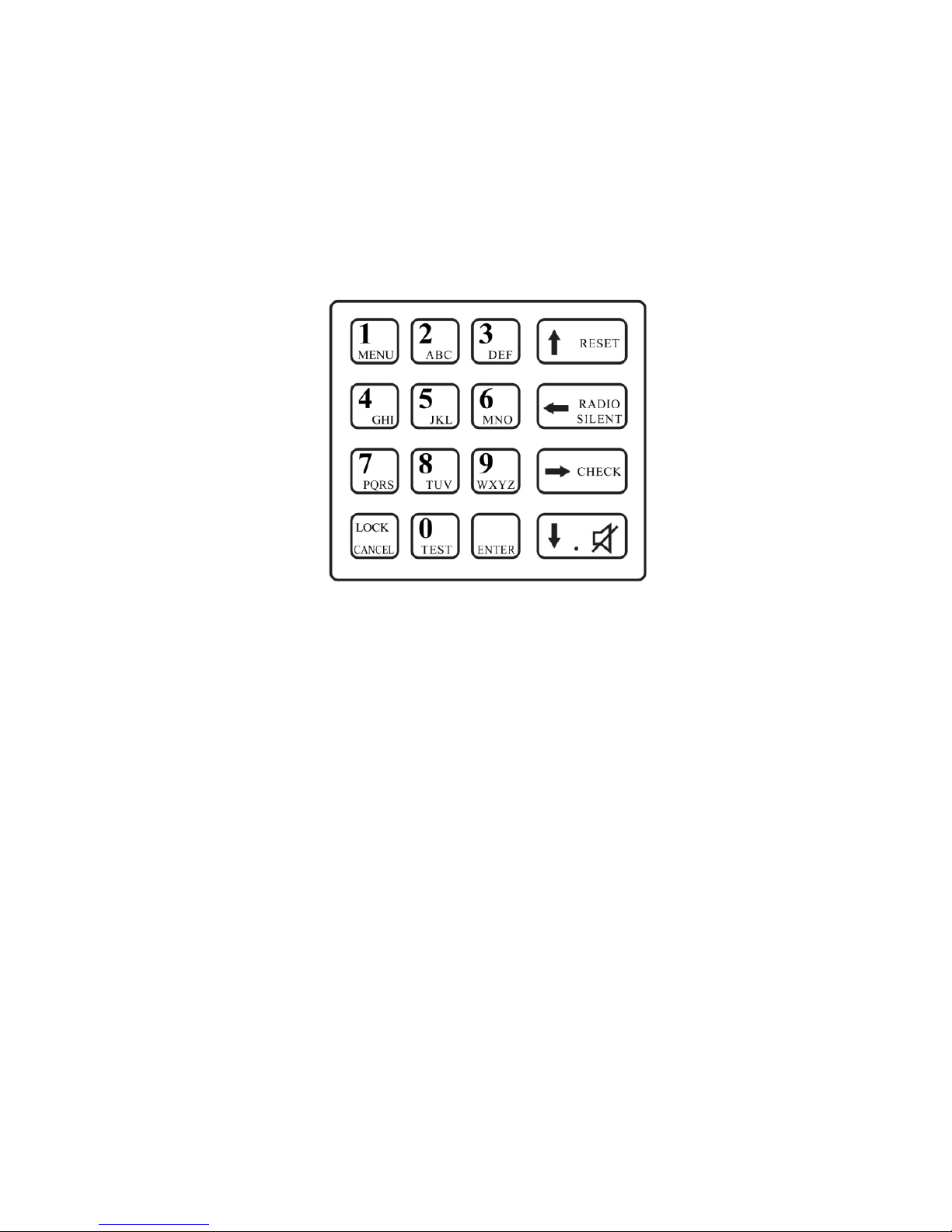
7.3 Keypad
The keypad is used to navigate the menus and parameters in the
FMC2000. Many of the keys perform dual functions, and the four
large keys arranged vertically along the right side correspond to
the “soft key” icons arranged along the bottom of the display.
7.4 Alarms
Three types of alarms can occur:
• Fault
• Low alarm
• High alarm
A fault alarm occurs when there is a low battery in a monitor
transmitting to the FMC2000, when a monitor goes “offline” or
out of range (and its signal is no longer received), or when there is
an internal problem with the FMC2000. Low and high alarms
occur when any of the network’s monitors’ thresholds are
exceeded.
Note: If a low alarm is triggered and then a high alarm, the low
alarm continues to occur until all alarms are cleared.
18
Page 21
FMC2000 User’s Guide
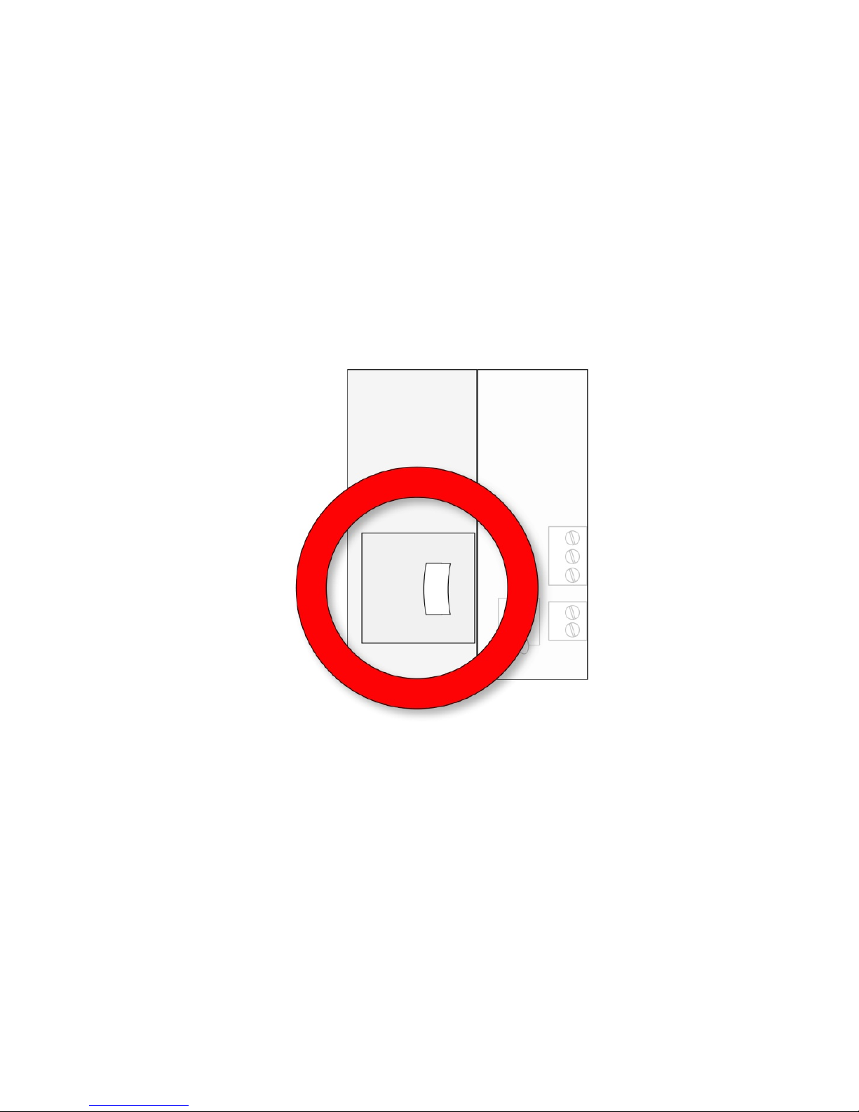
7.5 Preparing The FMC2000 For Data Storage
Before operating the FMC2000, make sure it has an SD card in the
memory slot. This is necessary for storing datalog information.
1. Unlock the FMC2000.
2. Open the door.
The SD card slot is on the main PC board as shown:
IMPORTANT!
Before inserting or removing an SD card, the FMC2000 must be
turned off, datalogging turned off, or the FMC2000 placed in
Standby Mode. For details on turning datalogging off, see page
58. For details on turning the FMC2000 off or on, see page 22.
19
Page 22
FMC2000 User’s Guide
To place the FMC2000 in Standby Mode and replace the SD
card:
1. Hold down the “2” key until you see the display message
“Standby...” The screen goes blank.
2. Release the “2” key.
3. Unlock and open the front panel.
4. Check that LED next to the SD card is not blinking.
5. Remove SD Card by pressing in (lightly), and allowing it to
release.
6. Replace the SD card.
To exit Standby Mode and restart datalogging:
1. Hold down the “2” key. The screen illuminates and gives the
message “Working...”
2. Release the “2” key.
When the reading display is shown, datalogging is on again, and
the FMC2000 is fully operational.
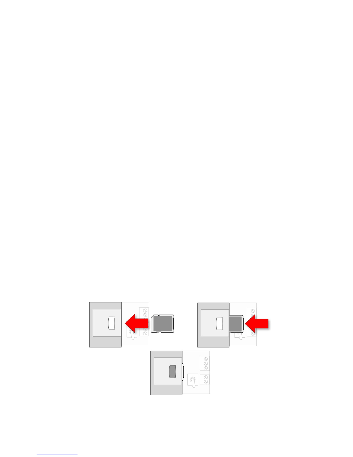
Inserting an SD card. Press the SD card into the slot with the
angled notch on the right. Press until it locks into place, making a
“click” sound.
20
Page 23
FMC2000 User’s Guide
Removing an SD card. Press the SD card and release it. It will
make a click and push part of the way out of the slot.
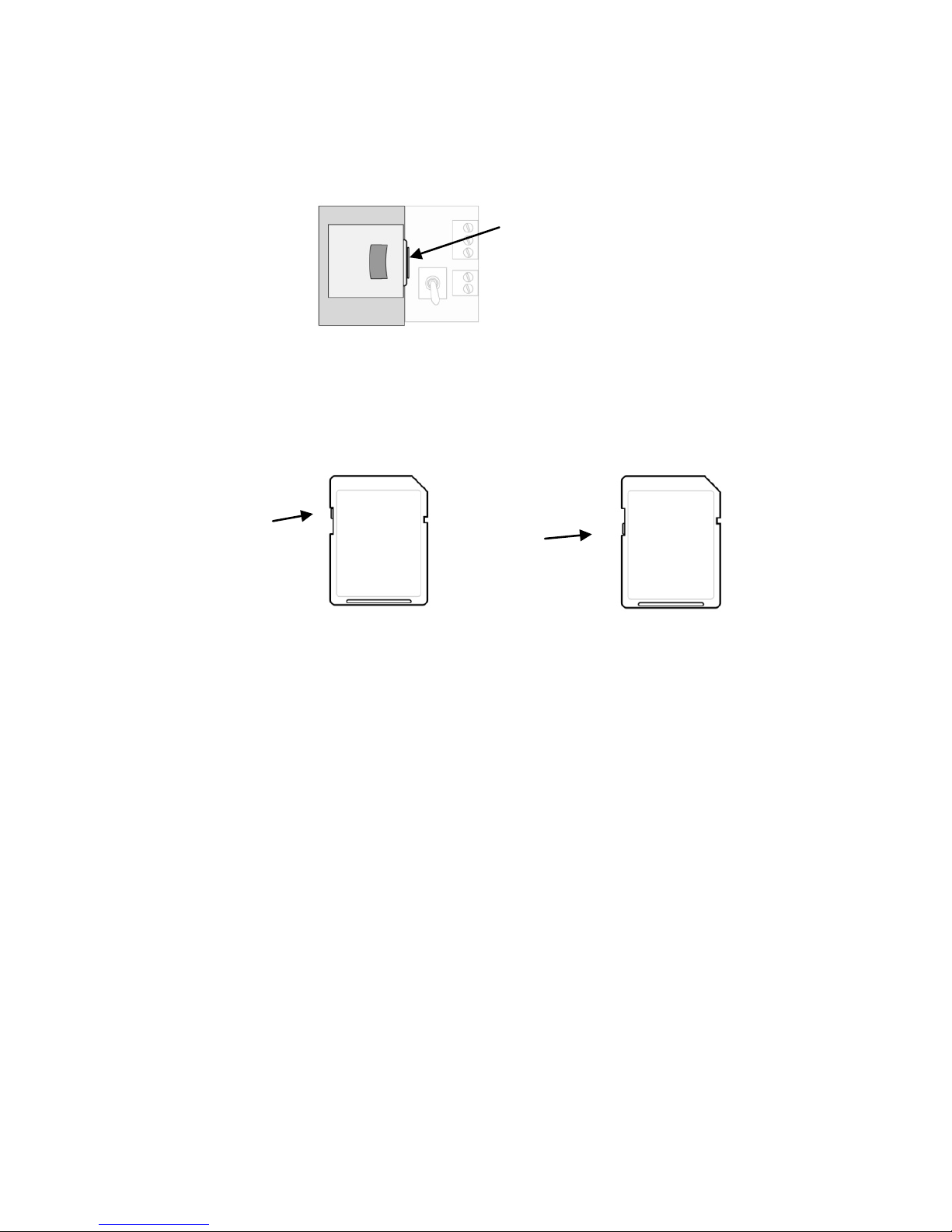
The FMC2000 cannot write data to a locked SD card. If the SD
card is locked, remove it and unlock it by moving the lock tab;
then reinsert the SD card.
Unlocked SD Card
Locked SD Card
If remaining space for data on the SD card is very low, the
FMC2000 alerts you with a message on the screen. Replace the
SD card with another with more space on it, or offload the data to
a computer. Then erase the data from the card, using your
computer, and reinsert the SD card back into the FMC2000.
IMPORTANT!
Keep enclosure closed whenever an SD card is not being inserted
or removed. This helps to keep the reading mechanism and the SD
card clean, especially in dusty environments.
Lock
Tab
Lock
Tab
Press here
21
Page 24
FMC2000 User’s Guide
8 Operating The FMC2000
The FMC2000 starts up quickly and requires no intervention on
the part of the user, other than turning on the power switch. Once
it is powered up, the FMC2000 performs self-tests and
automatically initiates communications.
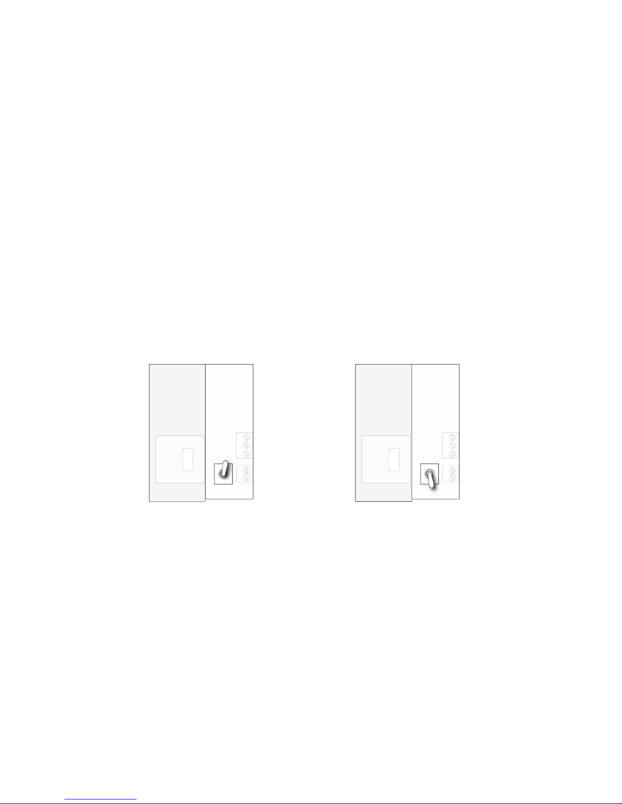
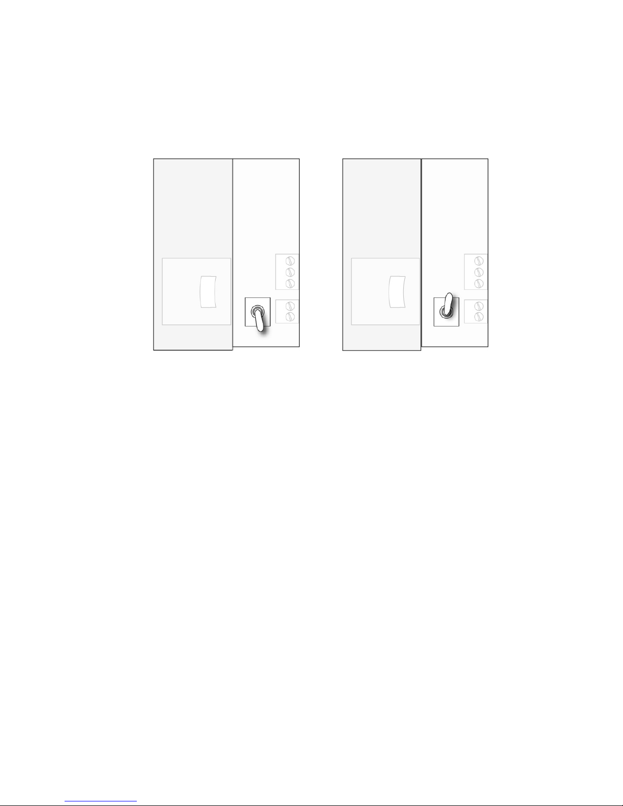
8.1 Turning The FMC2000 On
1. Connect the FMC2000 to a source of AC power.
2. With the FMC2000 turned off, unlock the front panel with the
key, and flip the small toggle switch located next to the SD
card.
LEDs inside the FMC2000 indicate proper operation:
• If the radio transmitter is on, the LED next to it should
blink.
• If datalogging is turned on, the LED next to the SD card
should blink.
3. Close and lock the front panel.
Switch in “on” position
Switch in “off” position
22
Page 25
FMC2000 User’s Guide
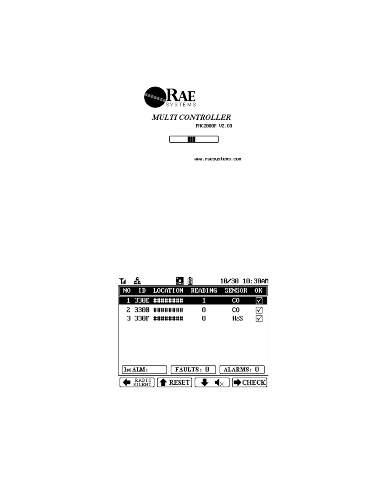
A screen with the RAE Systems logo appears first. (If the logo
does not appear, there is likely a problem and you should contact
Honeywell Analytics Technical Service.
\
The FMC2000 performs self-tests on its LCD, LEDs, and buzzer.
It also initializes connection with a wireless network or Ethernet
interconnection (if it is configured for Ethernet networking). After
30 seconds, the display shows the monitoring screen, indicating
that it is monitoring the system. It is now fully operational. If any
tests fail, refer to the Troubleshooting section of this guide.
Once the startup procedure is complete, the instrument shows
readings from any MeshGuard sensors on the network:
Note: Always start the FMC2000 controller first, before starting
MeshGuard monitors.
23
Page 26
FMC2000 User’s Guide
8.2 Turning The FMC2000 Off
1. Unlock the case.
2. Flip the switch located next to the SD card.
3. Check that the LEDs are no longer glowing. This indicates the
FMC2000 is off.
Note: After starting or shutting down the FMC2000, we
recommend locking the case again to keep dust out, and to prevent
tampering by unauthorized personnel.
Note: The power supply has no user-serviceable parts.
Switch in “off” position
Switch in “on” position
24
Page 27
FMC2000 User’s Guide
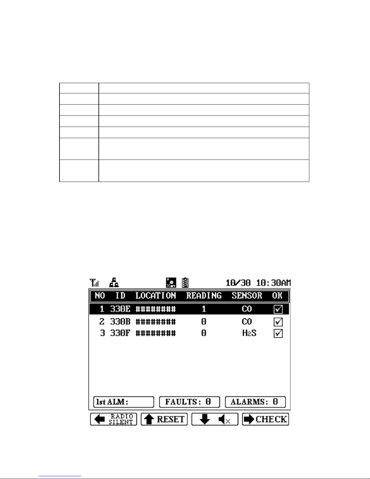
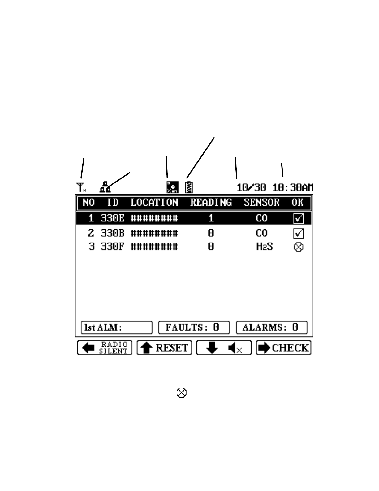
9 Display Information
If remote monitors are connected and sending data to the
Controller, each monitor’s data is shown in a row with an
identification number, radio ID, Station name, sensor value
(reading), sensor type, and status (OK checked).
Note: When wireless connectivity to an instrument is lost, the
checkbox under the “OK” heading is replaced by this symbol:
The instrument is not removed from the list. Instead, it drops to
the bottom of the list. If connectivity is restored, the checkbox is
shown again.
Time
Power Type
Date
Datalogging
Status
Wireless
Status
Network
Status
25
Page 28
FMC2000 User’s Guide
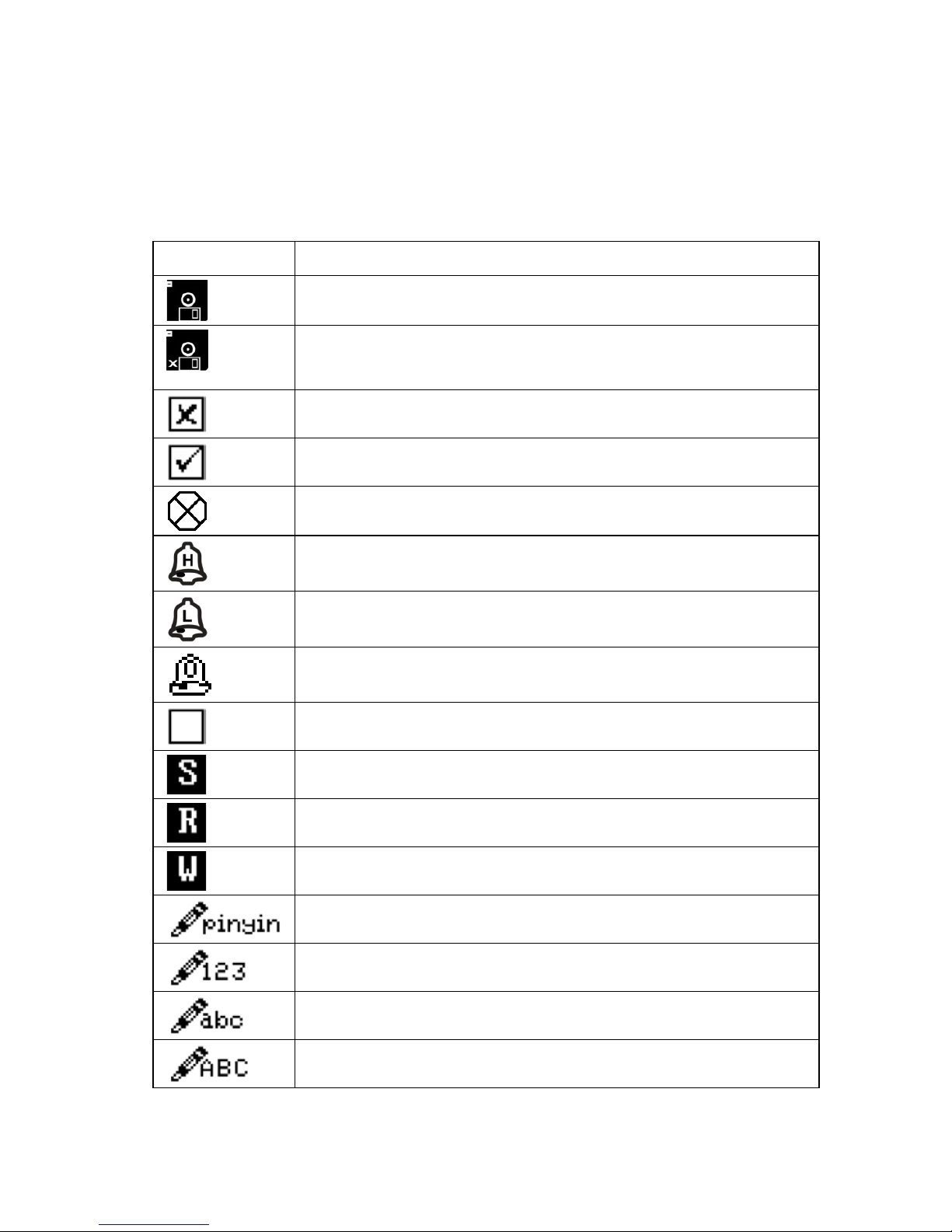
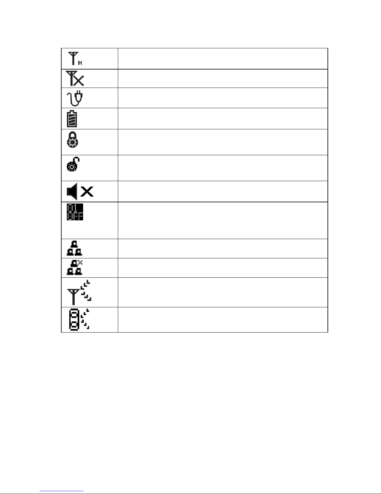
9.1 Displa y Icons
Icons show active functions and alert you to conditions. The icons
used by the FMC2000 include:
Icon
Function
Datalogging is active
(Flashing icon) SD card is missing; datalogging
stopped
Detector sensor error
Detector sensor okay
Monitor offline
High alarm
Low alarm
Over-range alarm
Check box
Select from a list
Read-only information (cannot be changed)
Writable parameter
Prompt for inputting simplified Chinese characters
Prompt for inputting numerical data
Prompt for inputting lower-case letters
Prompt for inputting upper-case letters
26
Page 29
FMC2000 User’s Guide
Radio enabled (Host)
Radio disabled
FMC2000 is running on AC power
FMC2000 is running on battery power
Locks to the selected sensor before checking details
(stops automatic updating)
Unlocks the selected sensor (resumes automatic
updating)
FMC2000 alarm is silenced
Monitor missing (shows the number of monitors
missing from the network, such as “01 OFF,” “02
OFF,” etc.)
Data connection via Ethernet is operational.
Data connection via Ethernet is not operational.
Indicates MeshGuard Router
Indicates RAEPoint wireless relay
27
Page 30
FMC2000 User’s Guide
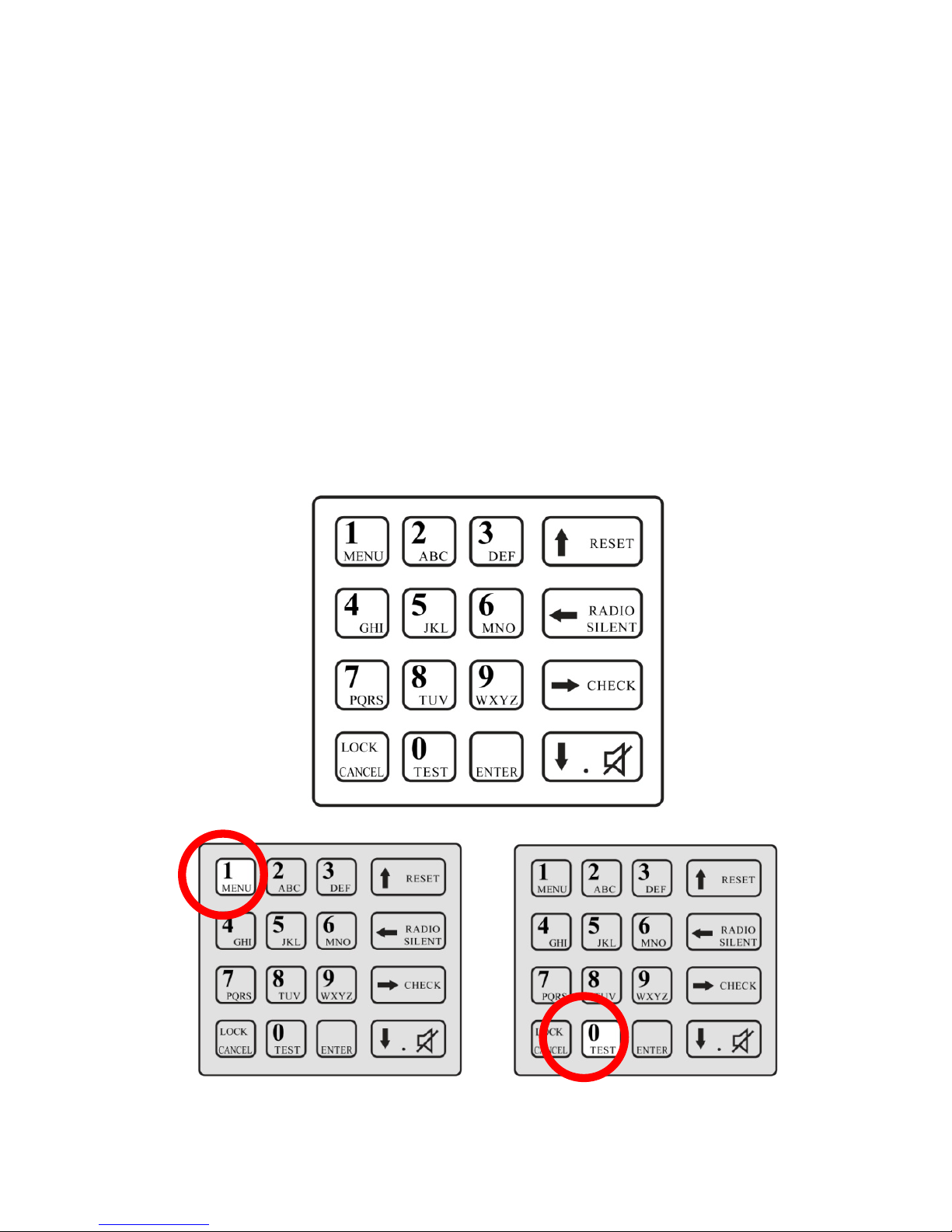
10 Navigation
The four “soft-key” buttons shown along the bottom of each
screen on the display indicate which buttons to press on the
keypad to perform specific functions, including navigation and
changing parameters.
In addition to labeled functions, most keys have more than one
role. For example, pressing the “1” key while the FMC2000 is
monitoring enters the main menus, while pressing the “0” key tells
it to perform a system test (this requires a 4-digit password; the
default is 1234).
28
Page 31

FMC2000 User’s Guide
11 Normal Operation Mode Controls
From the normal operation screen, you can use the “soft keys” to
do the following:
• Radio Silent. Turn the radio on or off (enable/disable).
• Reset. Reset the system.
• Alarm Silent. Silence the alarm.
• Check. Get alarm details.
11.1 Radio Silent (Enable/Disable)
The radio can be turned off so that it cannot transmit or receive.
1. Press the Radio Silent/left arrow button.
A warning screen is shown.
2. Enter the 4-digit password (the default is 1234).
3. Press Enter.
The icon changes from the enabled state to the disabled state (see
Display Icons, page 26), and the screen button says “Radio
Enable” instead of “Radio Silent.” To change the state from
disabled back to enabled, follow the same procedure.
11.2 Reset
This resets (reboots) the system.
1. Press the Reset/up-arrow button.
2. Enter the 4-digit password (the default is 1234).
3. Press Enter.
The system is now reset
29
Page 32

FMC2000 User’s Guide
11.3 Silence Alarm
If the system is in alarm, you can silence the local alarm buzzer.
Press the down-arrow/alarm-silence button. The local alarm
buzzer is silenced, but the red alarm light continues to flash and
the relay continues to act in the state of alarm. If the relay setting
is set to latch, a pop-up screen asks if you want to disable the
relay. Refer to the relay setting section on page 53 of this guide for
more details on setting the relay latch state.
Note: If you silence the audio alarm and another alarm message is
sent by a MeshGuard in the network, the local alarm buzzer will
sound (it is no longer disabled) and the red light flashes.
Also note that that the alarm buzzer and alarm light can be
permanently disabled in the configuration menus. Refer to pages
47 and 48 for details.
30
Page 33

FMC2000 User’s Guide
11.4 Check (Alarm Details)
1. Press the Check/right-arrow button.
2. The pop-up screen appears labeled Alarm Detail Info. It
contains information about the first alarm.
3. When you are done viewing the screen, press the Check/right
arrow button again.
4. If you want to reset the alarm, enter the 4-digit password (the
default value is 1234).
5. Press Enter.
This exits the alarm check and returns to the normal operation
screen.
Note: If you do not want to clear the alarm, skip steps 4 and 5, and
press the left-arrow key. The FMC2000 returns to normal
monitoring.
31
Page 34

FMC2000 User’s Guide
From the Normal Operation Mode main screen, you can enter two
different menus, the Main Menu and the Detail Menu. Pressing the
keys shown navigates through the menus and submenus. The
General Settings, Datalog, and Communication menus are detailed
in the Configuration section, starting on page 37.
See page 38
for General
Settings
See page 58
for Datalog
Settings
See page 61 for
Communication
Settings
See page 73
for Diagnostic
Settings
32
Page 35

FMC2000 User’s Guide
11.5 Monitoring
Each monitor on the network is represented by a line of
information on the display.
11.5.1 Detail Info
You can quickly access a list of the last 10 alarms and the last 10
faults recorded in the FMC2000.
1. Press the right arrow (Check) to select 1st
Alarm/Faults/Alarms.
2. Press the right arrow (Check) to highlight Faults or Alarms.
3. Press Enter to see Detail Info.
4. Press the down arrow to scroll through the Fault or Alarms and
view detailed information.
5. Press the left arrow to exit.
33
Page 36

FMC2000 User’s Guide
11.5.2 MeshGuard EC Or LEL
1. Press the Lock button to stop auto-scrolling. The monitor
labeled No. 1 (top of the list) is highlighted. The Lock icon
appears at the top of the screen.
2. Press the up or down arrow key to select a remote monitor
from the list.
3. Press Enter to view the detailed information for that
remote monitor. A detail window appears:
4. Press Enter again to close the detail window.
Note: Each Detector Detail Info window can have more than one
“page.” To step through the pages, press the down arrow key.
34
Page 37

FMC2000 User’s Guide
The information in the Detail window for a MeshGuard EC or
LEL consists of the following:
• Location
• Serial Number
• Modem ID
• Detector Name
• Detector Battery Capacity
• Sensor
• Alarms
• Last Alarm
(proceeds to second page)
• 1st Sensor
• 1st Sensor Reading
• 1st Sensor Low Alarm (enabled)
• 1st Sensor High Alarm (enabled)
• Last Alarm
• Alarm Time
• Alarm Value
(proceeds to third page)
• 2nd Sensor
• 2nd Sensor Reading
• 2nd Sensor Low Alarm (enabled)
• 2nd Sensor High Alarm (enabled)
• Last Alarm
• Alarm Time
• Alarm Value
35
Page 38

FMC2000 User’s Guide
11.5.3 MeshGuard Router
The information in the Detail window is less extensive when a
MeshGuard Router’s data is displayed. It consists of the
following:
• Location
• Serial Number
• Modem ID
• Detector Name
• Detector Battery Capacity
• Sensor
• Signal
36
Page 39

FMC2000 User’s Guide
12 Configuration
When the controller is in Normal Operation Mode, press the
“MENU” key to enter the Configuration menu. You must provide
a 4-digit password (the default value is 1234), followed by
pressing Enter. The display now looks like this:
The Configuration menus are represented by four icons:
General Settings
Datalog Settings
Communications Settings
Diagnostic Settings
When the Configuration screen is displayed, the General Settings
icon is automatically selected (a bounding box surrounds its icon),
and its name is shown on the screen.
“Soft key” indicators along the bottom (Exit, up arrow, down
arrow, and Back) show the relationship of functions with the large
buttons arranged vertically along the keypad’s right side.
Bounding box
highlights
menu selection
Menu selection
is shown here
37
Page 40

FMC2000 User’s Guide
Press the up or down arrow keys to move from one menu to the
next in sequence. The bounding box surrounds each icon in
sequence, acting to highlight it, and the text below matches the
icon.
Press Exit or Back to exit from the Configuration screen and
return to monitoring.
13 General Settings Menu
This is the default menu when you enter Configuration. No
password is required to enter. It includes the following submenus:
• Basic Settings
• Advanced Settings
• Wireless Detector Settings
• Relay Settings
To enter: Press the Enter key.
To exit: Press the Exit or Back key.
To step through the list of submenus: Press the up arrow or
down arrow key.
To select a submenu: Press Enter.
38
Page 41

FMC2000 User’s Guide
13.1 Basic Settings
This menu provides submenus for setting parameters that do not
often require changes, but are basic to the FMC2000’s operation
and datalogging. In addition, information about the FMC2000 is
included, such as serial number and firmware version.
Basic settings include:
• Date Format
• Date
• Time Format
• Time
• Language
• Backlight
• Instrument Location
• Serial Number*
• Firmware Version*
• Build Date*
• Build Time*
* indicates read-only information.
• Step down through the list on the left side of the display by
pressing the down-arrow button.
• Step up through the list by pressing the up-arrow button.
39
Page 42

FMC2000 User’s Guide
13.2 Date Format
The Date Format allows you to change the way the month, year,
and date are indicated. Options include:
Format
Explanation
mm/dd/yyyy
Month, day, 4-digit year
dd/mm/yyyy
Day, month, 4-digit year
yyyy/mm/dd
4-digit year, month, day
mm/dd/yy
Month, day, 2-digit year
1. Press Enter to change the date format.
2. Press the up or down arrow to step through the format options.
3. Press Enter to make and save a selection. Press Back to return
to the Basic Settings menu without saving your changes, or
press Exit to return to the monitoring screen without saving
your changes.
13.3 Date
Set the date for the datalogging.
1. Press Enter to edit the date. The first digit is highlighted by a
blinking box.
2. Change a number by pressing one of the number keys (0
through 9). To skip a digit, press the down or up arrow.
3. Press Enter to make and save a selection. Press Back to return
to the Basic Settings menu without saving your changes, or
press Exit to return to the monitoring screen without saving
your changes
40
Page 43

FMC2000 User’s Guide
13.4 Time Format
The clock can be set to operate in 12-hour or 24-hour mode.
1. Press Enter to change the time format.
2. Press the up or down arrow to step between the format options
(12-hour or 24-hour).
3. Press Enter to make and save a selection. Press Back to return
to the Basic Settings menu without saving your changes, or
press Exit to return to the monitoring screen without saving
your changes.
13.5 Time
Set the time for the datalogging. The process for changing the time
depends on whether the Time Format is set for 12 Hour or 24
Hour mode.
To set the time in 12 Hour mode:
1. Press Enter to edit the time. The first digit is highlighted by a
blinking box.
2. Change a number by pressing one of the number keys (0
through 9). To skip a digit, press the down or up arrow.
41
Page 44

FMC2000 User’s Guide
3. After you have changed the four digits for the time, press
Enter to register the time.
4. AM or PM is highlighted by a blinking box. Change AM to
PM (or vice versa) by pressing the up or down arrow.
5. Press Enter to make and save a selection. Press Back to return
to the Basic Settings menu without saving your changes, or
press Exit to return to the monitoring screen without saving
your changes.
To set the time in 24 Hour mode:
1. Press Enter to edit the time. The first digit is highlighted by a
blinking box.
2. Change a number by pressing one of the number keys (0
through 9). To skip a digit, press the down or up arrow.
3. Press Enter to make and save a selection. Press Back to return
to the Basic Settings menu without saving your changes, or
press Exit to return to the monitoring screen without saving
your changes.
42
Page 45

FMC2000 User’s Guide
13.6 Language
Different languages are supported by the FMC2000, depending on
the firmware version. Scroll from English (the default) to other
languages.
1. Press Enter to change the language.
2. Press the up or down arrow to step through the language
options.
3. Press Enter to make and save a selection. Press Back to return
to the Basic Settings menu without saving your changes, or
press Exit to return to the monitoring screen without saving
your changes.
13.7 Backlight
Press Enter to edit the backlight setting. Choices are On and Off.
1. Press Enter to change the backlight to on or off.
2. Press the up or down arrow to step from on to off (or vice
versa).
3. Press Enter to make and save a selection. Press Back to return
to the Basic Settings menu without saving your changes, or
press Exit to return to the monitoring screen without saving
your changes.
If the backlight setting is Off, the display’s backlight is normally
off. Press any key on the keypad to turn on the backlight. If no
keys are pressed for 20 seconds, the backlight turns off.
43
Page 46

FMC2000 User’s Guide
13.8 Instrum e nt Locat ion
This tells the location of the FMC2000 controller. You can set this
information in the FMC2000 and it is included in the datalog
information on the SD card.
1. Press Enter to change the instrument’s location.
Note: Press Lock/Cancel to change from upper-case to lowercase letters or to select numerals.
2. Press each letter to be input.
3. When you are done setting the location, press Enter. This exits
the Instrument Location setting menu.
13.9 Serial Number
This is the FMC2000’s serial number. This is a read-only
parameter, and it cannot be changed.
13.10 Firmware Version
This is the current firmware version operating the FMC2000. This
is a read-only parameter, and it cannot be changed.
13.11 Build Date
This is the current firmware’s build (creation) date. This is a readonly parameter, and it cannot be changed.
13.12 Build Time
This is the current firmware’s build (creation) time that
accompanies the build date. This is a read-only parameter, and it
cannot be changed.
44
Page 47

FMC2000 User’s Guide
14 Advanced Settings
Under Advanced Settings, you can change/set passwords and
activate the unit’s offline alarm. You must use an advanced (6digit) password to enter.
1. Press Enter.
2. Input the 6-digit advanced password (the default is 123456).
3. Press Enter.
4. Press the up or down arrow to select Basic Password or
Advanced Password.
If you want to exit without making changes, press Back to
return to the Basic Settings menu, or press Exit to return to the
monitoring screen.
14.1 Basic Password
The basic password has four digits, and is used when resetting the
FMC2000.
To change the basic password:
1. Press Enter.
2. Input the 4-digit password (the default is 1234).
3. Press Enter to make and save a selection. Press Back to return
to the Basic Settings menu without saving your changes, or
press Exit to return to the monitoring screen without saving
your changes.
45
Page 48

FMC2000 User’s Guide
14.2 Advanced Password
The advanced password must have 6 digits. It is used to change
controller configurations. Note: You must enter advanced settings
to change basic password.
To change the advanced password:
1. Press Enter.
2. Input the 6-digit password (the default is 123456).
3. Press Enter to make and save a selection. Press Back to return
to the Basic Settings menu without saving your changes, or
press Exit to return to the monitoring screen without saving
your changes.
14.3 Online Monitors
This setting tells the FM C2000 how many monitors the network
includes. I t sets the m inimum n umber of monitors t hat the FM C2000 is
in communication with. T he FMC2 000 alway s knows when monit ors
go off-line or are move d out of range of the ne twork, a nd when the
number of monitors in the networ k drops below the mini mum set here, a
Fault alarm is s ounded. The sta tus of eac h monitor in the network i s
indicated by one of the se symbo ls:
Monitor is online.
Monitor is offline.
Note: The default setting is 0. This tells the FMC2000 to ignore
any missing monitors from the network.
To set the number:
1. Press Enter.
2. Input the 6-digit password (the default is 123456).
3. Press down arrow to select Online Monitors.
4. Press Enter.
46
Page 49

FMC2000 User’s Guide
5. Press number keys to set the number, followed by Enter.
14.4 Delete Monitors Configuration
This allows you to delete the configuration of the monitors. This is
important if you are using the FMC2000 with different sets of
MeshGuard monitors. By deleting existing configurations, the
FMC2000 has more memory space to devote to the new monitors.
1. Press Enter.
2. When you see the “Confirm?” dialog, press Enter to clear the
configuration. Otherwise, press Back or Exit.
14.5 Delete Relay Configuration
This allows you to delete the configuration of the relays.
1. Press Enter.
2. When you see the “Confirm?” dialog, press Enter to clear the
configuration. Otherwise, press Back or Exit.
14.6 EchoView
Enable this function to use a provided Honeywell Analytics Echo
View FMC400 in the system’s network. Refer to the Echo View
manual for details. Note: The default value is “Disable.”
1. Press Enter.
2. Select Enable or Disable by using the up and down arrows.
3. Press Enter to lock in your selection and exit the Pager
Function menu.
14.7 Alarm Buzzer
This sets whether the alarm buzzer sounds when the FMC2000 is
in alarm, or is silent.
1. Press the up or down arrow to select Enable or Disable.
2. Press Enter.
47
Page 50

FMC2000 User’s Guide
14.8 Alarm Light
This sets whether the alarm light on top of the FMC2000 glows
when the system is in alarm.
1. Press the up or down arrow to select Enable or Disable.
2. Press Enter.
14.9 Backup Configuration
This backs up the FMC2000’s configuration to the SD card.
Press Enter. The display shows the message, “Confirm?”
Then do one of the following:
• Press Enter to confirm and back up the configuration.
• Press the left arrow to exit.
• Press the right arrow to go back.
IMPORTANT!
You can edit the configuration file and change settings on a PC
using a text-editing program. Make sure that the number of
characters you use to replace any settings match EXACTLY the
number of characters you replace. In addition, a file containing
settings from one FMC2000 can also be used in other FMC2000s.
14.10 Restore Configuration
This restores the configuration saved on the SD card.
CAUTION!
When you restore a configuration from an SD card, all current
settings are overwritten and cannot be retrieved.
48
Page 51

FMC2000 User’s Guide
Press Enter. The display shows the message, “Confirm?”
Then do one of the following:
• Press Enter to confirm and restore the configuration.
• Press the left arrow to exit.
• Press the right arrow to go back.
14.11 Factory Reset
This performs a factory reset, which restores all settings in the
FMC2000 to the original settings from the factory. If a factory
reset is performed, then all settings you may have programmed are
wiped clean and overwritten.
CAUTION!
A Factory Reset cannot be undone.
Press Enter. The display shows the message, “Confirm?”
Then do one of the following:
• Press Enter to confirm and perform the Factory Reset.
• Press the left arrow to exit.
• Press the right arrow to go back.
15 Wireless Detector Settings
Some settings in the FMC2000 can be selected or written, while
others can only be read. This table explains the three letters that
are shown before each parameter to indicate whether they can be
selected, saved, or only read:
Initial
Details
Select from a list
Read-only (cannot be changed)
Writable parameter
49
Page 52

FMC2000 User’s Guide
15.1 Modem ID
(S) Select the ID of one of the remote monitor’s modems so that
you can change its detector settings in the FMC2000.
1. Press Enter.
2. Press the up or down arrow to move through the list of IDs.
3. Press Enter to select a Modem ID, or press Back to return to
the Wireless Detector Settings menu without saving your
changes, or press Exit to return to the monitoring screen
without saving your changes.
15.2 Location
(W) Set a location name for a monitor in the network.
1. Press Enter.
2. Input a name for the location. A small icon appears that says
“ABC.” This prompts you to type in a name for the location
using the keypad’s alphabet keys. Each key has multiple
letters, so you may have to press each key a number of times
to get the letter you want (for example, press once to get “A,”
twice to get “B,” and three times to get “C”).
3. After naming the location, press Enter to make and save a
selection. Press Back to return to the Wireless Detector
Settings menu without saving your changes, or press Exit to
return to the monitoring screen without saving your changes.
15.3 Data Interval
(W) Set an interval for the datalog. This can be set between 60 and
600 seconds.
1. Press Enter.
2. Press number keys to enter a new interval.
50
Page 53

FMC2000 User’s Guide
3. Press Back to return to the Wireless Detector Settings menu
without saving your changes, or press Exit to return to the
monitoring screen without saving your changes.
15.4 Sensor T ype
(R) This tells you the type of sensor in the remote monitor.
15.5 Unit
(R) This tells you the measurement unit for the sensor (such as
ppm or ppb).
15.6 Low
(W) This sets the low alarm point at which an alarm sounds.
Changes made to detector settings are wirelessly transmitted to all
detectors on the network.
1. Press Enter.
2. Press number keys to enter a new low alarm value.
3. Press Back to return to the Wireless Detector Settings menu
without saving your changes, or press Exit to return to the
monitoring screen without saving your changes.
15.7 High
(W) This sets the high alarm point at which an alarm sounds.
1. Press Enter.
2. Press number keys to enter a new high alarm value.
3. Press Back to return to the Wireless Detector Settings menu
without saving your changes, or press Exit to return to the
monitoring screen without saving your changes.
15.8 STEL
(R) This gives a readout of the STEL value.
51
Page 54

FMC2000 User’s Guide
15.9 TWA
(R) This gives a readout of the TWA value.
15.10 Full Scale
(R) N/A
15.11 Drift
(R) N/A
15.12 Reset LEL
(S) This only applies to a MeshGuard LEL. If the MeshGuard
LEL goes over range, you can reset the MeshGuard LEL to
normal.
1. Press Enter when you see the warning window.
2. When you see the confirmation window, press Enter.
WARNING!
Before you remotely reset the MeshGuard LEL, make sure that the
level of combustible gas(es) is actually below the alarm threshold
of the MeshGuard LEL.
52
Page 55

FMC2000 User’s Guide
16 Relay Settings
Each of the five relays has a normally open (NO) and normally
closed (NC) switch. The Number 1 relay is dedicated to
controlling a Low Alarm state. The other four relays are dedicated
to High Alarm states.
Note: When a Low Alarm is activated, and then a High Alarm is
activated, the Low Alarm continues to be activated as well.
16.1 Relay Ratings (Resistive)
Important! The relays are not designed for use with highcurrent/high-inductive loads. These may damage the relays.
Nominal switching capacity: 5A/250 VAC
Maximum switching power: 1,500 VA
Maximum switching voltage: 400 VAC/300VDC
Maximum switching current: 5A (AC)
When an alarm is triggered, a relay’s switch state is toggled (such
as from open to closed). In addition relay switching time can be
53
Page 56

FMC2000 User’s Guide
delayed on or delayed off, plus logic can be programmed so that
relays only open (or close) when specific multiple monitors go
into alarm simultaneously (AND) or when one or more of a
specific set of monitors goes into alarm.
Enter programming by pressing ENTER. Step from one column to
the next by using the up and down arrows.
16.2 Type
This enables each relay to be set as Low, High, or Fault. The relay
is only triggered when that specifically programmed type of alarm
state occurs.
1. Press Enter. You will see a menu of L, H, F, with the
instrument number before it.
2. Press the up or down arrow to select L, H, or F.
3. Press Enter to save the new value.
4. Press the up or down arrow to step to the next or previous
column.
16.3 DON
Delay On. This is the delay time for the relay switch being
activated.
1. Press Enter.
2. Press number keys to enter a new Delay On value (0 to 60
seconds).
3. Press Enter to save the new value.
4. Press the up or down arrow to step to the next or previous
column.
54
Page 57

FMC2000 User’s Guide
16.4 DOF
Delay Off. This is the delay time for the relay switch turning off
(returing to its pre-alarm state).
1. Press Enter.
2. Press number keys to enter a new Delay Off value (0 to 60
seconds).
3. Press Enter to save the new value.
4. Press the up or down arrow to step to the next or previous
column.
16.5 Lock
Lock relay after an action triggered by an alarm condition. When
Lock is turned on, the alarm latches after it is triggered.
Note: When “Lock” is on, you must enter this menu to turn off a
latched alarm.
5. Press Enter. You will see a menu of Off and On.
6. Press the up or down arrow to select Off or On.
7. Press Enter to save the new value.
8. Press the up or down arrow to step to the next or previous
column.
55
Page 58

FMC2000 User’s Guide
16.6 Vote
This enables “voting” for each relay, based on how many monitors
are simultaneously in alarm, programming how the relay responds
to multiple monitors sending alarm signals.
For example, you can set to trigger an alarm only if two (or three,
etc.) monitors are in an alarm state. This is intended to reduce the
number of false alarms by ensuring that only when
multiple monitors in a physical location send an alarm to the
FMC2000, it goes into alarm.
1. Press Enter.
2. With the first line highlighted, press the up or down arrow to
select which one you want to edit.
3. Press Enter.
4. Press the down arrow to highlight “Vote”
5. Press Enter.
6. Input a number of instruments.
7. Press Enter to save the new value.
8. Press the up or down arrow to step to the next or previous
column.
56
Page 59

FMC2000 User’s Guide
16.7 Num
Total number included in the logic group. This tells the number of
monitors included in the logic group. If “ALL” has been selected,
the number representing all of the monitors is shown, rather than
an indication of “ALL.”
To add a monitor’s number (or all):
1. Press Enter. A menu of selectable remote monitors (their Unit
ID is shown) or “ALL” is shown.
2. Press Enter to scroll down.
3. Press the down arrow to highlight a monitor or ALL.
4. Press Enter to add the monitor or ALL to the list in the right
column.
To remove a monitor’s number (or ALL) from the selected
list:
1. Press Enter. The cursor is on the “T:” (total) header.
2. Press the down arrow. The cursor highlights the top of the
second list (“S:”).
3. Press Enter to scroll down the list.
4. Make your selection and press Enter to remove it from the
column.
16.8 Slave ID
This is the monitor’s ID. This gives the Monitor ID(s) for each
Voting grouping for each of the relays.
1. Press Enter to highlight the relay.
2. Scroll down using the down-arrow key.
3. Press Enter, and a new column appears.
4. Use up and down arrows to select monitors to be included.
5. Press Enter.
6. Press Exit or Back to leave this menu.
57
Page 60

FMC2000 User’s Guide
17 Datalog Settings Menu
This menu offers the following submenu options:
• Datalog
• Log Interval
• Log Method
• SD Card Info
To enter: Press the Enter key.
To exit: Press the Exit or Back key.
To step through the list of submenus: Press the up arrow or
down arrow key.
To select a submenu: Press Enter.
17.1 Datalog
This shows you with a checkbox whether the FMC2000 is
datalogging (storing data). You can manually start or stop the
datalogging.
1. Press Enter to highlight the checkbox.
2. Press Enter to make and save a selection. Otherwise, press
Back to return to the Datalog menu without saving your
changes, or press Exit to return to the monitoring screen
without saving your changes.
58
Page 61

FMC2000 User’s Guide
17.2 Log Interval
To change the Datalog Inverval:
1. Press Enter. A box appears, saying “Interval(60~600):”
This prompts you to input the number of seconds from one
datalog point to the next.
2. Set a value by using the number keys on the keypad.
3. Press Enter to make and save a selection. Otherwise, press
Back to return to the Datalog menu without saving your
changes, or press Exit to return to the monitoring screen
without saving your changes.
17.3 Log Method
The FMC2000 can save log data either at the log interval you set
or only when an alarm event takes place. If you select “Alarm,”
then a log is only stored when there is an alarm event. This can
save a great deal of space on the SD card used to store the data.
However, it does not store any other data at any other time.
To change the logging method:
1. Press Enter. The checkbox and accompanying text in the right
column is labeled either “Alarm” or “Interval.”
2. Change the logging type by pressing Enter until you see the
type of logging you want.
3. When you are done, press Back to return to the Datalog menu,
or press Exit to return to the monitoring screen.
59
Page 62

FMC2000 User’s Guide
17.4 SD Card Info
This shows the status of the SD card, if one is installed. If one is
installed, the checkbox next to “OK” is checked. If one is not
installed, the checkbox next to “No Card” is checked. Status
indicators help to alert you to problems:
Alert
Solution
OK
Card is functioning. No action necessary.
No Card
Insert a formatted SD card.
Locked
Remove the SD card and unlock it.
Warning
Warns when SD card data is reaching its
capacity.
Full
The SD card is full. Replace it with an empty
one.
Need Format
The SD card requires formatting. See
instructions on page 95.
Press Back to return to the Datalog menu, or press Exit to return to
the monitoring screen.
60
Page 63

FMC2000 User’s Guide
18 Communications Menu
This menu sets the parameters for connection. This menu requires
an advanced (6-digit) password for entry.
• Wireless Modem
• Ethernet Network
• RS485
• Monitor MB Address Setting
To enter: Press the Enter key. Input the 6-digit password. Press
Enter again.
To exit: Press the Exit or Back key.
To step through the list of submenus: Press the up arrow or
down arrow key.
To select a submenu: Press Enter.
61
Page 64

FMC2000 User’s Guide
To exit: Press Back to return to the Communications menu, or
press Exit to return to the monitoring screen without saving your
changes.
18.1 Wireless Modem
To enter Wireless Modem settings:
1. Input the 6-digit advanced password.
2. Press Enter. The menu appears.
3. Step through the menu choices by using the up and down
arrows.
4. Select a menu choice by pressing Enter. Otherwise, press Back
to return to the Wireless Modem menu without making
changes, or press Exit to return to the monitoring screen.
18.1.1 Form a Network
The FMC2000 automatically forms a network under a single PAN
ID. The controller radio picks up the cleanest channel by scanning
radio channels. To ensure the best communication signal strength,
use this procedure when you set up a network for the first time, or
if you reconfigure the network.
1. Press Enter. A box appears with the message “Confirm?”
2. Press Enter to make and save a selection. Otherwise, press
Back to return to the Wireless Modem menu without saving
your changes, or press Exit to return to the monitoring screen
without saving your changes.
18.1.2 Radio Synch
The FMC2000 sends a radio synchronization command to bind the
detectors to the controller within the same network.
When this is on, the monitors in a network synchronize with the
FMC2000. Therefore, when a message is sent by a monitor to the
62
Page 65

FMC2000 User’s Guide
FMC2000, it sends an acknowledgement that it received the
message back to the monitor.
The FMC200 0 can chec k this sy nchroni zation once or a t interva ls. The
one-time check is ca lled “Sysc h,” while t he others are labeled by their
time intervals of 10, 20, and 30 minutes.
1. Press Enter. Four check boxes are shown:
Synch
Auto:
10Min
20Min
30Min
2. Press the down arrow to step through the options. The check
mark shows in the selected box.
3. Once your selection is made, press Exit or Back.
18.1.3 Radio PanID
Set the wireless Pan ID. The current Pan ID is shown.
To change the Pan ID:
1. Press Enter. A box appears, saying “PanID(0~999):” This
prompts you to set a Pan ID number.
2. Set a Pan ID number using the number keys on the keypad.
3. Press Enter to make and save a selection. Otherwise, press
Back to return to the Wireless Modem menu without saving
your changes, or press Exit to return to the monitoring screen
without saving your changes.
IMPORTANT!
Make sure all monitors in the network have the same Pan ID
number in order to communicate within the network. If you
change the Pan ID number on the FMC2000, make sure you check
the other Pan IDs.
63
Page 66

FMC2000 User’s Guide
18.1.4 Del Binding
This deletes the radio binding list. Use this when you remove
monitors from the network in order to keep the FMC2000 from
looking for monitors removed from service, and to allow more
free space for adding new monitors.
1. Press Enter. A box appears with the message “Confirm?”
2. Press Enter to make and save a selection. Otherwise, press
Back to return to the Wireless Modem menu without saving
your changes, or press Exit to return to the monitoring screen
without saving your changes.
18.1.5 Channel
This tells you the current channel that the network is operating on.
• 900MHz models use channels 0 to 10
• 2.4GHz models use channels 11 to 26
18.1.6 Ping Network
Pinging sends a signal to the units on the network. When a unit
receives a ping signal, it alarms once. This tests the radio
connection between the FMC2000 and other units on its network.
There are two pinging options:
• Ping NTW
• Auto Ping: 10 Seconds
Ping NTW (network) sends a ping signal to all the units on the
network one time. Auto Ping automatically sends a ping signal
once every 10 seconds until pinging is turned off at the FMC2000.
64
Page 67

FMC2000 User’s Guide
18.2 Ethernet Ne twork
The FMC2000 can be connected to a network via Ethernet. This
requires using an Ethernet cable with an RJ-45 connector, plugged
into the port on the upper circuit board. The other end can be
plugged into a hub, router, or other access point to a network or to
the Internet. Communication is through the TCP/IP network
protocol.
To enter Ethernet settings:
1. Input the 6-digit advanced password.
2. Press Enter. The menu appears.
3. Step through the menu choices by using the up and down
arrows.
4. Select a menu choice by pressing Enter. Otherwise, press Back
to return to the Ethernet menu without making changes, or
press Exit to return to the monitoring screen.
The Ethernet menu includes:
• TCPIP Enable
• Protocol Select
• Server IP
• Server Port
• Client IP
• Subnet Mask
• Default Gateway
• Re-Obtain IP
• Client MAC
18.2.1 TCPIP Enable
In order for the TCP/IP connection to operate, it must be enabled
(by default, it is disabled). Because using TCP/IP increases
65
Page 68

FMC2000 User’s Guide
overhead to the system, it is recommended that you disable
TCP/IP if you are not using it.
There are only two options, Enable and Disable. Change the
setting in the following way:
1. Press Enter.
2. Press Up or Down to select Enable or Disable.
3. Press Enter.
18.2.2 Protocol Select
Two different protocols for Ethernet data transmission are
available. The options are RCS and Modbus.
To change the setting:
1. Press Enter.
2. Press Up or Down to select RCS or Modbus.
3. Press Enter.
66
Page 69

FMC2000 User’s Guide
18.2.3 Server IP
Input the IP address of your system’s server that the FMC2000 is
connecting to, if you know it. Check with your IT department for
guidance on setting IP addresses for you system within a network.
Number such as 172.18.12.81.
1. Press Enter
2. Press a digit (1 through 9). After each number is input, it
advances to next digit.
3. When the IP address has been input, press Enter.
18.2.4 Server Port
Set the appropriate port for your TCP/IP to match your system (for
example, 9723). Check with your IT department for guidance on
server port settings.
To set the Server Port:
1. Press Enter.
2. Input a Server Port number (make sure the numbers you
choose are not blocked by your network’s firewall).
3. Press Enter.
18.2.5 Client IP
The Client IP address is the address of the FMC2000 controller.
An IP address is used by individuals and Internet applications to
reach a specific computer. IP addresses consist of four sets of
numbers separated by periods. For example, you might use a
number such as 172.18.12.81.
67
Page 70

FMC2000 User’s Guide
If necessary, check with your IT department for guidance on
setting a Client IP address to be used within a network.
To set the Client IP address:
1. Press Enter
2. Press a digit (1 through 9). After each number it advances to
next digit.
3. When the IP address has been input, press Enter.
18.2.6 Subnet Mask
A subnet mask is used to identify a network within the larger
network. An example of a subnet mask is a number such as
255.255.255.0. Note that periods separate each of the four sets of
numbers.
Check with your IT department for guidance on setting a subnet
mask for your network.
To set the Subnet Mask:
1. Press Enter
2. Press a digit (1 through 9). After each number it advances to
next digit.
3. When the IP address has been input, press Enter.
18.2.7 Dflt Gateway
A default gateway is a node (a router) on a computer network that
serves as an access point to another network. Each Default
Gateway is defined by a number such as 172.18.12.81. Note the
periods between the four sets of numbers.
68
Page 71

FMC2000 User’s Guide
Check with your IT department for guidance on setting a Default
Gateway.
To set your Default Gateway:
1. Press Enter
2. Press a digit (1 through 9). After each number it advances to
next digit.
3. When the IP address has been input, press Enter.
18.2.8 Re-Obtain IP
This sets the IP address for the controller automatically through
DHCP (dynamic host configuration protocol).
Check with your IT department before re-obtaining an IP address
if your system is operating within a larger system.
To re-obtain the IP address:
1. Press Enter.
2. When you see “Confirm?” press Enter to confirm. Otherwise,
to leave unchanged, press Back.
18.2.9 Client MAC
A MAC (Media Access Control) address is an address used to
represent hardware devices on an Ethernet network. Each MAC
address is unique. An example of a MAC address is 00-13-20-8015-80.
Note: You cannot change the FMC2000’s Client MAC address.
69
Page 72

FMC2000 User’s Guide
18.3 RS485
This setting configures the RS485 port so that data can be
transferred at the correct rate, in the desired format, and with
proper identification.
Entering this menu requires using a 6-digit advanced password.
1. Input the 6-digit advanced password.
2. Press Enter. The menu appears, showing the selectable settings
for RS-485:
• Baud Rate
• Client ID
• MB Type
• Protocol
• Monitor Address
3. Step through the menu choices by using the up and down
arrows.
4. Select a menu choice by pressing Enter. Otherwise, press Back
to return to the RS-485 menu without making changes, or
press Exit to return to the monitoring screen.
18.3.1 Baud Rate
The Baud Rate is the transmission rate at which data flows
between computers. The baud rate is roughly equivalent to the
number of bits per second (bps). For proper data transfer, the baud
rate must be the same at the transmitting and receiving ends of a
connection.
Options for the FMC2000 are 4800, 9600, 19200 baud. The
default value is 19200.
70
Page 73

FMC2000 User’s Guide
Note: Always compare baud rates at the sending and receiving
ends. If they are the same but data is dropped, try a lower setting.
Check with your IT department for further guidance on setting
baud rates.
To set the Baud Rate:
1. Press Enter
2. Use the Up and Down arrows to select a baud rate.
3. Press Enter.
18.3.2 Client ID
When setting up RS-485 connections according to the Modbus
protocol, a unique Client ID is necessary.
To set the Client ID:
1. Press Enter
2. Input a number from 1 to 246.
3. Press Enter.
18.3.3 MB Type
MB Type is short for “Modbus Type.” There are two variants for
Modbus serial connections, RTU and ASCII. Each represents
numerical data using slightly different protocol details. Modbus RTU
is a compact, binary representation of the data. Modbus ASCII is
human readable, and more verbose. The RTU format follows the
commands/data with a cyclic redundancy check (CRC) checksum,
while the ASCII format uses a longitudinal redundancy check
checks um. Impo r tant : Nod es co nfigured for the RTU variant do not
communicate with nodes set for ASCII, and vice versa.
1. Use the up and down arrows to select either RTU or ASCII.
2. Press Enter.
Note: For detailed technical reference material covering the FMC2000’s
ModBus imple mentatio n, see Appen dix G, be ginning on page 101.
71
Page 74

FMC2000 User’s Guide
18.3.4 Protocol
Choose a communications protocol for the FMC2000
communications with other equipment. Options are: Modbus or
RCS (Honeywell Analytics Communications System).
1. Use up and down arrow to select either MODBUS or RCS.
2. Press Enter.
18.3.5 Monitor Address
You can choose two types of Monitor Address: Static or Dynamic.
This makes it easier in some cases to integrate data from into
existing non-FMC2000 systems.
Dynamic: Links the Modbus output to the ID of the instrument
communicating with the FMC2000 (for example, 15A8, etc.).
Static: Links ModBus output to the unit number in the leftmost
column of the main display (1, 2, 3, 4, etc.).
\
When the Static option is set, if an instrument goes into alarm, it
maintains its status as 1, 2, 3, 4, etc., as configured, rather than
changing. Also, when using Static ModBus, you must assign each
instrument ID to a static number.
Note: Dynamic is the factory default state.
1. Use the up and down arrows to select either MODBUS or
RCS.
2. Press Enter.
72
Page 75

FMC2000 User’s Guide
19 Diagnostic Menu
The Diagnostic menu consists of a Relay Diagnostic operation
screen, where you can test the relays in the FMC2000.
19.1 Relay Output Diagnostic
To access the relay tests:
1. Press Enter.
2. Input the 6-digit advanced password.
3. Press Enter. The relay test screen appears, showing the four
relays (named Relay 1 through Relay 4):
Press 1, 2, 3, 4, or 5 on the keypad to toggle the state of the
corresponding relay from closed to open and vice versa. Notice
that the schematic drawing of the relay changes from “NC” to
“NO” and vice versa each time you press the key.
73
Page 76

FMC2000 User’s Guide
In addition, you can hear the relay click, which tells you that the
relay is changing state.
4. Exit and return to the main reading screen by pressing Exit, or
go back to the previous screen by pressing Back.
74
Page 77

FMC2000 User’s Guide
20 Transferring Data From The SD Card
The data stored on the SD card (part number 550-0300-000) in the
FMC2000 is in standard ASCII text format, making it easy to
import into most spreadsheet and word-processing programs. In
addition, it is in CSV (comma-separated value) form, so that it can
be easily put into existing spreadsheets (such as Microsoft Excel®)
or into columns in word-processing programs.
Some computers and external hard drives have ports that accept
SD cards directly. For computers that do not have an SD port,
inexpensive converters designed to accept an SD card and plug
into a USB input are widely available (at electronics stores,
camera stores, etc.).
Follow this procedure for removing the SD card from the
FMC2000 and connecting it to a computer for data transfer:
1. Turn off the FMC2000 or place it in Standby mode.
2. Remove the SD Card by pressing in and letting it eject.
WARNING!
Do not remove the SD card during operation. Data may be lost or
corrupted.
Place the SD Card into the adapter.
Place the SD card
into an adapter
and plug it into
the USB port of a
computer.
75
Page 78

FMC2000 User’s Guide
Once the SD card is in the adapter and connected to the computer,
it should show up as an external device or a drive.
1. Double-click the My Computer icon on your desktop.
When it opens, you should see a list of drives, including your C:
drive, where most programs reside, and the external device
holding the SD card.
2. Double-click on the name of the device to open its directory.
You now see a folders containing a file created by the
FMC2000.
3. Create a folder on your computer.
4. Use your mouse to drag the file into that folder.
76
Page 79

FMC2000 User’s Guide
21 After Transferring Data From The SD
Card
Once you have transferred the files from the SD card to your
computer, you can open them in a spreadsheet program (such as
Microsoft Excel) or in a word-processing program (such as
Microsoft Word). You should open them as soon as possible to
make sure that all of the data transferred properly and was not
corrupted.
Note: Do not use the SD card for other functions (such as storing
images from a digital camera) and do not modify the record and
save it again on the SD card. Also, if you are using multiple
FMC2000 controllers, an SD card should be dedicated to only one
FMC2000.
You can place the SD card back into the FMC2000 and resume
collecting data. New files will not overwrite old ones.
If the SD card is full, or you want to retain it as a physical archive
for future reference or backup, you can replace it with any SD
card. Typically, 1GB is a good minimum size. The FMC2000 can
accept SD cards with capacities up to 2GB (providing storage for
up to 3 years with 24 monitors). When keeping an SD card for
long-term storage, it is a good idea to lock the card (move the tab
on the left side of the card to the “locked” position). This ensures
that if it is put into a computer or FMC2000, data cannot be
written to it.
77
Page 80

FMC2000 User’s Guide
Another option is to erase the SD card. To erase the data, follow
these steps:
1. Make sure the locking tab on the SD card is in the “unlocked”
position.
2. Insert it into the computer or the adapter (and plug that into the
computer).
3. Once the SD card is in the adapter and connected to the
computer, it should show up as an external device or a drive.
4. Double-click the My Computer icon on your desktop.
5. When it opens, you should see a list of drives, including your
C: drive, and the SD card (shown as a device).
6. Double-click on the name of the device to open its directory.
You now see a list containing files.
7. Select and drag all the files to the trash. Alternatively, you can
select the files, right-click with your mouse, and select Delete.
78
Page 81

FMC2000 User’s Guide
22 Maintenance
The major maintenance items of the FMC2000 are:
• Battery
• SD Card
Note: Maintenance should be performed by qualified personnel
only.
Note: The printed circuit board of the instrument is connected to
the battery pack even if the power is turned off. Therefore, it is
very important to disconnect the battery pack before servicing or
replacing any components inside the instrument. Severe damage to
the printed circuit board or battery may occur if the battery is not
disconnected before servicing the unit.
22.1 Battery Charging & Replacement
A fully charged battery runs the FMC2000 for up to 15 hours
continuously. The charging time is less than 8 hours for a fully
discharged battery. If the 12-volt lead-acid battery is old and does
not hold a charge, replace it with a new one, part number 5000132-000. Be sure to observe the “+” and “-” polarity orientation
when connecting the battery.
22.2 SD Card Replacement
Follow the instructions on page 14 for replacing an SD card.
79
Page 82

FMC2000 User’s Guide
22.3 Special Servicing Note
If the instrument needs to be serviced, contact either:
The distributor from whom the instrument was purchased; they
will return the instrument on your behalf.
or
Honeywell Analytics Technical Service.
80
Page 83

FMC2000 User’s Guide
23 Troubleshooting
Problem
Possible Reasons & Solutions
Battery backup
cannot power the
FMC2000 after the
main AC power is
disconnected
Reasons: Battery hardware switch
is turned off.
Discharged battery.
Defective battery.
Solutions: Turn off the FMC200 0,
and tur n it o n again using
its power switch.
Make sure ma in power i s
connecte d and turne d on.
Charge or replace
battery.
Lost password
Solutions: Call Technical Support
at +1 408-752-0723 or
toll-free at
+1 888-723-4800
Buzzer
Inoperative
Reasons: Bad buzzer.
Solutions: Check that buzzer is not
turned off.
Call authorized service
center.
FMC2000 cannot
receive and display
monitor(s)
Reasons: PAN IDs do not match.
FMC2000 is too far
from the monitor(s).
Solutions: Check PAN IDs.
Controller should be
closer to the monitor(s).
Press [Y/+] on the
MeshGuard.
81
Page 84

FMC2000 User’s Guide
Relay(s) not
functioning
Reasons: Wiring to relay may be
incorrect.
Relay settings may be
incorrect.
Relay may be damaged
or defective.
Solutions: Check wiring, including
at alarm or other
connected equipment.
Check Relay Settings.
Use continuity tester or
voltmeter to check relay
(use procedure outlined
in Appendix B).
82
Page 85

FMC2000 User’s Guide
24 Technical Support
To contact the Honeywell Analytics Technical Support Team:
Telephone +44 (0) 1202 645544
or
e-mail HAexpert@honeywell.com
83
Page 86

FMC2000 User’s Guide
25 Honeywell Analytics Contacts
Europe, Middle East, Africa, India
Life Safety Distribution AG
Javastrasse 2
8604 Hegnau
Switzerland
Tel: +41 (0)44 943 4300
Fax: +41 (0)44 943 4398
India Tel: +91 124 4752700
Email: gasdetection@honeywell.com
Americas
Honeywell Analytics Inc.
405 Barclay Blvd.
Lincolnshire, IL 60069
USA
Tel: +1 847 955 8200
Toll free: +1 800 538 0363
Fax: +1 847 955 8210
Email: detectgas@honeywell.com
Asia Pacific
Honeywell Analytics Asia Pacific
#701 Kolon Science Valley (1)
43 Digital-Ro 34-Gil, Guro-Gu
Seoul 152-729
Korea
Tel: +82 (0)2 6909 0300
Fax: +82 (0)2 2025 0328
Email: analytics.ap@honeywell.com
84
Page 87

FMC2000 User’s Guide
Technical Services
EMEAI: HAexpert@honeywell.com
US: ha.us.service@honeywell.com
AP: ha.ap.service@honeywell.com
85
Page 88

FMC2000 User’s Guide
26 Appendix A: Wiring The FMC2000
Follow local ordinances when wiring the FMC2000 for AC power.
26.1 DC Wiring
26.2 AC wiring
86
Page 89

FMC2000 User’s Guide
27 Appendix B: Wiring The FMC2000 To
External A larms
The five relays are wired for NO (normally open) and NC
(normally closed) operation.
IMPORTANT!
Read this before wiring a RAEPoint to control external
customized loads.
1. Before wiring a RAEPoint to control external devices,
consult the datasheet that applies to the RAEPoint’s relays:
http://www3.panasonic.biz/ac/e/control/relay/cautions_use/
index.jsp#ANCHOR3
2. Some none-resistive loads, such as motors, horns, or
strobes, may present high inrush current, causing relay
contact degradation/welding even they are within the
relays’ rating. A simple solution is to place an NTC
thermistor (for example, model B57236S0509M0** from
EPCOS) in series between the relay and the load, to limit
inrush current.
87
Page 90

FMC2000 User’s Guide
27.1 Wiring Bloc k s In The FM C2 0 0 0
(The schematic below is included inside the FMC2000.)
88
Page 91

FMC2000 User’s Guide
Explanation of wiring blocks:
27.2 Relay Electrical Drawing
Relay 1 is for
Low Alarm
Relays 2, 3, 4,
and 5 are for
High Alarm
10V output provides
10 VDC @ 2A
RS-485 data output
89
Page 92

FMC2000 User’s Guide
27.3 Checking Rel ay Continuit y
Each relay has a common terminal and a normally open (NO) and
normally closed (NC) terminal. Use a continuity tester or
voltmeter (set to measure resistance) to check the relay’s activity.
1. Enter the Relay Diagnostic menu. Press Enter, followed by
the password (the default is 123456).
2. Touch the probes of a continuity tester or voltmeter to the
NO and COM terminals on the relay’s relay block inside
the FMC2000.
Testing continuity of Normally
Open portion of relay.
Testing continuity of Normal ly
Closed portion of relay.
90
Page 93

FMC2000 User’s Guide
3. In the Relay Diagnostic menu, toggle the relay by pressing
the keypad’s corresponding key (1, 2, 3, 4, 5).
4. Touch the probes to the NC and COM terminals on the
relay block.
5. Again, toggle the relay by pressing the corresponding key
on the keypad.
Each time you press the key, the continuity tester or voltmeter
should show that the relay has changed from open to closed (or
vice versa). If this change does not occur, then the relay may be
damaged and require replacement. Contact Honeywell Analytics
Customer Support.
27.3.1 Power Supply Connections
Although the connections are shown on the diagram, and there are
connection points, the power supply should only be used for
charging the backup battery and powering the FMC2000.
91
Page 94

FMC2000 User’s Guide
27.3.2 Dry Contact Operation
The five relays are pre-configured as powered contacts, with
10VDC. Any or all of the relays can have power removed for
“dry-contact” operation. For dry-contact operation, remove the
jumpers (labeled “JP”) located adjacent to each connection block.
To remove a jumper, pull it straight up.
28 Appendix C: Connecting RS485
(Modbus)
Follow standard Modbus procedures when connecting the
FMC2000 via RS-485. Wires should be connected to points 16
and 17.
Note: Configuration must be done in the menus of the FMC2000
for proper operation.
92
Page 95

FMC2000 User’s Guide
In addition, on the main PC board, switches S2, S4, and S5 must
be set to RS485. (These three switches are located near the
wireless communications module.)
29 Appendix D: Connecting Ethernet
Connecting the FMC2000 to a network via Ethernet requires
plugging an Ethernet-compatible cable (typically, an RJ-45
connector on Cat-5 cable) into the Ethernet port on the upper PC
board and then configuring the IP address, data type, etc. This may
require consulting your Information Technology support,
depending on the type of network you are connecting to.
Ethernet
Cable
Ethernet
Connector
Use a pen or jeweler’s screwdriver to push the switch handles
93
Page 96

FMC2000 User’s Guide
30 Appendix E: Connecting to a
Light/Alarm Ba r
The FMC2000 has a multi-pin connector on the bottom that is
designed for connection with a provided by Honeywell Analytics
FA-200 Light/Alarm Bar. The internal wires from the connector
are prewired to the NO (Normally Open) connection points on the
five relay wiring blocks.
Note: Pin F connects to Ground. Pins B, C, D, and E transmit 10V
@ 2A power when an alarm occurs.
Connector Pin Layout
External Pinout Internal Pinout
Pin A: No connection
Pin B: Relay 1
Pin C: Relay 2
Pin D: Relay 3
Pin E: Relay 4
Pin F: Ground
Note: If an external device is not connected, keep the dust cap on
the connector to protect the pins.
94
Page 97

FMC2000 User’s Guide
31 Appendix F: Formatting An SD Card
For FAT32
SD cards typically come pre-formatted by the manufacturer, but
for an SD card to operate properly in the FMC2000, it must be
formatted for FAT32, a 32-bit file allocation system. If the card
is formatted for FAT or FAT16 or unformatted, it must be
formatted for FAT32.
Before using an SD card or checking whether it needs
formatting, make sure that its lock tab is in the “unlocked”
position.
Unlocked SD card
Locked SD card
31.1 Formatting An SD card
WARNING!
Formatting an SD card erases everything on the card. Once an
SD card is formatted, any contents that were on it cannot be
recovered. Always make a backup of the data on an SD card
before reformatting it.
Lock
Tab
Lock
Tab
95
Page 98

FMC2000 User’s Guide
1. Make sure the SD card is not locked.
2. Place the SD card into an adapter and connect it to a
computer’s USB port (some computers have a card slot and
do not require an adapter).
3. Double-click the “My Computer” icon on the computer’s
desktop.
The list of Devices with Removable Storage should include
your SD card with a title of “Removable Disk.”
Place the SD card
into an adapter and
plug it into the USB
port of a computer.
96
Page 99

FMC2000 User’s Guide
4. Right-click on the Removable Disk item to get details about
it:
If the file system says “FAT 32,” then you can click OK and use
(or continue to use) the disk. If the disk is formatted for any
other file system (FAT or FAT 16, for example), you should
reformat it for FAT 32.
Note: If the disk is formatted for FAT 32 and you simply want
to reformat the disk, follow the steps outlined below, as if it
were a new disk or one that is formatted for another file system.
97
Page 100

FMC2000 User’s Guide
5. Click OK to close the dialog box.
6. Right-click on “Format...”
98
 Loading...