

Page 1

Refer to Supplemental Information (next page) for complete descriptions of these installation steps
5-051-739-00B Page 1
FlexGuard
®
FG-1625SN V-Plex Glassbreak Detector Installation Instructions
FG1625SN V-Plex Glassbreak Detector
1625SN_001-V0
Tamper Switch
Rear Tamper
Terminal Block
Wire Entry Hole
Mounting Hole
Mounting Hole
Microphone
LED Indicators
Test Mode Pads
Front Cover
Cover Screw Location
21
O
N
DIP Switch
Bar Code
(serial no.)
1234567891234
Select Mounting Location
Wall Mount
(T op View)
1625_wall_mnt-V0
1625_ceiling_mnt-001-V0
Ceiling Mount: (Side View)
Test Location w/ 9V Battery
1625SN_009-V0
21
ON
9V
Set Sensitivity Configuration
21
ON
1
O
N
2
SENS1
SENS2
1625SN_004-v0
SENS1 & SENS2 configure sensitivity
SENSITIVITY APPROXIMATE
RANGE
SENS1 SENS2
MAX 25 ft (7.6m)
OFF OFF
MEDIUM 15 ft (4.6m)
ON OFF
LOW 10 ft (3m)
OFF ON
LOWEST 5 ft (1.5m)
ON ON
Note: Ranges are approximate and vary with each
room's acoustic properties. Always verify range with a
FG-701 Glassbreak Simulator.
Enable Wall Tamper
• Remove plastic tab from rear of detector.
• Install wall tamper screw as shown.
• Set screw depth to make contact w/ bottom of
tamper cavity when device is installed
1625_005-V0
4.2 mm or 4.8 mm
(#8 or #10)
9.7 mm (.38”)
Max. screw head size
Wire Channel
Breakout Tabs
Wire Channel
Breakout Tabs
Connect Detector
Connect detector to the polling loop using 18 to 22 AWG
wire, with ends stripped approximately 6mm (1/4 inch).
Be sure to observe proper polarity!
1625Wiring_004-V0
21
ON
FG1625SN V-Plex (Polling Loop) Wiring
Prepare Housing for Surface Wiring (Optional)
The back of the housing has four wire channels to
accommodate surface wiring. If surface wiring is to be
used, select the appropriate wire channel and remove
the breakout tab by inserting a flathead screwdriver
under the tab and prying upward.
1625SN_WireChan-V0
Wire Channel
Breakout Tabs
Wire Channel
Breakout Tabs
Wire Channel
Breakout Tabs
Mount Detector
• Place unit over wall tamper screw, if used.
• Use mounting holes as template to mark ceiling or
wall.
• Mount detector using appropriate hardware.
NOTE: A screw retention feature designed to
make ceiling mounting easier will cause some
resistance when inserting the screw into the plastic.
1625_006-V00
3.5 mm or 4.2 mm
(#6 or #8)
*
*
3.5 mm (#6) screws
work best with the screw
retention feature.
21
ON
Test Detector Installation
Enter Test Mode using FG-701 (see Testing the
Detector on the next page) or manually by shorting
Test Mode pads (as below). Test Mode will
automatically time out after five minutes.
TEST
1625SN_007-V0
21
ON
IMPORTANT NOTE: Close Cover while testing.
Install Cover Screw (optional)
1625_008-V1
2.9 mm (#4) screw,
6 mm (1/4”) long
Page 2
Refer to Installation Instructions and diagrams (next page) when installing this product
©2003 Honeywell International Inc. All rights reserved.
Honeywell, FlexGuard and V-Plex are registered trademarks of
Honeywell International Inc. - All other brands mentioned are the
trademarks or registered trademarks of their respective owners.
Specifications subject to change without prior notice.
P/N 5-051-739-00 Rev B
FlexGuard® FG-1625SN V-Plex Glassbreak Detector Supplemental Information
1. General Information
The FG1625SN glassbreak detector senses the sound of
breaking plate, tempered, laminated, wired, coated, and
sealed insulating glass. This device is designed for use only
with controls supporting V-Plex (polling loop) technology.
Control units for use in Canada utilizing polling loops require
compatibility analysis by Underwriters' Laboratories of
Canada for glass break detec tors that are intended to be
connected to these control units. Refer to the Installation
Instructions for the control unit before installi ng burglar
alarm equipment.
NOTE: The FG1625SN does NOT illuminate its LEDs on
power-up. LEDs operate only in Tes t Mode.
2. Choosing Mounting Location
The preferred mounting location for the device is on a wall
or ceiling, opposite the pr otected glass.
For the best detector perfor m ance, select a mounting
location that is:
• within 7.6 m (25 feet) of the protected glass;
• within clear view of the protected glass;
• at least 2 m (6.5 feet) from the floor;
• at least 1 m (3.3 feet) fr om forced air ducts;
• at least 1 m (3.3 feet) fr om sirens or bells greater than
5 cm (2 inches) in diameter.
• between the protected glass and any heavy window
coverings that may be present. Alternatively, when
heavy window coverings are present, the detector can
be mounted on the frame of the window.
Avoid mounting the detector on the same wall as the
protected glass, on free- standing posts or pillars, or in
rooms with noisy equipment (air compressors, bells,
power tools, etc.), if this equipment is operated when the
detector is armed.
3. Testing Mounting Location
You can test the detector in t he desired mounting location
before drilling/wiring by connecting a 9V battery to the
polling loop terminal block . Observe the polarity marked
on the PC board. After applying power, allow ten seconds
for the unit to stabilize before testing. Follow the
procedure described in “Tes ting the Detector” (next
column) to confirm proper operation.
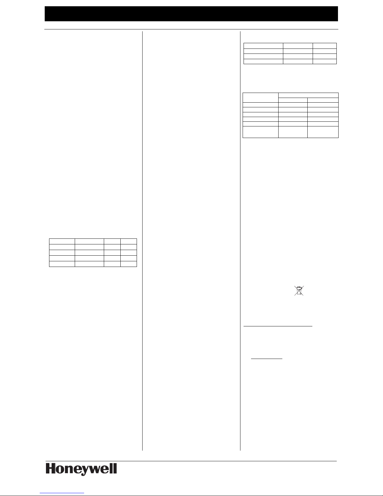
4. Configuring Sensitivity (Range)
DIP switches SENS1 and SENS2 set det ector sensitivity
(range), as shown:
SENSITIVITY RANGE * SENS1 SENS2
MAX 25 ft (7.6m)
OFF OFF
MEDIUM 15 ft (4.6m)
ON OFF
LOW 10 ft (3m)
OFF ON
LOWEST 5 ft (1.5M)
ON ON
*In order to maximize false alarm immunity, Sensitivity must be
set to match the distance between the detector and the
protected glass, as verified using the FG-701 (or GBS-7)
Glassbreak Simulator (see next page).
5. Enabling Rear Tamper
The FG1625SN is equipped with normall y-closed (NC)
cover and wall tamper switches. Each unit is shipped with
the cover tamper operational, and the wall tamper disabled.
To enable the rear tamper, remove the plastic tab on the
back of the detector, using needle-nose pliers. The wall
tamper arm will extend through the hole. Proceed with the
mounting instructions to install the wall tamper screw.
6. Mounting the Detector
Note: If ceiling mounted, the end with the hole (microphone
end) should face the glass being protected.
1. If using optional Wall Tamper: Mark the
mounting location for the wall tamper screw
based on the final location of the detector. Then,
install the wall tamper screw so that it will just
make contact with the bottom of the tamper
cavity when the unit is mounted. Use a flat head
4.2 mm or 4.8 mm screw (#8 or #10).
2. Position the unit over the wall tamper screw (if
used), then mark the mounting sc rew and wire
openings. If required by the location, install wall
anchors for the mounting screws.
3. Secure the unit to the wall or c eiling, oriented so
the microphone has the best line of sight to the
protected glass. Use 3.5 mm (#6) f lat or pan
head screws.
4. NOTE: A screw capture feature des igned to
make ceiling mounting easier will cause some
resistance when inserting the screw into the
plastic.
7. Wiring the Detector
Refer to the wiring diagram on page 1. Pul l the polling loop
wires through the center wire entry hole and connect them
to the terminal block, observing the polarity marked on the
PC board. After connecting the polling loop, allow ten
seconds for the unit to stabilize before testing.
NOTE: Accidental reverse polarity will not harm the detector
or the control.
NOTE: This sensor must be connected to a UL or ULC
Listed power supply or UL or ULC Listed control unit
capable of supplying a minimum of four hours of
standby power.
8. Address/Serial Number ID
This detector's unique, fac tory-assigned serial number can
be found on the bar code label on the PC board (see figure).
The serial number can be entered by one of the following
methods:
1. Downloading (Zone Definition screen of Compass
downloading software). Recommended for large
installations and installations where foot traffic cannot
be controlled.
2. Manually, at the "learn" prompt duri ng manual zone
programming (see Important not e below).
3. Entered by operating the detector tamper switch
twice while at the "learn" prompt during manual zone
programming.
IMPORTANT: If you are programming manually, be sure
that other polling loop sensor s are not activated so that
they cannot send a signal to the control while the
FG1625SN is being programmed (mask PIRs, don’t
open/close doors, etc.).
To enter the serial number, refer to the control’s
programming instructions, noting the following:
• Input Type = 6 (SL: Serial Number Polling Loop
Device)
• Loop Number = 1
To fault the detector when prompted, follow the
instructions under “Testing the Detector”.
9. Testing the Detector
The detector should be tested at least once each year. Test
the detector with the FG-701 (or GBS- 7) Glassbreak
Simulator. No other simulators should be used with the
FG1625SN. The detector must first be placed in Test Mode
(and you must close the cover .)
NOTE: In Test Mode, the LEDs are enabled an d detector
current can be as high as 5 mA. Be sure to exit Test Mode
on completion of testing.
To enter Test Mode manually:
1. Open the front cover.
2. Use a screwdriver to short the Test Mode pads
on the PC board (see diagram on next page).
3. Close the front cover.
The detector’s green LED blinks approximately once per
second to indicate that it has entered Test Mode.
To enter the Test Mode with the FG-701:
1. Stand within 4.6 m (15 feet) of the detec tor.
2. Switch the FG-701 to ACTIVATE and MANual
modes.
3. Point the front speaker of the glassbreak
simulator towards the detector. Press the red
START button to send a short activ ation code.
When the detector enters Tes t Mode, the green LED on
the detector flashes about once per second. If the green
LED does not flash, move closer to the detector and
repeat the procedure. Close the cover during test!
Testing the Detector (flex and audi o signals):
To test the FG1625SN:
1. Place the detector in Test Mode.
2. Set the tester switches to the TEST and FLEX
positions.
3. Position the tester near t he farthest point of the
protected glass, and point the speaker directly at
the detector. If window cover ings are present,
close them fully and hold the tester between the
coverings and the protected glass.
4. Press the red START button. The sim u la to r clicks
on and starts an 8-second armed period.
5. Generate a flex signal by c arefully striking the
glass with a cushioned tool. The tester responds
with a burst of glassbreak audi o.
If the detector receives bot h the flex and audio signals
properly, its red Alarm LED lights for five seconds.
Testing the Detector (audio signals only):
The FG-701 can also be used to test the detector’s ability
to receive audio signals only. In Test Mode, when the
detector receives the audio s ignal from the simulator, the
green Event LED flickers.
Exiting Test Mode:
Test mode will automatically time out after five minutes.
If you need to exit Test Mode sooner, exit by following
the same procedure used to enter Test Mode. The FG1625SN will automatically exit test mode 5 minutes after
the last event is detected.
10. LED Indicators
The detector is equipped with two LEDs: a green Event
LED and a red Alarm LED. Both LEDs are normally
disabled, but they are automatically enabled in Test Mode.
The following table summarizes the LED messages in
Test Mode.
CONDITION GREEN LED RED LED
Test Mode Flash once per sec OFF
Test Mode, event detected Flicker OFF
Test Mode, alarm Flash once per sec ON 5 seconds
11. Cover Screw
The front cover can be secured af ter installation. To do so,
pierce the cover breakout flash and secure the front cover
with a 2.9 mm x 6 mm (#4 x ¼”) screw.
12. Nominal Glass Thickness Chart
Nominal Thickness
Glass Type*
Minimum Maximum
Plate 3a
2mm (3/32 in.) 10mm (3/8 in.)
Tempered
3mm (1/8 in.) 10mm (3/8 in.)
Laminated1
3mm (1/8 in.) 14mm (9/16 in.)
Wired
6mm (1/4 in.) 6mm (1/4 in.)
Coated
2,3b
3mm (1/8 in.) 6mm (1/4 in.)
Sealed
Insulating
1,3b, 4
3mm (1/8 in.)
[13mm (1/2 in.)
overall]
6mm (1/4 in.)
[19mm (3/4 in.)
overall]
* Minimum size for all types is 28cm (11 in.) square; glass must be
framed in the wall or mounted in a barrier at least 0.9m (36 in.) wide.
1
Protected only if both plates in the unit are broken
2
Coated glass with security films up to 0.3mm (12 mils) thi ck (inc luding f ilms for
solar protection) may be used. Film Technologie s International , Inc. ’s
GLASS-GARD GGLL 1200 has been evaluated with this product b y
Underwriters Laboratories, Inc. at Honeywel l’s req uest
3
In compliance with Underwriters Laboratories of Canada’s Standard
for Intrusion Detection Units (CAN/ULC-S306-M89):
a. Plate glass 3mm (1/8 in.) to 10mm (3/8 in.) can be protected.
b. ULC recognizes a maximum range for protecti ng seal ed ins ulati n g
glass and coated glass of 3.8 m (12.5 ft).
4
UL recognizes a maximum range for protecting sealed insulating
glass of 6.1m (20 ft.) with sensitivity set at maximum.
13. Specifications
Range:
7.6 m (25 ft.) maximum, omni
directional
No minimum range
Operating Temper atu re:
-10° C to 55° C (14° F to
131° F)
(Indoor use environment)
Storage: -20° C to 55° C
(-4° F to 131° F)
Tamper Switch:
Combination cover/ wall
tamper
RFI Immunity:
10 V/m,
10 MHz - 1000 MHz
Power Requirements:
Input Voltage:
7 – 16 V peak-to-peak at the
polling loop terminals
Current:
1 mA max, w/ LEDs disabled
5 mA max, w/ LEDs enabled
ESD Immunity:
10 kV discharges of either
polarity to exposed surfaces
Dimensions:
115 mm x 72 mm x 27 mm
(4.5 in. H x 2.8 in. W x 1.05 in.
D)
Weight:
98 g (3.5 oz.)
Packaged Product: 126 g (4.5
oz.)
Approvals / Listings:
FCC and IC verified,
UL listed, ULC listed,
CE, C-Tick,
EN 50131-1; Security Grade 2,
Environmental Class II
Suitable for connection to an
EN60950 Limited Power
Source
Customers in
European Union
countries are
advised to dispose
of this product, at the end of
its useful life, as per
applicable local laws,
regulations and procedures.
To obtain applicable EU compliance Declaration of Conformities for this product,
please refer to our Website
http://www.security.honeywell.com/hsce/international/index.html.
For any additional information regarding the compliance of this product to any EU
specific requirements, please contact –
Quality Assurance Department,
Honeywell Security & Custom Electronics,
Newhouse Industrial Estate,
Motherwell,
Lanarkshire ML1 5SB,
Scotland,
United Kingdom
Tel: +44(0)1698 738200
Email: UK64Sales@Honeywell.com
NOTICES
FCC NOTICE: This device complies with Part 15 of the FCC Rule s. Operation is subject
to the following two conditions: (1) This deice may not cause harmful interference, and (2)
this device must accept any interference received, including interference that may cause
undesired operation.
The user is cautioned that changes or modifications not expre ssl y appro ved by H oney well
could void the user’s authority to operate this equipment.
Note: This equipment has been tested and found to comply with the lim its for a Class B
digital device, pursuant to part 15 of the FCC Rules. These limits are designed to provide
reasonable protection against harmful interference in a residential installation. This
equipment generates, uses, and can radiate radio frequency energy and, if not installed
and used in accordance with the instructions, may cause harmful interference to radio
communications. However, there is no guarantee that interference will not occur in a
particular installation. If this equipment does cause harmful interference to radio or
television reception, which can be determined by turning the equipment off and on, the
user is encouraged to try to correct the interference by one or more of the following
measures: 1) Reorient or relocate the receivin g antenna, 2) Increase the separation
between the equipment and receiver, 3) Connect the equipment into an ou tlet on a cir cuit
different from that to which the receiver is connected. The instal ler can also consult an
experienced radio/television technician for additional suggestions, if necessary.
IC Notice: This Class B digital apparatus complies with the Canadian ICES-003.
Cet appareil numérique de la Classe B est conforme à la norme NMB-003 du Canada.
 Loading...