

Page 1
Refer to Supplemental Information (next page) for complete descriptions of these installation steps
5-051-737-00 Rev C Page 1
FlexGuard® FG-1625F Glassbreak Detector Installation Instructions
FG-1625F Glassbreak Detector
FG1625F-1
MED
LOWE
ST
LOW
MA
X
S
1
=
S
E
N
S
1
S
2
=
S
E
N
S
2
S
1
=
S
E
N
S
1
S
2
=
S
E
N
S
2
S
1
=
S
E
N
S
1
S
2
=
S
E
N
S
2
S
1
=
S
E
N
S
1
S
2
=
S
E
N
S
2
ON
1
2
ON
1
2
ON
1
2
ON
1
2
FlexGuard
R
FG-1625F
Refer to manual 0-051-737-00 Rev A
for complete wiring and installation
instructions. Protected under US patent
5,524,099. Other US patents pending
2
341
CTS 206-4
O
N
TEST
PADS
SENS1
SENS2
LATCH
LCD
INSERT BLADE
AND TWIST
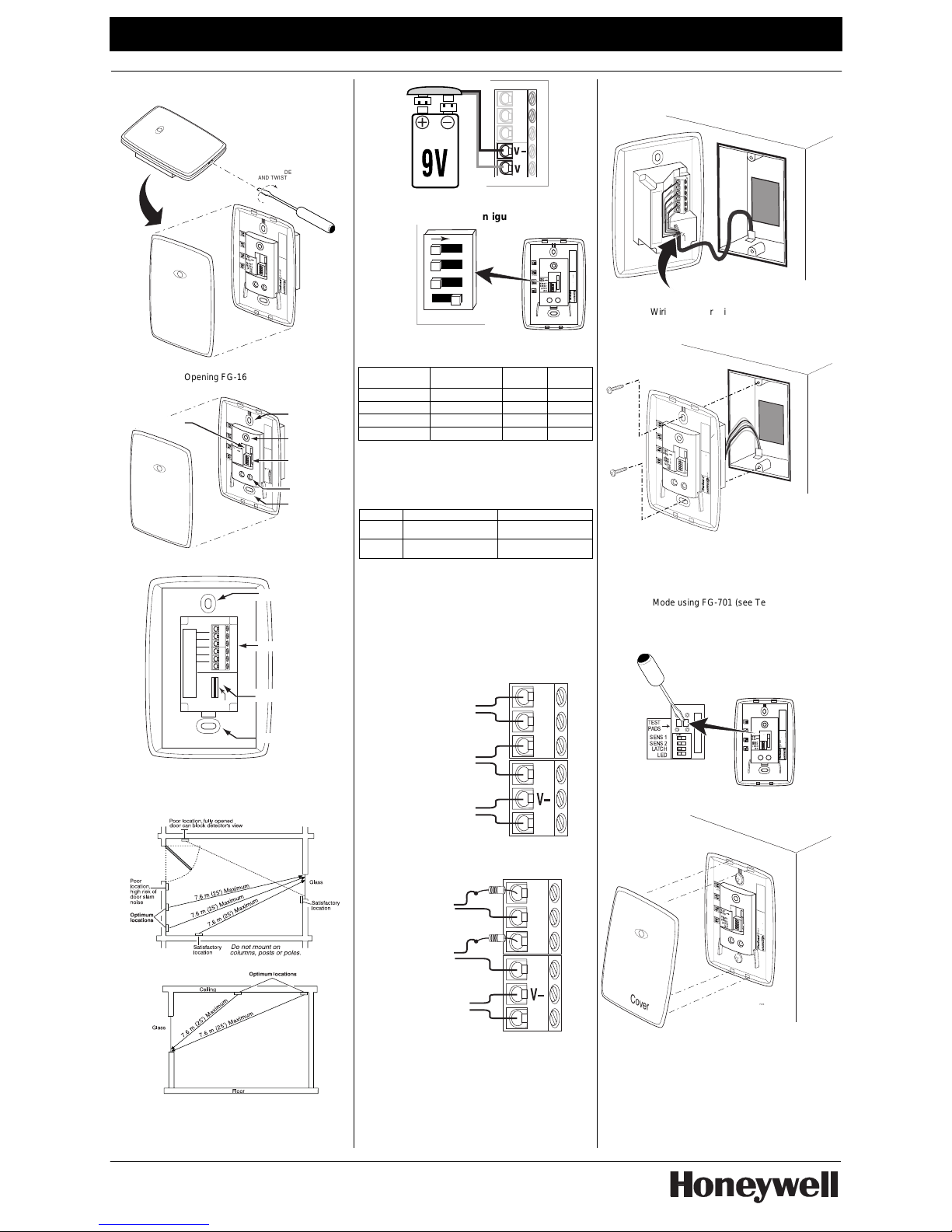
Opening FG-1625F Case
FG1625F-2
MED
LOWEST
LOW
MAX
S1 = SENS1
S2 = SENS2
S1 = SENS1
S2 = SENS2
S1 = SENS1
S2 = SENS2
S1 = SENS1
S2 = SENS2
ON
1
2
ON
1
2
ON
1
2
ON
1
2
FlexGuard
R
FG-1625F
Refer to manual 0-051-737-00 Rev A
for complete wiring and installation
instructions. Protected under US patent
5,524,099. Other US patents pending
2341
CTS 206-4
O
N
TEST
PADS
SENS 1
SENS 2
LATCH
LED
Mounting Hole
Mounting Hole
Microphone
LED Indicators
Front Cover
DIP Switch
Test Mode Pads
FG-1625F Glassbreak Detector, Front View
FG1625F-3
WIRE RESTRAINT
C
NC
V -
V +
TMPR
TMPR
Terminal Block
Mounting Hole
Wire Restraint
Mounting Hole
FG-1625F Glassbreak Detector, Back View
Select Mounting Location
Wall Mount
(T op Vie w)
FG1625F-4
FG1625F-5
Ceiling Mount: (Side View)
Test Location w/ 9V Battery
If uncertain about location or range, test the detector
before mounting using a 9V battery as shown:
V
+
V
9V
FG1625F-6
Set Sensitivity & LED Configuration
2341
CTS 206-4
O
N
TEST
PADS
SENS1
SENS2
LATCH
LED
MED
LOWEST
LOW
MAX
S1
S2
S1
S2
S1
S2
S1
S2
S1 = SENS1
S2 = SENS2
S1 = SENS1
S2 = SENS2
S1 = SENS1
S2 = SENS2
S1 = SENS1
S2 = SENS2
ON
1
2
ON
1
2
ON
1
2
ON
1
2
FlexGuard
R
FG-1625F
Refer to manual 0-051-737-00 Rev A
for complete wiring and installation
instructions. Protected under US patent
5,524,099. Other US patents pending
1
O
N
234
SENS 1
SENS 2
LATCH
LED
FG1625F-7
SENS1 & SENS2 configure sensitivity
SENSITIVITY APPROXIMATE
RANGE
SENS1 SENS2
MAX 7.6m (25 ft)
OFF OFF
MEDIUM 4.6m (15 ft)
ON OFF
LOW 3m (10 ft)
OFF ON
LOWEST 1.5m (5 ft)
ON ON
NOTE: Ranges are approximate and vary with each
room’s acoustic properties. Always verify range with an
IntelliSense FG-701 Glassbreak Simulator.
The LATCH and LED DIP switches configure LED
indicator behavior.
SWITCH OFF ON
LATCH
Red LED lights for 5
seconds during alarm
Red LED latches ON when
detector goes into alarm
1, 2
LED
LEDs disabled (except for
power up and test mode
3
)
LEDs always enabled
1
The timing of the alarm relay is not affected by the latched Alarm LED.
2
Reset the Alarm LED by removing/restorin g power, or by toggling the
detector in and out of Test Mode.
3
LEDs can be enabled/disabled using FG-701.
Connect Detector
Connect detector using 18 to 22 AWG wire, with ends
stripped approximately 6mm (1/4 in.) Use the
appropriate wiring method as shown in these diagrams:
TMPR
TMPR
C
NC
V+
1625F-8
Normally Closed Loop
Tamper Loop (NC)
Control Panel Power
Normally Closed Loop/No EOL Resistor
TMPR
TMPR
C
NC
V+
1625F-9
Normally Closed
Loop w/
EOL Resistor
Tamper Loop w/
EOL resistor
Control Panel Power
Normally Closed Loop/With EOL Resistor
Install Detector
• Test location and set Sensitivity as needed.
• Mount the junction box as appropriate.
• When wiring the detector, be sure to tie-wrap
the wires to the wire restraint loop on back of
the device (as shown below).
• Mount the detector to the junction box using
the appropriate screws (not supplied).
Junction Box
FG1625F-10
WIRE RESTRAINT
C
NC
V -
V +
TMPR
TMPR
Use Tie Wrap to attach wires to Wire Restraint
Wiring Detector/Wire Restraint Loop
Junction Box
M
E
D
L
O
W
E
S
T
L
O
W
M
A
X
S1
= SENS1
S
2 = SENS2
S
1 = S
ENS1
S2 = SENS2
S1 =
S
ENS1
S2 = SENS
2
S1 = SENS1
S2 = SENS2
ON
1
2
ON
1
2
ON
1
2
ON
1
2
FlexGuard
R
FG-1625F
Refer to manual 0-051-737-00 Rev A
for complete wiring and installation
instructions. Protected under US patent
5,524,099. Other US patents pending
2341
CTS 206-4
O
N
TEST
PADS
SENS1
SENS2
LATCH
LED
FG1625F-11
Attaching Detector to Junction Box
Test Detector Installation
Enter Test Mode using FG-701 (s ee Testing the
Detector on the next page) or manually by shorting
Test Mode pads (as below). Replace cov er before
testing the detector.
2341
CTS 206-4
O
N
TEST
PADS
SENS1
SENS2
LATCH
LED
MED
LOWEST
LOW
MAX
S1
S2
S1
S2
S1
S2
S1
S2
S1 = SENS1
S2 = SENS2
S1 = SENS1
S2 = SENS2
S1 = SENS1
S2 = SENS2
S1 = SENS1
S2 = SENS2
ON
1
2
ON
1
2
ON
1
2
ON
1
2
FlexGuard
R
FG-1625F
Refer to manual 0-051-737-00 Rev A
for complete wiring and installation
instructions. Protected under US patent
5,524,099. Other US patents pending
TEST
2341
CTS 206-4
O
N
TEST
PADS
SENS 1
SENS 2
LATCH
LED
FG1625F-12
Install Cover
Replace the cover as shown below.
M
E
D
L
O
W
E
S
T
L
O
W
M
A
X
S1 = SENS1
S2 = SENS2
S1 = SENS1
S2 = SENS2
S1 = SENS1
S2 = SENS2
S1 = SENS1
S2 = SENS2
ON
1
2
ON
1
2
ON
1
2
ON
1
2
FlexGuard
R
FG-1625F
Refer to manual 0-051-737-00 Rev A
for complete wiring and installation
instructions. Protected under US patent
5,524,099. Other US patents pending
2341
CTS 206-4
O
N
TEST
PADS
SENS1
SENS2
LATCH
LED
Front Cover
FG1625F-13
Engage top hooks first...
...engage bottom hooks last,
then snap cover into place.
Page 2
Refer to Installation Instructions and diagrams (next page) when installing this product
©2002 Honeywell International Inc. All rights reserved.
Honeywell, FlexGuard and IntelliSense are registered trademarks of
Honeywell International Inc. - All other brands mentioned are the
trademarks or registered trademarks of their respective owners.
Specifications subject to change without prior notice.
Ê5-051-737-00CaŠ
5-051-737-00 Rev C
FlexGuard® FG-1625F Glassbreak Detector Supplemental Information
1. General Information
The FG-1625F flush mount glassbreak detector senses
the sound of breaking plate, tempered, laminated, wired,
coated and sealed insulating glass.
This product is UL and ULC listed.
2. Choosing Mounting Location
The preferred mounting location for the device is on a
wall or ceiling, opposite the protected glass.
For the best detector performance, select a mounting
location that is:
• within 7.6 m (25 feet) of the protected glass;
• within clear view of the protected glass;
• at least 2 m (6.5 feet) from the floor;
• at least 1 m (3.3 feet) from forced air ducts;
• at least 1 m (3.3 feet) from sirens or bells greater
than 5 cm (2 inches) in diameter.
• between the protected glass and any heavy
window coverings that may be present.
Alternatively, when heavy window coverings are
present, the detector can be mounted on the frame
of the window.
Avoid mounting the detector on the same wall as the
protected glass, on free-standing posts or pillars, or in
rooms with noisy equipment (air compressors, bells,
power tools, etc.), if this equipment is operated when
the detector is armed.
3. Testing Mounting Location With 9V Battery
You may test the detector in the desired mounting
location before drilling/wiring. If the 9V battery cannot
supply sufficient power, the detector will not operate
and the red and green LEDs will flash on/off.
Follow the procedure described in “Testing the
Detector” (below) to confirm proper operation.
4. Configuring Sensitivity (Range)
DIP switches SENS1 and SENS2 set detector
sensitivity (range), as shown:
SENSITIVITY RANGE * SENS1 SENS2
MAX 7.6m (25 ft)
OFF OFF
MEDIUM 4.6m (15 ft)
ON OFF
LOW 3m (10 ft)
OFF ON
LOWEST 1.5M (5 ft)
ON ON
* Sensitivity must be set to match the distance between
the detector and the protected glass, as verified using
the FG-701 Glassbreak Simulator.
5. Configuring LED Switch
The LATCH and LED DIP switches determine LED
indicator operation.
SWITCH OFF ON
LATCH
Red LED lights for 5
seconds during alarm
Red LED latches ON when
detector goes into alarm
1, 2
LED
LEDs disabled (except for
power up and test mode
3
)
LEDs always enabled
1
Alarm relay timing is not affected by the latched Alarm LED.
2
Reset the Alarm LED by removing/restorin g power, or by toggling the
detector in and out of Test Mode.
3
LEDs can be enabled/disabled using FG-701.
6. Preparing Mounting Location
The FG-1625F is designed for flush mounting using a
standard US or Canadian electrical junction box. Once
you have selected the appropriate mounting location,
install a junction box.
7. Wiring the Detector
Refer to the wiring diagrams (page 1) to select the
appropriate wiring configuration.
NOTE: This sensor must be connected to a UL Listed
power supply or UL Listed control unit capable of
supplying a minimum of four hours of standby power.
8. Mounting the Detector
Using appropriate screws (not supplied), mount the
detector to the junction box. When not using a
junction box, use wall anchors for mounting in sheet
rock.
9. Testing the Detector
The detector should be tested at least once each year.
Test the detector with the FG-701 Glassbreak Simulator.
The model FG-700 Glassbreak Simulator can also be
used if it is set for the TEMPered glass sound. Other
simulators will not give accurate indication of range.
Always test detector with cover in place.
To enter Test Mode manually:
1. Remove the front cover.
2. Use a screwdriver to short the Test Mode
pads on the PC board (see diagram on next
page).
3. Close the front cover.
The detector’s green LED blinks approximately once per
second to indicate that it has entered Test Mode.
To enter the Test Mode with the FG-701:
1. Stand within 4.6 m (15 feet) of the detector.
2. Switch the FG-701 to ACTIVATE and MANual
modes.
3. Point the front [speaker] of the glassbreak
simulator towards the detector. Press the red
START button to send a short activation code.
When the detector enters Test Mode, the green LED
on the detector flashes about once per second. If the
green LED does not flash, move closer to the detector
and repeat the procedure.
Testing the Detector (flex and audio signals):
To test the detector using the FG-701:
1. Place the detector in Test Mode.
2. Set the FG-701 switches to the TEST and
FLEX positions.
3. Position the FG-701 near the farthest point of
the protected glass, and point the speaker
directly at the detector. If window coverings
are present, close them fully and hold the FG701 between the coverings and the protected
glass.
4. Press the red START button. The simulator
clicks on and starts an 8-second armed
period.
5. Generate a flex signal by carefully striking the
glass with a cushioned tool. The FG-701
responds with a burst of glassbreak audio.
If the detector receives both the flex and audio signals
properly, its red Alarm LED lights for five (5) seconds.
(Red Alarm LED does not latch in Test Mode).
Testing the Detector (audio signals only):
The FG-701 can also be used to test the detector’s
ability to receive audio signals only. See the FG-701
Operating Instructions for additional information. When
it receives the audio signal, the detector flickers its
green Event LED.
Exiting Test Mode:
When you have finished testing, exit Test Mode by
following the same procedure used to enter Test Mode.
The FG-1625F automatically exits Test Mode five
minutes after the last event is detected.
10. LED Indicators
The detector is equipped with two LEDs: a green Event
LED and a red Alarm LED. When the LEDs are
enabled, they light in a variety of patterns to indicate
the detector's status. The following table summarizes
the LED messages.
CONDITION GREEN LED RED LED
Normal OFF OFF
Normal, event detected Flicker OFF
Normal, break detected OFF ON 5 seconds
Normal, alarm latched OFF ON
Power up ON 1 second ON 1 second
Low Voltage Flash ON/OFF Flash ON/OFF
Test Mode Flash once per sec OFF
Test Mode, event detected Flicker OFF
Test Mode, alarm Flash once per sec ON 5 seconds
11. Remote LED Enable/Disable Mode
The detector’s Remote LED Enable/Disable Mode allows
you to enable or disable the detector’s LEDs with the
FG-701 Glassbreak Simulator.
To enable or disable the LEDs with the FG-701:
1. Set LED switch, S4 position 4, to off.
2. Enter Test Mode, and then exit Test Mode.
3. Within two (2) seconds, enter Test Mode
again; this changes LED enable/disable status.
4. Exit Test Mode again.
5. Clap your hands to test the LEDs. If enabled,
the green LED will flicker. If disabled, the
green LED will remain off.
12. Specifications
Range:
7.6 m (25 ft.) maximum, omnidirectional
No minimum range
Operating Temperature:
-10° to 50° C (14° to 122° F)
Storage: -20° to 50° C
(-4° to 122° F)
Alarm Duration:
5 seconds (unaffected by
alarm LED latching)
Alarm Relay:
FG-1625F Form A
125 mA maximum
25 VDC maximum
ON/closed 22Ω ±1Ω
OFF/open >1MΩ
Tamper Switch:
Cover tamper
25 mA maximum
24 VDC maximum
RFI Immunity:
30 V/m,
10 MHz - 1000 MHz
ESD Immunity:
10 kV discharges of either
polarity to exposed surfaces
Power Requirements:
6 - 18 VDC; 12 mA typical at
12 VDC, 22 mA max, (Latched
LED) AC Ripple: 4 Volts
peak-to-peak at Nominal 12
VDC
Dimensions:
Face Plate: 125 x 84 x 70mm
(4.9 in. H x 3.3 in. W x 0.53 in. D)
Rear Housing
:
70 x 42mm
(2.8 in. H x 1.6 in. W)
Weight:
98 g (3.5 oz.)
Packaged Product: 126 g ( 4.5 o z.)
Approvals / Listings:
FCC and IC verified
UL Listed, ULC Listed
CE, C-Tick
EN 50131-1; Security Grade
2, Environmental Class II
Suitable for connection to an
EN60950 Class II Limited
Power Source
13. Nominal Glass Thickness Chart
Nominal Thickness
Glass Type*
Minimum Maximum
Plate
3a, 3b, 4
2mm (3/32 in.) 10mm (3/8 in.)
Tempered
3mm (1/8 in.) 10mm (3/8 in.)
Laminated 3b
3mm (1/8 in.) 14mm (9/16 in.)
Wired
6mm (1/4 in.) 6mm (1/4 in.)
Coated
2,3b
3mm (1/8 in.) 6mm (1/4 in.)
Sealed Insulating
1,5
3mm (1/8 in.)
[13mm (1/2 in.)
overall]
6mm (1/4 in.)
[19mm (3/4 in.)
overall]
* Minimum size for all types is 28cm (11 in.) square; glass must be
framed in the wall or mounted in a barrier at least 0.9m (36 in.) wide.
1
Protected only if both plates in the unit are broken
2
Coated glass with security films up to 0.35mm (14 mils) thick (including
films for solar protection) may be used. Evaluated with the these
products: 3M
®
SCOTCHSHIELD® SH14CLARL – 0.35mm (14 mils), 4
ply film; Film Technologies International, Inc.’s GLASS-GARD GGLL
1200 has been evaluated with this product by Underwriters
Laboratories, Inc.
3
In compliance with Underwriters Laboratories of Canada’s Standard
for Intrusion Detection Units (CAN/ULC-S306-M89):
a. Plate glass 3mm (1/8 in.) to 10mm (3/8 in.) can be used.
b. ULC recognizes a maximum range for protecting coated, 3mm
(1/8 in.) laminated, and 2mm (3/32 in.) plate glass of 3.8m
(12.5 ft.); sensitivity should be set at maximum.
4
Minimum of 3mm (1/8 in.) plate glass is to be used in UL installations.
5
UL recognizes a maximum range for protecting seal e d insulating
glass of 6.1m (20 ft.) with sensitivity set at maximum.
NOTICES
FCC NOTICE: This device complies with Part 15 of the FCC Rules.
Operation is subject to the following two conditions: (1) This deice may
not cause harmful interfer ence, and (2) this device must accept any
interference received, inclu ding inter ference th at may c ause und esired
operation.
The user is cautioned th at changes or modifications not expressly
approved by Honeywell could v oid the user’s authority to operate this
equipment.
NOTE: This equi pment as been teste d and found to comply wit h the
limits for a Class B digital device, pursuan t to Part 15 of the FCC
Rules. These limits are design ed to provide reasonable protection
against harmful interference in a residential installation. This
equipment generates, uses and can radiate radi o frequency energy
and, if not installed and use d in accor dance with t he instruct ions, may
cause harmful interference to r adio communications. H owever, there
is no guarantee that interference will not occur in a particular
installation. If this equipment doe s cause harmf ul interf erenc e to radio
or television reception, which can be determined by turning the
equipment off and on, the user is encoura ged to try to correct the
interference by one or more of the followi ng measures: 1 ) Reorient o r
relocate the receiving antenn a; 2) incr ease t he s epara tion betw ee n the
equipment and receiver; 3) connect th e equipment into an outl et on a
circuit different from that to w hich the r eceiver is connecte d; 4) consul t
the dealer or an experienced radio/television technician for help.
IC Notice: This Class B digital appara tus compli es with t he Canadi an
ICES-003.
Cet appareil numérique de la Classe B est conforme à la norme NMB003 du Canada
 Loading...