

Honeywell F-BO-AFE70, F-BO-AFE70-3, F-BO-AFE70-2 Installation, Connection, Commissioning, Maintenance
Page 1

FIRE ALARM ASPIRATION SENSING TECHNOLOGY™
Automatic Purging Units for
Aspirating Detectors
F-BO-AFE70
Description
Installation - Connection - Commissioning - Maintenance
SYSTEM SENSOR EUROPE
Pittway Tecnologica S.r.l.
Via Caboto 19/3
34147 TRIESTE
Italy
www.systemsensoreurope.com
Page 2

Page 3
User Manual Series F-BO-AFE70
Important information for the installer for the use of a Purging unit
in a fire detection system
Fire detection systems are designed to protect people and property from the dangers of a fire.
Therefore, they have to be planned, installed and put into operation very carefully by trained personnel.
For the handling of compressed air or for the installation of a compressed-air system, country-specific qualifying examinations or approvals may be required. In addition, for the installation, commissioning and maintenance of the Automatic Purging Units F-BO-AFE70, you must follow the
special precautions listed below.
Before starting any work on the Purging unit, the supply voltage of the Purging unit as well
as the compressed-air supply must be reliably interrupted, and measures must be taken to
ensure that they are not switched back on!
Only turn on the compressed-air supply after finishing all mounting, installation, connection and parameterisation work in the course of commissioning, as described starting on
page 40 in Chapter 10: „Commissioning and function test“. Turning on the compressed-air
supply at an earlier time can result in serious personal injuries or damage to property,
depending on the condition of the system and the environment.
When carrying out any work, do wear suitable personal protective gear, for example, wear
eye protection and hearing protection when working with compressed air.
3
Take care that fingers, other parts of the body, and objects never get into the pipe connection openings. During the Purging process, the valve that is integrated into the Automatic
Purging Units F-BO-AFE70 is closed with high velocity and great force. As a result, parts of
the body or objects, which are in the valve body, can be seriously injured or even severed or
destroyed respectively! In addition, the Purging unit can be severely damaged or destroyed
as a result.
Only expert service specialists and trained employees are allowed to plan, install, modify, maintain and service a fire detection system.
Fire detection and/or extinguishing systems must be checked and serviced regularly by trained
personnel in order to maintain their functionality, on the one hand, and to avoid false alarms to
the greatest extent possible on the other.
Parts of a fire detection or extinguishing system that are experiencing a fault, are not able to perform their functions efficiently or can not do so at all. Therefore, faults must be repaired immediately by a trained and authorized specialised company.
In addition to the careful and expert manipulation, the safe operation of aspirating smoke detectors
requires, above all, the proper transport, storage, installation and commissioning.
The special requirements for the installation of a fire detection system are not described in this User
Manual.
Safety instructions
Before installing, commissioning, servicing or using the product described in this User
Manual, you have to read the User Manual carefully and, in particular, you have to
note and subsequently follow the information given on pages 3 and 4 as well as in
Chapter 1.5: „Important tips“ from page 8 onwards.
Furthermore, the pictographs that are described in Chapter 1.3: „Types of symbols“
from page 8 onwards are very important for you – these pictographs are used frequently throughout the User Manual to remind you of dangers that may arise in case
of improper use of the product, as well as to point to valuable tips.
I56-4252-010
D200-104-00
Page 4

4
User Manual Series F-BO-AFE70
Pressure Equipment / CE-labelling / Construction Products Regulation
Within the EU, pressure equipment is subject to the Directive 2014/68/EU of the European Parliament and of the Council of 15 May 2014 on the harmonisation of the laws of the member states
regarding making pressure equipment available on the market. In Austria the guideline has been
implemented with the Druckgeräteverordnung (DGVO), in Germany it has been implemented with
the „Vierzehnte Verordnung zum Produktsicherheitsgesetz (Druckgeräteverordnung –
14. ProdSV)“.
According to §8 of the DGVO, the Automatic Purging Units F-BO-AFE70 are pressure equipment
with low risk potential, and according to article 4, paragraph 3 of the Directive 2014/68/EU they
are „Pressure equipment and assemblies below or equal to the limits set out in points (a), (b) and
(c) of paragraph 1 and in paragraph 2 respectively (...)“ and are designed and manufactured in
accordance with the engineering practice of a Member State.
The CE-labelling results from a guideline from the board of the European Community for the equivalency of the laws of its member states, including the mutual approval of laws. By means of the
CE-label that is affixed to the device, the manufacturer confirms the conformity of the product with
the following standards and guidelines:
Electromagnetic Compatibility Directive: 2014/30/EU, EN 55022:2010, EN 50130-4:2011 +
A1:2014.
The CE-labelling of the device expressly does not result from the guideline 2014/68/EU.
You must not exceed the values specified in the project planning guidelines of the
aspirating smoke detector. Please observe the respective national standards and
guidelines for planning aspirating smoke detectors.
However, the Automatic Purging Units F-BO-AFE70 do not represent an additional air resistance in the sampling pipe network, and therefore they do not have
to be additionally included in the calculation of the sampling pipe network.
I56-4252-010
D200-104-00
Page 5

User Manual Series F-BO-AFE70
Contents
1 Introduction..........................................................................................................................7
1.1 General............................................................................................................................................7
1.2 Intended use.................................................................................................................................... 7
1.3 Types of symbols............................................................................................................................8
1.4 Abbreviations, special terms...........................................................................................................8
1.5 Important tips..................................................................................................................................8
1.6 Scope of delivery............................................................................................................................9
2 Manner of operation of a Purging unit............................................................................10
2.1 General..........................................................................................................................................10
2.2 Characteristic features of the Automatic Purging Unit F-BO-AFE70............................................11
3 Displaying of the operating conditions and operation....................................................12
3.1 Operating conditions indicated by the status LED........................................................................12
3.2 Operation by the user....................................................................................................................13
3.3 Operation by the installer..............................................................................................................13
4 Pneumatic components – dimensioning...........................................................................14
4.1 Purging unit...................................................................................................................................14
4.2 Compressed-air supply..................................................................................................................15
5
5 Final assembly, mechanical structure and dimensions...................................................19
5.1 Final assembly..............................................................................................................................19
5.2 Mechanical structure.....................................................................................................................20
5.3 Dimensions...................................................................................................................................21
6 Safety devices......................................................................................................................22
7 Special notes on using the F-BO-AFE70-3 in refrigeration areas..................................23
8 Mounting and connection of pneumatic components.....................................................24
8.1 Location of installation.................................................................................................................24
8.1.1 Permissible mounting positions..................................................................................................24
8.1.2 Installation of the Automatic Purging Unit F-BO-AFE70..........................................................25
8.2 Connection to the sampling pipe and to the aspirating smoke detector.........................................25
8.2.1 Loosening the pipe connection...................................................................................................26
8.2.2 Use of filters............................................................................................................................... 26
8.2.3 Use of check valves....................................................................................................................27
8.2.4 Connection diagram for a double pipe system............................................................................27
8.2.5 Connection diagram for far-flung pipe systems with master-slave mode of the Purging units. . .28
8.3 Connection of the compressed air.................................................................................................29
9 Connection and parameterisation.....................................................................................30
9.1 General instructions......................................................................................................................30
9.2 Power supply................................................................................................................................31
9.3 Location of the display and operating elements and terminals on the control board of the
Automatic Purging Unit F-BO-AFE70..........................................................................................31
9.4 Connection of and interaction between Purging unit, aspirating smoke detector and fire detection
control panel.................................................................................................................................31
9.4.1 Standard connection with indirect actuation through the fire detection control panel (in
accordance with EN 54-13)........................................................................................................33
9.4.1.1 Output „Slave activation“ ...................................................................................................... 33
9.4.1.2 Synchronisation of the internal clock of the F-BO-AFE70 .................................................... 34
9.4.2 Connection of Purging units in the master-slave mode with direct actuation through the fire
detection control panel (in accordance with EN 54-13)..............................................................34
9.5 Parameterisation of the Purging unit.............................................................................................36
9.5.1 Setting the Purging program.......................................................................................................36
9.5.2 Internal clock..............................................................................................................................37
9.5.2.1 Displaying and manually setting the time .............................................................................. 37
I56-4252-010
D200-104-00
Page 6

6
User Manual Series F-BO-AFE70
9.5.2.2 Automatically synchronising the time .................................................................................... 38
9.5.3 Setting and displaying the device number..................................................................................38
9.6 Label showing the parameterisation options and connection possibilities.....................................39
10 Commissioning and function test......................................................................................40
11 Inspection............................................................................................................................42
12 Specifications......................................................................................................................43
13 Set parameters....................................................................................................................45
14 Appendix A..........................................................................................................................46
14.1 EU declaration of conformity........................................................................................................46
14.2 Supplier's declaration of conformity.............................................................................................47
I56-4252-010
D200-104-00
Page 7
User Manual Series F-BO-AFE70 Chapter 1 • Introduction
1 Introduction
1.1 General
This User Manual of the Automatic Purging Units F-BO-AFE70 provides the expert installer with
the information necessary for planning, configuration, installation, connection, parameterisation,
commissioning and maintenance of the Automatic Purging Units Series F-BO-AFE70.
The manner of operation of Purging units in general and of the Automatic Purging Units
F-BO-AFE70 in particular are described from page 10 onwards in Chapter 2: „Manner of operation of a Purging unit“.
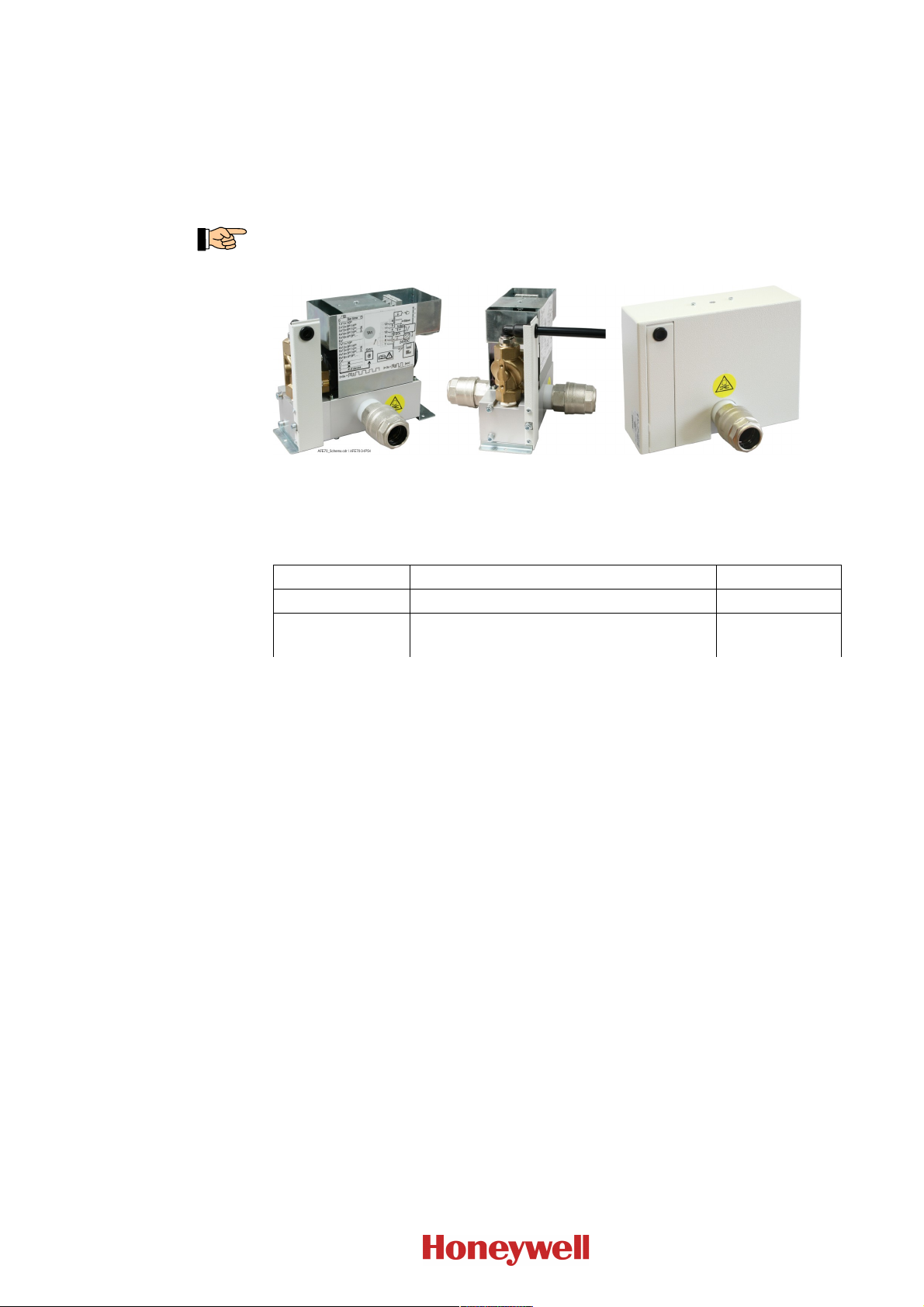
Fig. 1: View of the Automatic Purging Unit F-BO- AFE70
Left: Automatic Purging Unit F-BO-AFE70-3 without cover
Centre: Automatic Purging Unit F-BO-AFE70-3 view of the solenoid valve
Right: Automatic Purging Unit F-BO-AFE70-3 with cover
7
The following types of the Automatic Purging Units F-BO-AFE70 are available:
Type Name Art. No.
F-BO-AFE70-2 Automatic Purging Unit/3500L/IP54
F-BO-AFE70-3 Automatic Purging
Unit/5000L/DF/IP54
1) IP54 means: protected against dust in harmful quantities, complete protection against contact,
protection against water splashed from all directions
2) DF ... refrigeration area down to -20°C
Table 1: Type code of the Automatic Purging Units Series F-BO- AFE70
1) 2)
1)
F-BO-AFE70-2
F-BO-AFE70-3
The Automatic Purging Units F-BO-AFE70-2 and F-BO-AFE70-3 have outer dimensions and functionality in common, they essentially differ in the built-in solenoid valves which allow different air
flow rates and/or extended operating temperatures. The Automatic Purging Unit F-BO-AFE70-2
with a typical air flow rate of the solenoid valve of approx. 3,500 l/min (ANR) at 0.7MPa (7bar) is
designed both for small as well as for larger pipe systems with a large number of aspiration holes.
Thanks to the solenoid valve's typical air flow rate of approx. 5,000 l/min (ANR) at 0.7MPa (7bar),
the Automatic Purging Unit F-BO-AFE70-3 is suitable for even larger and further-flung pipe systems, and in addition it allows use in environments with low temperatures (down to -20°C). Notes
with regard to dimensioning can be found from page 14 onwards in Chapter 4: „Pneumatic components – dimensioning“. The functions of the Purging units are described starting on page 10 in
Chapter 2: „Manner of operation of a Purging unit“.
The information in this User Manual relates to the firmware release number PL0200_V_1.00 of the
control board. In Fig. 11 the position of the label is indicated where the version of the firmware
used can be read. Devices using firmware with another release number can differ in their function
from the range of functions described in this document.
1.2 Intended use
The Automatic Purging Units F-BO-AFE70 are designed and intended exclusively for purging
pipes of aspirating smoke detectors for fire detection systems in buildings, within the limits
described in this User Manual. Any other use of the devices is expressly not intended and forbidden.
I56-4252-010
D200-104-00
Page 8
8
Chapter 1 • Introduction User Manual Series F-BO-AFE70
The improper use of the Automatic Purging Unit F-BO-AFE70 can endanger life and health
or lead to damage to property. The manufacturer does not accept any responsibility for
improper use.
1.3 Types of symbols
Especially important sections of text in this User Manual are indicated with symbols. The following symbols are used:
Means DANGER! Ignoring these directions can result in danger to life and health.
Means ATTENTION! Ignoring these tips can result in system malfunctions or damage to prop-
erty.
Means TIP! Here the text contains tips for easier operation.
Means that the country-specific and/or the site-specific requirements of the DEVICE and/or
SYSTEM APPROVALS of the fire detection system must be observed.
1.4 Abbreviations, special terms
In order to improve the readability of this User Manual, the generic terms „Purging unit“ and
„F-BO-AFE70“ are used, and the exact type F-BO-AFE70-2 or F-BO-AFE70-3 is specified only if
it is necessary.
The terms „control board“ and AFS70-1 refer to the built-in electronic control of the Purging unit.
The term „overpressure“ refers to the difference between the static absolute pressure of the com-
pressed air and the static absolute pressure of the ambient air. In colloquial language, this is usually
referred to as „pressure“.
„ANR“ means that the specification applies to standard reference atmosphere (at a pressure of
0.1MPa (1bar), a temperature of 20°C and a relative air humidity of 65%).
In this User Manual, the term „aspirating smoke detector“ (which is also abbreviated as „ASD“)
refers both to
the actual evaluation unit of an ASD
as well as sometimes also to
the combination of the essential components of which an ASD consists, namely, the evaluation
unit, the ASD, the sampling pipe system and sometimes the compressed-air supply, etc.
In the context it is always clear what is meant in the particular case.
The fire detection control panel is also abbreviated as „FDCP“.
„PLC“ is the abbreviation for programmable logic controller.
Further abbreviations that are not familiar in everyday usage are avoided in this User Manual.
1.5 Important tips
Fire detection systems and their components must always be planned, installed and put into operation by specialists who are trained on a continuous basis. The specific specialist training on the
functions of the aspirating smoke detectors must be provided by the respective manufacturer or by
persons expressly authorized by the manufacturer for this purpose. Since the Purging unit will be
integrated directly into the pipe system of the ASD, the guidelines of the manufacturer of the ASD,
with regard to the construction and length of the pipe system, must be observed.
The devices that are used in addition to the ASD, such as the fire detection control panel, the power
supply, etc., are only mentioned as examples in this User Manual. The present manual does not
provide any information concerning the expert planning or design of a fire detection system. It
replaces neither the installer's required technical qualification nor his or her specific training.
I56-4252-010
D200-104-00
Page 9
User Manual Series F-BO-AFE70 Chapter 1 • Introduction
Pay attention to the danger notices given on page 3.
Beware of static charges! The electronic components used in the Automatic Purging Units
F-BO-AFE70 can be destroyed by static charges when the device is open. Before and during the
work being performed on printed circuit boards, static charges from your body must be reliably
discharged by touching an earthed piece of metal.
1.6 Scope of delivery
The Automatic Purging Units F-BO-AFE70 are assembled at the factory and supplied 100% function-tested. Only the pipe connecting parts have been enclosed for reasons of safe transport and still
have to be installed. Please check the delivery for completeness and transport damage before
assembling the equipment.
The delivery scope of the Automatic Purging Unit F-BO-AFE70 includes:
the valve block (with flange-mounted solenoid valve) that has been mounted on the bottom
plate and has been completely assembled and tested, including the mounted control board
AFS70-1, with protection cover (i.e., the housing) and cover.
two 25mm push-in fittings for the connection to the sampling pipe
two pipe nipples G3/4“×34mm
two plastic gaskets Ø32mm×10mm
this User Manual
an end-of-line resistor 5.6kOhm (for the line-monitoring of the fault output of the evaluation
unit of the aspirating smoke detector)
mounting material (three screws and three 6mm plugs for wall mounting)
three cable ties
transport packaging.
9
The Purging unit weighs approx. 3.2kg – the sturdy transport packaging has been designed to
avoid transport damage to any part. If the packaging has been damaged, you must inspect the
Purging unit especially thoroughly.
I56-4252-010
D200-104-00
Page 10
10
Chapter 2 • Manner of operation of a Purging unit User Manual Series F-BO-AFE70
2 Manner of operation of a Purging unit
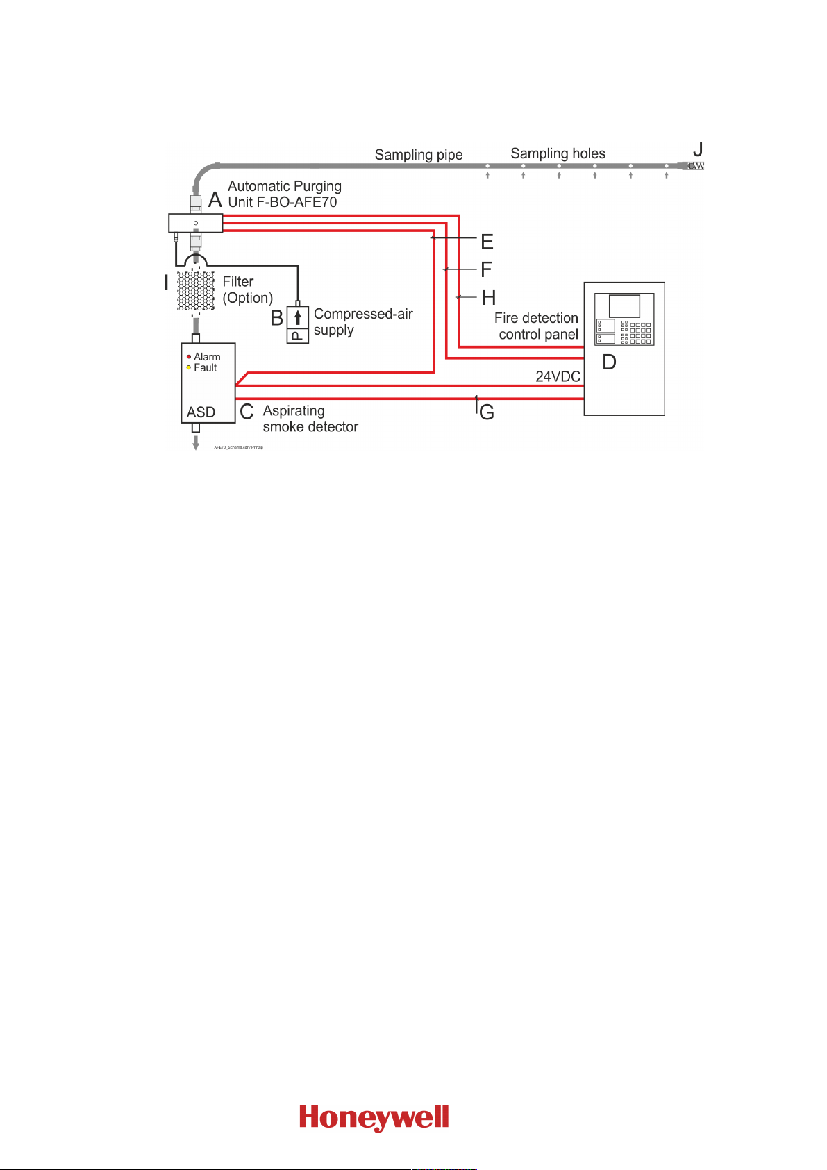
Typical structure of a system, consisting of fire detection control panel, aspirating smoke detector,
Purging unit, compressed-air supply and sampling pipe.
Fig. 2: Depiction of the structure of a system with an Automatic Purging Unit F-BO- AFE70 as well as
2.1 General
Aspirating smoke detectors use a low negative pressure to continuously sample air through aspiration holes of a sampling pipe that is laid in a room or building, and direct the air samples to a central measuring element (the evaluation unit) in order to examine the sample for various characteristics (e.g., the smoke concentration).
the required components and connections
A … Automatic Purging Unit F-BO- AFE70
B … Compressed-air supply
C … Aspirating smoke detector; in the above diagram an ASD with one pipe is shown, note that
for each pipe system a separate Purging unit is needed.
D … Fire detection control panel
E … Power supply line. Both the Purging unit as well as the ASD must be supplied with 24VDC.
F … Transmission of the fault message of the ASD to the fire detection control panel
G … Transmission of the fire alarm of the ASD to the fire detection control panel. The connection
can be established – as shown in the figure above – by means of a conventional line or via
loop modules.
H … The fire detection control panel actuates or activates the F-BO- AFE70
I … Air filter (optional), which can be located before the Purging unit. As a result, on the one
hand the Purging unit is protected against contamination, and on the other hand every Pur-
ging process also cleans the filter. If this is not possible (for example, because the filter case
is not pressure-resistant), the filter must be located between the Purging unit and the aspir-
ating smoke detector.
J … Check valve
Over the operating time, continuously aspirating the ambient medium through the relatively small
aspiration holes and a pipe network with a relatively small cross-sectional area leads to an accumulation of contaminations which can change the aspirated air flow and can even result in the measurement failing completely. In order to prevent this contamination, dirty pipe networks and filter
systems should be regularly cleaned („purged“) by means of compressed air.
For this purpose, clean compressed air is manually or automatically led into the pipe network
and/or the filter system at intervals. In order to protect the evaluation unit of the aspirating smoke
detector against damage caused by exposure to compressed air, in conventional Purging units first a
valve isolates the evaluation unit from the pipe network, and then compressed air is led into the
pipe network through a second valve that is connected to a T-piece.
I56-4252-010
D200-104-00
Page 11

User Manual Series F-BO-AFE70 Chapter 2 • Manner of operation of a Purging unit
2.2 Characteristic features of the Automatic Purging Unit F-BO-AFE70
In contrast to the structure of conventional Purging units, the Automatic Purging Unit F-BO-AFE70
only needs one (built-in) solenoid valve; furthermore, thanks to its thoughtful design, the Automatic Purging Unit F-BO-AFE70 ensures completely unhindered air flow from the sampling pipe
through the Purging unit to the evaluation unit of the ASD. The unit is controlled by an integrated
control board which has been developed for this special task and which replaces the PLC that is
normally used.
Thanks to the use of high-quality materials and the high-precision processing, the Automatic Purging Unit F-BO-AFE70 is designed to ensure flawless operation for many years.
The trouble-free operation can be affected by various environmental influences, such as temperature, humidity and air that is polluted by gases and aerosols, which can cause increased need for
maintenance and reduce the life span due to wear and tear or contamination.
The following features distinguish the Automatic Purging Unit F-BO-AFE70:
6 Purging programs, each with short or long Purging cycle
they can be manually controlled by means of an external push-button
internal clock for up to 6 daily timed, preventive Purging processes
automatic start if fault message is received from aspirating smoke detector
remote-controlled start (e.g., based on external calendar of factory or office hours)
if there are several F-BO-AFE70's, a time delay can be used so as not to stress the com-
pressed-air system
master-slave mode with actuation of one or more „slaves“
monitoring of the supply voltage
they can be used in a wide pressure range, F-BO-AFE70-2 up to 0.7MPa (7bar) and
F-BO-AFE70-3 up to 1.0MPa (10bar)
they are prepared for connection to all usual fire detection control panels, either via conven-
tional lines or via loop modules.
11
I56-4252-010
D200-104-00
Page 12
YYY
Y
12
Chapter 3 • Displaying of the operating conditions and operation User Manual Series F-BO-AFE70
3 Displaying of the operating conditions and operation
This chapter describes how the individual operating conditions of the Purging unit are indicated
and explains the respective operational features.
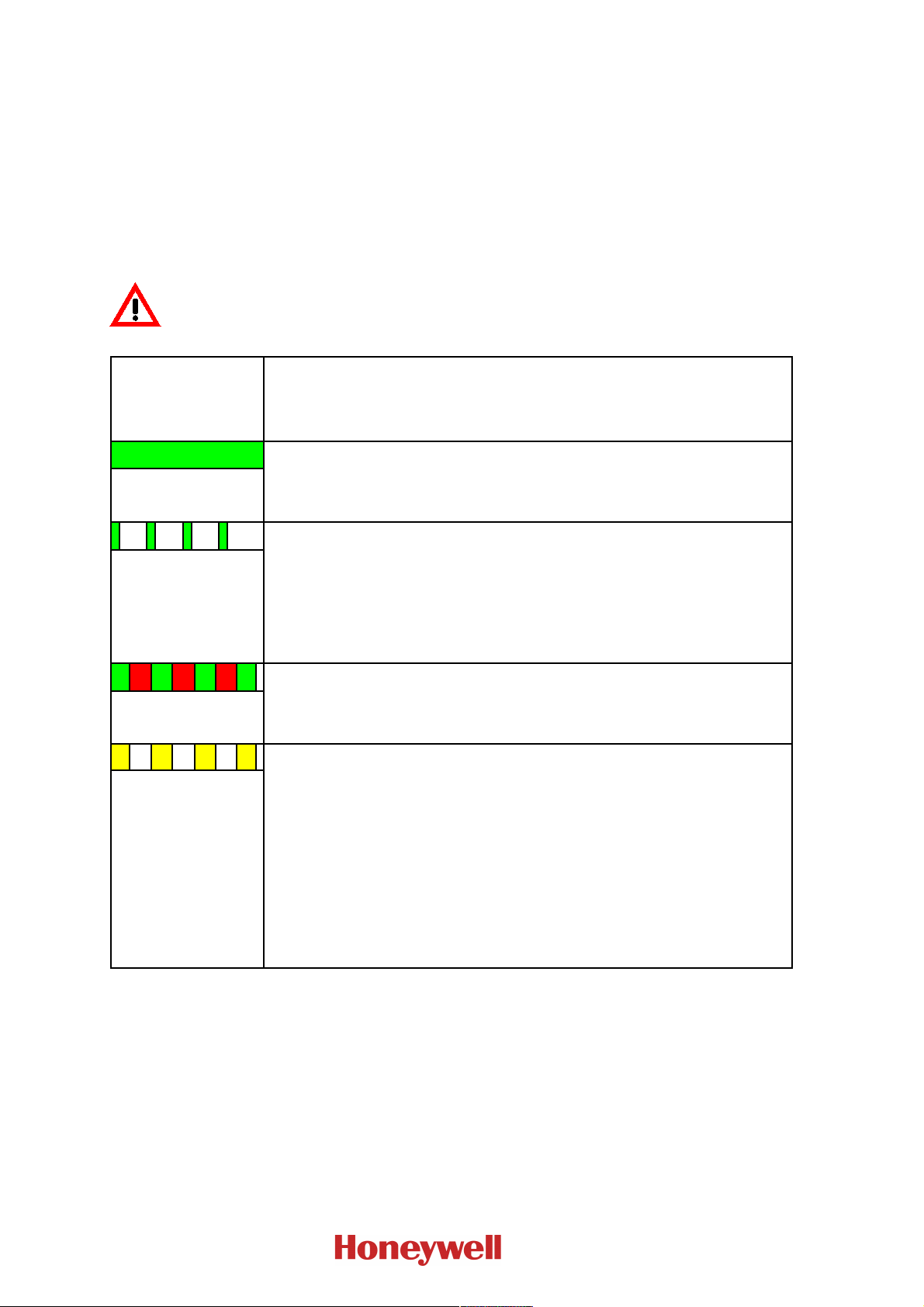
3.1 Operating conditions indicated by the status LED
The control board of the Purging unit continuously checks the status and indicates it in red, yellow
and green, by means of the status LED (see Fig. 5 on page 21).
The conditions that are indicated by the status LED are explained below in Table 2.
If the status LED is dark it is very likely that the Purging unit experiences a power failure or, if it
has been proven that the supply voltage is available, the componentry itself experiences a fault.
In any case you must assume that the Purging unit is inoperable. The fault must be removed as
soon as possible.
Condition of the
status LED
G = green, R = red
Y = yellow
G Condition: Normal condition
illuminates green
Condition of the control board / response time / effect / removal
Response time: Immediately
Effect: Componentry is in normal operation
Removal: Not necessary
↑=G flashing green
G R G R G R G
alternately green and
red
blinking yellow
Condition: No valid Purging program selected
Response time: Immediately
Effect: The componentry is all right, however it will not carry out an automatic
Purging process.
HINT: Switch position 0 allows you to set the time, switch position F allows you to
set the device number.
Removal: Select a valid Purging program.
Condition: The solenoid valve has been activated.
Response time: Immediately
Effect: The Purging process is currently running.
Removal: Not necessary
Condition: Either the aspirating smoke detector reports a fault, or a wire breakage
on the connection line from the Purging unit (terminals 3 and 4) to the aspirating
smoke detector has been detected.
Response time: Immediately
Effect: If the aspirating smoke detector reports a fault, the selected Purging process
will be started.
The aspirating smoke detector could be partly or completely out of order and therefore must be checked.
If the connection line is broken, this will be evaluated like a fault message from the
aspirating smoke detector.
Removal: If there is no fault of the aspirating smoke detector, the connection line
must be checked for freedom from faults.
I56-4252-010
D200-104-00
Page 13
User Manual Series F-BO-AFE70 Chapter 3 • Displaying of the operating conditions and operation
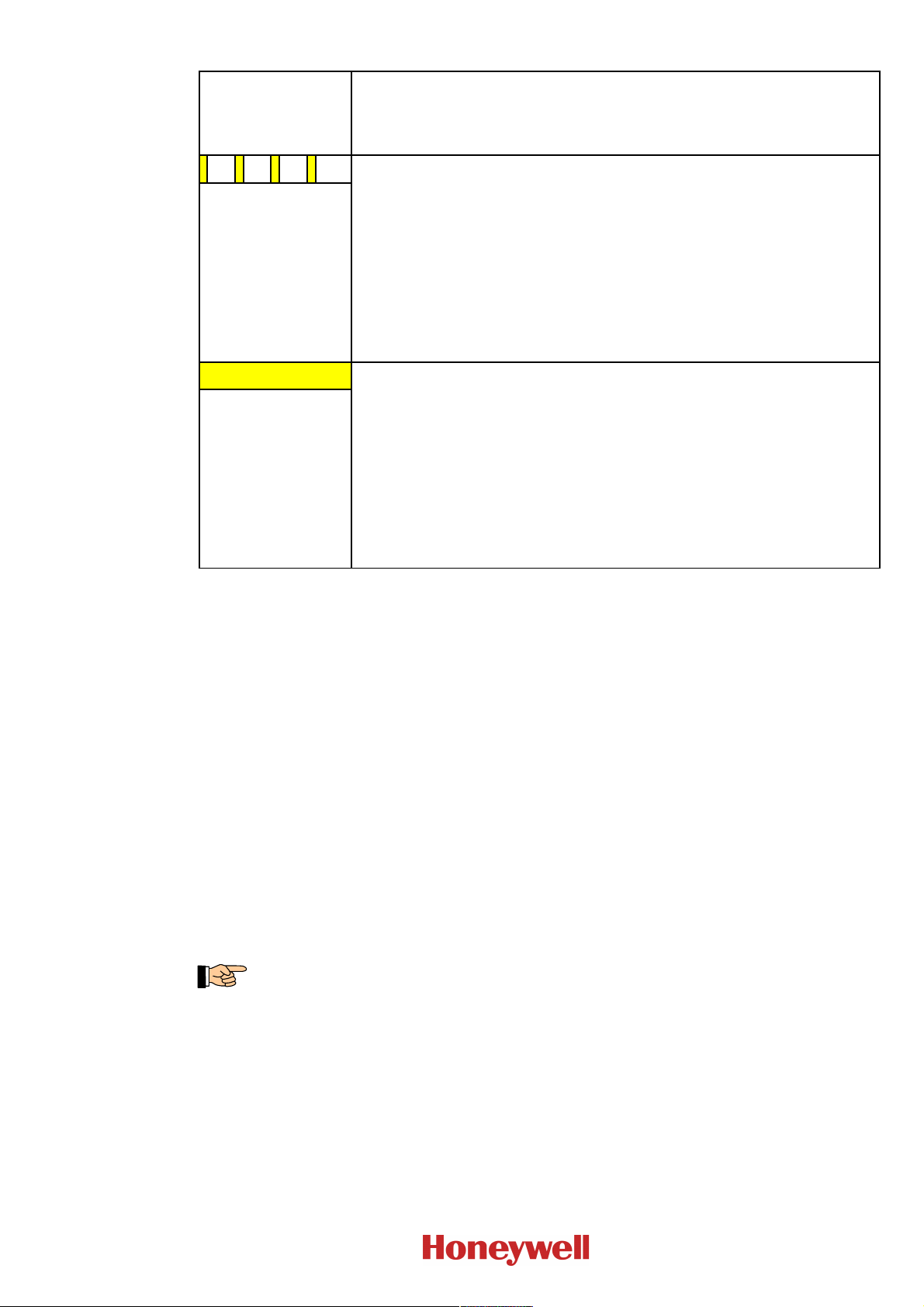
Condition of the
status LED
G = green, R = red
Y = yellow
flashing yellow
Y Condition: There is a fault.
illuminates yellow
Condition of the control board / response time / effect / removal
Condition: A short circuit on the connection line to the fault contact of the aspirat-
ing smoke detector has been detected.
Response time: Immediately
Effect: If the Purging unit is synchronised by an external timer and the short circuit
exists for approx. 60 seconds, the internal clock will be synchronised to 00:00.
If the short circuit exists for less than 50 seconds, this will be indicated by the
status LED, but apart from that it will not be evaluated. If the short circuit exists
for more than 70 seconds, this will be evaluated as fault, the condition of the status
LED will change to illuminating yellow.
Removal: If the time has not been synchronised, the connection line must be
checked.
Response time: Immediately
Effect: Maybe the aspirating smoke detector is partly or completely out of order
and must be checked.
Removal: If an air flow fault of the aspirating smoke detector exists, further
manual Purging processes should be carried out in order to remove the clogging
(see on page 31 in Chapter 9.3: „Location of the display and operating elements
and terminals on the control board of the Automatic Purging Unit F-BO-AFE70“).
If there is another fault, it must be removed on the aspirating smoke detector.
If there is no fault of the aspirating smoke detector, the connection line must be
checked for freedom from faults.
13
Table 2: Possible conditions of the componentry status display
3.2 Operation by the user
If a valid Purging program has been set on the Purging unit, the unit operates in the automatic mode
and the status LED indicates the current condition.
In this case the Purging processes will be carried out automatically. If additional Purging processes
are needed, you can carry them out by pressing the external push-button „Manual activation“,
provided that this feature has been prepared by the installer of the system. In this case, the compressed air will be blown into the pipe network for as long as the push-button is being pressed, but
the maximum duration for one press of the push-button is limited to 2 minutes.
3.3 Operation by the installer
If a valid Purging program (Purging program „1“ … „C“) has been set on the Purging unit, additional Purging processes can be started manually.
A manual Purging process can be started by briefly pressing the button TA1; depending on the Purging program that has been set with the rotary switch „Purging program“ SW1, this will carry out a
long or short Purging process.
The button TA1 will only be accessible after removing the cover (see Fig. 4 on page 20).
I56-4252-010
D200-104-00
Page 14
2.00 3.15 4.00 12.57 6.00 28.28
2.10 3.47 4.10 13.21 6.10 29.23
2.20 3.81 4.20 13.86 6.20 30.20
2.30 4.16 4.30 14.53 6.30 31.18
2.40 4.53 4.40 15.21 6.40 32.17
2.50 4.91 4.50 15.91 6.50 33.19
2.60 5.31 4.60 16.62 6.60 34.22
2.70 5.73 4.70 17.35 6.70 35.26
2.80 6.16 4.80 18.10 6.80 36.32
2.90 6.61 4.90 18.86 6.90 37.40
3.00 7.07 5.00 19.64 7.00 38.49
3.10 7.55 5.10 20.43 7.10 39.60
3.20 8.05 5.20 21.24 7.20 40.72
3.30 8.56 5.30 22.07 7.30 41.86
3.40 9.08 5.40 22.91 7.40 43.01
3.50 9.63 5.50 23.76 7.50 44.18
3.60 10.18 5.60 24.64 7.60 45.37
3.70 10.76 5.70 25.52 7.70 46.57
3.80 11.35 5.80 26.43 7.80 47.79
3.90 11.95 5.90 27.34 7.90 49.02
Diameter
[mm]
Area
[mm²]
Diameter
[mm]
Area
[mm²]
Diameter
[mm]
Area
[mm²]
14
Chapter 4 • Pneumatic components – dimensioning User Manual Series F-BO-AFE70
4 Pneumatic components – dimensioning
4.1 Purging unit
The geometry of the sampling pipe and the number and size of the aspiration holes depends on the
size and geometry of the room as well as the technical possibilities of the aspirating smoke detector
used. Thanks to the special construction of the Automatic Purging Unit F-BO-AFE70, it does not
cause an additional air resistance in the piping that is worth mentioning, and therefore it does not
have to be taken into consideration when dimensioning the pipe system.
Through intensive tests and experiments, the recommended values for dimensioning that are stated
below, have been established. Please note that the specified values are only approximate values
because a huge number of components (the length and the geometry of the pipe, the position of the
aspiration holes along the piping, the opening pressure of a check valve that may exist, etc.) affect
the Purging process. Therefore you can only make sure that the Purging unit is working properly by
carrying out a final test on the individual system.
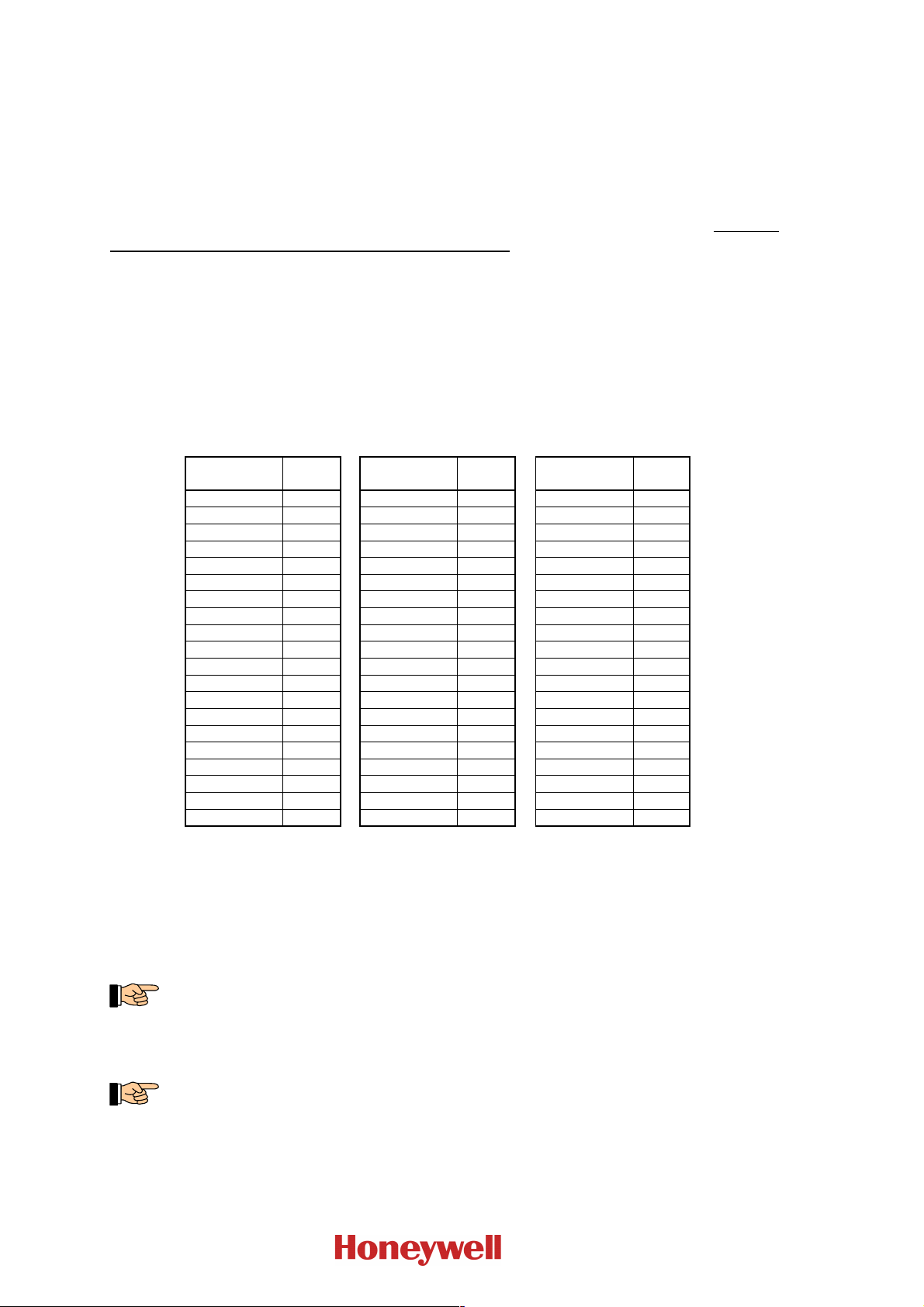
First calculate the total aperture area of the aspiration holes that exist in the pipe network. In order
to keep the calculation simple, the table below shows the area of a circular hole, depending on its
diameter.
Table 3: Calculation aid for the determination of the total aperture area of the aspiration holes in the
sampling pipework; add up the stated values for the holes in the piping that is to be connected to
the Purging unit. The diameters that have been marked in bold in the table are the predetermined
standard values for the Series FAAST and VESDA.
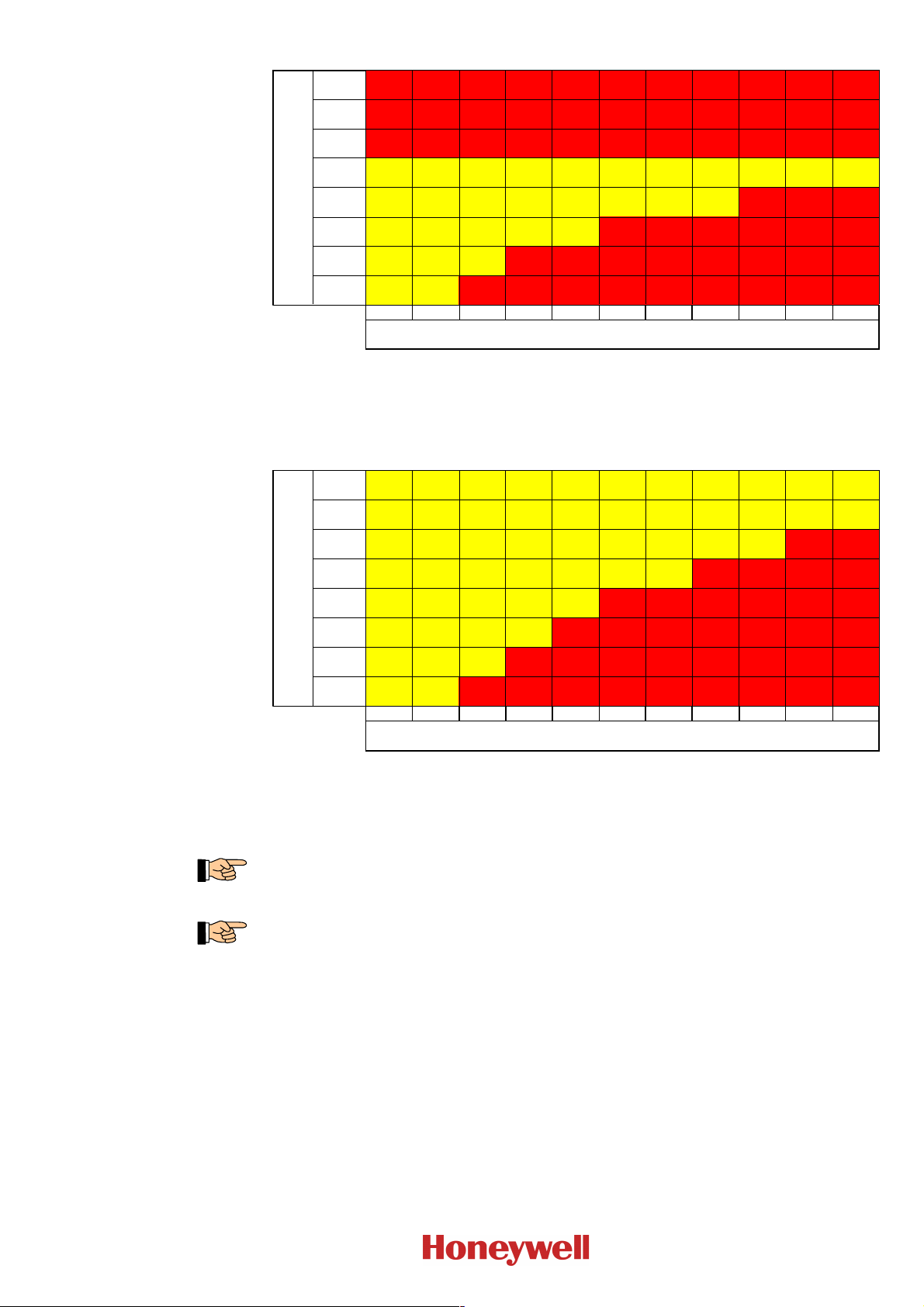
The tables below show the operation limits of the Automatic Purging Units F-BO-AFE70-2 and
F-BO-AFE70-3, depending on the input overpressure during the Purging process and on the sum of
the aperture area of the aspiration holes of the piping that is connected to the Purging unit.
The data is based on a DN25 pipe network that has been realised as straight branch, and on a
check valve with an opening pressure of 25kPa (0.25bar) that has been installed at the end of the
pipe network. A safety factor has been added to the data and therefore it can be regarded as
approximate value for normal system configurations, but the proper functioning of the respective
system must always be verified in a test!
During the Purging process, the input overpressure decreases, depending on the quality of the
compressed-air supply and the air volume that is consumed. The input overpressure value listed
in the table is the value when air is being consumed, i.e., the decreased value!
I56-4252-010
D200-104-00
Page 15
User Manual Series F-BO-AFE70 Chapter 4 • Pneumatic components – dimensioning
- - - - - - - - - - -
- - - - - - - - - - -
- - - - - - - - - - -
- - -
- - - - - -
- - - - - - - -
- - - - - - - - -
40mm² 60mm² 80mm² 100mm² 120mm² 140mm² 160mm² 180mm² 200mm² 220mm² 240mm²
Eingangsüberdruck
input overpressure
1.00MPa
(10bar)
0.90MPa
(9bar)
0.80MPa
(8bar)
0.70MPa
(7bar)
AFE70-2
(3500L)
AFE70-2
(3500L)
AFE70-2
(3500L)
AFE70-2
(3500L)
AFE70-2
(3500L)
AFE70-2
(3500L)
AFE70-2
(3500L)
AFE70-2
(3500L)
AFE70-2
(3500L)
AFE70-2
(3500L)
AFE70-2
(3500L)
0.60MPa
(6bar)
AFE70-2
(3500L)
AFE70-2
(3500L)
AFE70-2
(3500L)
AFE70-2
(3500L)
AFE70-2
(3500L)
AFE70-2
(3500L)
AFE70-2
(3500L)
AFE70-2
(3500L)
0.50MPa
(5bar)
AFE70-2
(3500L)
AFE70-2
(3500L)
AFE70-2
(3500L)
AFE70-2
(3500L)
AFE70-2
(3500L)
0.40MPa
(4bar)
AFE70-2
(3500L)
AFE70-2
(3500L)
AFE70-2
(3500L)
0.30MPa
(3bar)
AFE70-2
(3500L)
AFE70-2
(3500L)
gesamte Öffnungsfläche
total aperture area
- -
- - - -
- - - - - -
- - - - - - -
- - - - - - - -
- - - - - - - - -
60mm² 90mm² 120mm² 150mm² 180mm² 210mm² 240mm² 270mm² 300mm² 330mm² 360mm²
Eingangsüberdruck
input overpressure
1.00MPa
(10bar)
AFE70-3
(5000L)
AFE70-3
(5000L)
AFE70-3
(5000L)
AFE70-3
(5000L)
AFE70-3
(5000L)
AFE70-3
(5000L)
AFE70-3
(5000L)
AFE70-3
(5000L)
AFE70-3
(5000L)
AFE70-3
(5000L)
AFE70-3
(5000L)
0.90MPa
(9bar)
AFE70-3
(5000L)
AFE70-3
(5000L)
AFE70-3
(5000L)
AFE70-3
(5000L)
AFE70-3
(5000L)
AFE70-3
(5000L)
AFE70-3
(5000L)
AFE70-3
(5000L)
AFE70-3
(5000L)
AFE70-3
(5000L)
AFE70-3
(5000L)
0.80MPa
(8bar)
AFE70-3
(5000L)
AFE70-3
(5000L)
AFE70-3
(5000L)
AFE70-3
(5000L)
AFE70-3
(5000L)
AFE70-3
(5000L)
AFE70-3
(5000L)
AFE70-3
(5000L)
AFE70-3
(5000L)
0.70MPa
(7bar)
AFE70-3
(5000L)
AFE70-3
(5000L)
AFE70-3
(5000L)
AFE70-3
(5000L)
AFE70-3
(5000L)
AFE70-3
(5000L)
AFE70-3
(5000L)
0.60MPa
(6bar)
AFE70-3
(5000L)
AFE70-3
(5000L)
AFE70-3
(5000L)
AFE70-3
(5000L)
AFE70-3
(5000L)
0.50MPa
(5bar)
AFE70-3
(5000L)
AFE70-3
(5000L)
AFE70-3
(5000L)
AFE70-3
(5000L)
0.40MPa
(4bar)
AFE70-3
(5000L)
AFE70-3
(5000L)
AFE70-3
(5000L)
0.30MPa
(3bar)
AFE70-3
(5000L)
AFE70-3
(5000L)
gesamte Öffnungsfläche
total aperture area
Table 4: Operation limits of the Automatic Purging Unit F-BO- AFE70-2, depending on the input pres-
sure that is available during the Purging process („input overpressure“) and the sum of the aperture areas of the piping that is to be connected to the Purging unit („total aperture area“). The
Automatic Purging Unit F-BO-AFE70-2 must not be operated with input overpressures of more
than 0.7MPa (7bar)!
15
Table 5: Operation limits of the Automatic Purging Unit F-BO- AFE70-3, depending on the input pres-
sure that is available during the Purging process („input overpressure“) and the sum of the aperture areas of the piping that is to be connected to the Purging unit („total aperture area“). The
Automatic Purging Unit F-BO-AFE70-3 must not be operated with input overpressures of more
than 1.0MPa (10bar)!
The Automatic Purging Unit F-BO-AFE70 still works perfectly at and below an input overpressure of 0.1MPa (1bar), but perhaps the resulting pressure built up in the pipe network will not
suffice to open the check valve and to clean the pipe network completely.
If the sum of the area of the aspiration holes of the piping exceeds the specified values, branches
can also be purged, by means of the master-slave mode (see from page 34 onwards in Chapter
9.4.2: „Connection of Purging units in the master-slave mode with direct actuation through the
fire detection control panel (in accordance with EN 54-13)“), through separate Automatic Purging Units F-BO-AFE70. This also applies analogously to the areas marked with „-“ in the
Tables 4 and 5.
4.2 Compressed-air supply
I56-4252-010
D200-104-00
The required size of the air vessel as well as the air delivery volume of the compressed-air supply
essentially depend on the following factors:
positive operating pressure of the compressed-air supply (air vessel overpressure)
chosen input overpressure of the Purging unit
total opening time of the solenoid valve during the Purging process.
Page 16

16
Chapter 4 • Pneumatic components – dimensioning User Manual Series F-BO-AFE70
There is a tool based on a spreadsheet which makes this dimensioning easier. In order to use it,
you need the following parameters:
- Ambient temperature
- Number of aspiration holes
- Diameter of aspiration holes
- Air vessel overpressure
- Actual input overpressure
The compressed air must always be clean and free from oil and water or other contamination. If
compressed air is used which is not sufficiently purified, these contaminations can result in malfunctions of the Purging unit or of the aspirating smoke detector. For example, the valve piston
system of the Purging unit can ice up or the measuring device of the aspirating smoke detector
can become oily, and therefore can become useless or can even be destroyed. This can also lead
to false alarms or increased contamination of the aspirating smoke detector as a result of particles
in the compressed air, which are again drawn in by the evaluation unit of the aspirating smoke
detector after a Purging process.
Metal shavings, other foreign particles or liquids in compressed-air lines must not get into the
Purging unit because otherwise the Purging unit can be damaged.
As recommended value for the purity of compressed air, Class 2 according to ISO8573-1:2010
should be used, which for oil permits a limit value of max. 0.1mg/m³ of compressed air. This
value also makes sense with regard to the durability of the compressed-air lines.
During the Purging process the Automatic Purging Units Series F-BO-AFE70 briefly need a very
large amount of air which is withdrawn from the compressed-air vessel of the compressed-air supply. The air output capacity of a compressor is only of secondary importance for the dimensioning
of the compressed-air supply of the Purging unit because usually the time between two Purging
processes is very long and therefore the compressor has sufficient time for charging the compressed-air vessel. Therefore, only the dimensioning of the compressed-air vessel is dealt with
below.
Fig. 3: Typical construction of a compressed-air system for providing the required compressed-air
volume of an Automatic Purging Unit Series F-BO- AFE70, and explanation of the terms used in
this chapter and by the calculation tool.
A … Air vessel overpressure: This is the pressure that prevails in the compressed-air vessel – as
well as the reference value that has been set on the compressor and at which the compressor
should turn itself on again.
B … Input overpressure: This is the pressure at the Purging unit's input (compressed-air connec-
tion) that results from the number and size of aspiration holes, from the flow rate of the
solenoid valve that has been installed in the Purging unit, as well as from the pressure
losses in the compressed-air supply pipe.
C … Pressure regulator (option): The pressure regulator SHOULD be used whenever the avail-
able air vessel overpressure is markedly higher than the recommended input overpressure,
and MUST be used whenever the air vessel overpressure is higher than the maximum input
overpressure of the F-BO- AFE70 used.
If several Purging units are supplied by the same compressed-air vessel, it is also possible
to use one pressure regulator for several Purging units. But in this case, please note the
maximum possible flow rate of the pressure regulator.
Tables 6 and 7 contain approximate values for the calculation of the minimum size of the compressed-air vessel of the compressed-air system, depending on the air vessel overpressure and the
chosen input overpressure of the respective Purging unit. The result of the table is given in litres
per second of operation of the solenoid valve, and therefore it still has to be multiplied by the
I56-4252-010
D200-104-00
Page 17

User Manual Series F-BO-AFE70 Chapter 4 • Pneumatic components – dimensioning
solenoid valve's operation time during a Purging process, in order to obtain the size of the air vessel.
The prerequisite for the validity of the tables in this chapter is a constant input overpressure of
the Purging unit during the Purging process; to ensure this an appropriately dimensioned pressure-limiting valve is required.
The calculation of the stated values is based on a pipe between compressed-air vessel and Purging unit that is very short and has a low velocity loss. Therefore, if the distances are large, see to
it that the compressed-air supply pipe is generously dimensioned in order to keep the pressure
losses low.
In order to estimate the required size of the compressed-air vessel, proceed as follows:
First determine on the basis of the specifications in Chapter 4.1 the required input overpressure of
the Purging unit.
Now use Table 6 or 7 to determine the air vessel's required sub volume (in litres per second of the
Purging process) at the intersection of the Purging unit's required input overpressure and the available air vessel overpressure. For the required total vessel volume you have to multiply the determined size by the solenoid valve's planned total opening time during the Purging process.
An example should explain the approach:
For your system you need an F-BO-AFE70-2 with an input overpressure of at least 0.5MPa (5 bar).
Furthermore, your planned air vessel overpressure of the compressor is 1.0MPa (10bar).
17
So, to determine the size of the compressed-air tank for an Automatic Purging Unit F-BO-AFE70-2
you use Table 6. The Purging unit's required input overpressure of 0.5MPa (5bar) and the air vessel
overpressure of the compressor of 1.0MPa (10bar) result in a vessel sub volume of 9.4 litres per
second of opened solenoid valve.
Depending on the Purging process that is to be set according to Chapter 9.5.1 in the course of commissioning, the solenoid valve's total opening time during the Purging process amounts to 3×3=9
seconds (for the short Purging process) or 5×5=25 seconds (for the long Purging process).
So in the case of the short Purging process and an air vessel overpressure of 1.0MPa (10bar), an air
vessel volume of at least 9.4×9=84.6 litres is needed, in the case of the long Purging process an air
vessel volume of at least 9.4×25=235 litres is needed.
I56-4252-010
D200-104-00
Page 18

1.4 2.4 3.4 4.8 6.7 9.2 12.4
- - -
1.5 2.6 3.8 5.5 7.8 11.0 15.5 - - -
1.7 3.0 4.3 6.4 9.4 13.8 20.6
- - -
1.9 3.4 5.0 7.7 11.7 18.4 30.9 - - -
2.2 3.9 6.0 9.6 15.6 27.5 61.7
- - -
2.5 4.7 7.5 12.8 23.4 55.0 - - - -
3.0 5.9 10.0 19.2 46.7
- - - - -
3.8 7.8 15.0 38.4 - - - - - -
5.0 11.7 30.0
- - - - - - -
7.5 23.4 - - - - - - - -
15.0
- - - - - - - - -
- - - - - - - - - -
Kesselüberdruck
air vessel overpressure
1.2MPa
(12bar)
1.1MPa
(11bar)
1.0MPa
(10bar)
0.9MPa
(9bar)
0.8MPa
(8bar)
0.7MPa
(7bar)
0.6MPa
(6bar)
0.5MPa
(5bar)
0.4MPa
(4bar)
0.3MPa
(3bar)
0.2MPa
(2bar)
0.1MPa
(1bar)
0.1MPa
(1bar)
0.2MPa
(2bar)
0.3MPa
(3bar)
0.4MPa
(4bar)
0.5MPa
(5bar)
0.6MPa
(6bar)
0.7MPa
(7bar)
0.8MPa
(8bar)
0.9MPa
(9bar)
1.0MPa
(10bar)
Eingangsüberdruck F BO AFE70‑ ‑ ‑2
input overpressure F BO AFE70‑ ‑ ‑2
1.7 2.5 4.1 6.3 8.8 12.5 17.7 25.0 37.8 62.5
1.8 2.8 4.6 7.1 10.3 15.0 22.1 33.3 56.7 125.0
2.0 3.1 5.2 8.3 12.3 18.8 29.4 50.0 113.3 -
2.3 3.6 6.1 10.0 15.4 25.0 44.2 100.0 - -
2.6 4.2 7.3 12.5 20.6 37.5 88.3 - - -
3.1 5.0 9.2 16.7 30.8 75.0 - - - -
3.7 6.3 12.2 25.0 61.7 - - - - -
4.6 8.3 18.3 50.0 - - - - - -
6.1 12.5 36.7 - - - - - - -
9.2 25.0 - - - - - - - -
18.3 - - - - - - - - -
- - - - - - - - - -
Kesselüberdruck
air vessel overpressure
1.2MPa
(12bar)
1.1MPa
(11bar)
1.0MPa
(10bar)
0.9MPa
(9bar)
0.8MPa
(8bar)
0.7MPa
(7bar)
0.6MPa
(6bar)
0.5MPa
(5bar)
0.4MPa
(4bar)
0.3MPa
(3bar)
0.2MPa
(2bar)
0.1MPa
(1bar)
0.1MPa
(1bar)
0.2MPa
(2bar)
0.3MPa
(3bar)
0.4MPa
(4bar)
0.5MPa
(5bar)
0.6MPa
(6bar)
0.7MPa
(7bar)
0.8MPa
(8bar)
0.9MPa
(9bar)
1.0MPa
(10bar)
Eingangsüberdruck F-BO-AFE70-3
input overpressure F-BO-AFE70-3
18
Chapter 4 • Pneumatic components – dimensioning User Manual Series F-BO-AFE70
Table 6: Estimate of the minimum size of the compressed-air vessel, depending on the air vessel overpres-
sure and the required input overpressure of the Automatic Purging Unit F-BO- AFE70- 2. The
values are given in litres per second of operation of the solenoid valve.
Table 7: Estimate of the minimum size of the compressed-air vessel, depending on the air vessel overpres-
sure and the required input overpressure of the Automatic Purging Unit F-BO- AFE70- 3. The
values are given in litres per second of operation of the solenoid valve.
I56-4252-010
D200-104-00
Page 19

User Manual Series F-BO-AFE70 Chapter 5 • Final assembly, mechanical structure and dimensions
5 Final assembly, mechanical structure and dimensions
5.1 Final assembly
For reasons of safe transport, the pipe connecting components are enclosed and still have to be
installed.
Figure 4 gives an overview of the structure of a Purging unit after final assembly.
In order to assemble the device, proceed as follows:
Remove the two M3 screws from the cover and lift the cover of the Purging unit.
Screw a pipe nipple G3/4“×34mm by hand into the thread of the 25mm push-in fitting as far as it
will go and completely push the plastic gasket Ø32mm×10mm onto the pipe nipple.
Remove the protective cover from an opening of the housing; keep the protective cover for later
use.
Now screw the part of the pipe nipple's thread that protrudes from the plastic gasket by hand into
one of the two fitting threads of the Purging unit's body as far as it will go.
Use a wrench of the right size (wrench size 32mm) to turn the 25mm push-in fitting by approxim-
ately another 30° until it seats tightly and seals perfectly.
19
Repeat the procedure described above for the other side of the Purging unit.
Cover the openings of the 25mm push-in fittings with the protective covers and only remove the
protective covers just before connecting the sensor pipe network.
By carrying out this step, the final assembly has been completed.
It must be ensured that after final installation of the Purging unit, no push-in fitting can be
loosened by hand, and that all push-in fittings are perfectly sealed. Therefore, check the
tight seat of the push-in fittings after final assembly and prior to commissioning.
You must never use any glue for the connections of the sampling pipes on the Purging unit and
on the aspirating smoke detector.
The warranty claims shall terminate in case of violation of this rule.
I56-4252-010
D200-104-00
Page 20

20
Chapter 5 • Final assembly, mechanical structure and dimensions User Manual Series F-BO-AFE70
5.2 Mechanical structure
Fig. 4: View of the Automatic Purging Unit F-BO- AFE70 with cover taken off
Left: Automatic Purging Unit F-BO-AFE70-3 without cover
Right: Cover that has been removed from the Purging unit
A … Valve block
B … Compressed-air connection
C … Piping to the aspirating smoke detector
D … Control board AFS70-1
E … Cover of the Purging unit
F … Opening for the cable entry
G … Button TA1
I56-4252-010
D200-104-00
Page 21

User Manual Series F-BO-AFE70 Chapter 5 • Final assembly, mechanical structure and dimensions
5.3 Dimensions
21
Fig. 5: Dimensions of the Automatic Purging Unit F-BO- AFE70
A … Front view
B … View from below
C … View from the left side
D … Piping to the monitored area
E … Piping to the aspirating smoke detector
F … Position of the opening for the cable entry
G … Compressed-air connection F-BO-AFE70- 2
H … Compressed-air connection F-BO-AFE70- 3
I … Status LED
I56-4252-010
D200-104-00
Page 22

22
Chapter 6 • Safety devices User Manual Series F-BO-AFE70
6 Safety devices
By installing the Automatic Purging Unit F-BO-AFE70 in the customer's pipe network, and
through the connection to the other components also provided by the customer, namely the aspirating smoke detector, the fire detection control panel, the electrical power supply as well as the compressed-air supply, a machine in the sense of the Directive 2006/42/EC is created.
Therefore the adherence to this directive must be ensured during the whole installation; therefore
corresponding measures have to be taken which depend on the system construction, the installed
components as well as the use of the building, and which can also exceed the minimum requirements listed below. Therefore a corresponding danger evaluation is required in any case.
The following basic minimum requirements must always be fulfilled in any case and at any time:
A protection against contact with the movable valve piston of the Purging unit must be in place;
this requirement is fulfilled if both 25mm push-in fittings have been installed as described in
Chapter 5.1: „Final assembly“ and suitable pipes of the customer's pipe system have been inserted in such a way that it is not possible to enter and touch the valve piston without a tool, also
compare Chapter 8.2: „Connection to the sampling pipe and to the aspirating smoke detector“.
The possibility that the compressed air that is introduced into the pipe system during the Pur-
ging process can eject parts which can cause injuries or damage to property, must have been
prevented altogether. This can be done, for example, by altogether preventing such parts from
entering the compressed-air system or the piping, or by making sure that at the time of the Purging process nobody can stay in the danger zone, or by implementing other suitable protective
measures (e.g., deflectors) in the system.
All parts that will be pressurised during operation (for example, pipes, fittings, valves, hoses,
pressure regulators and filters) must have been approved for the application of compressed air
within the pressure range that is to be expected.
A device must be installed by means of which the system can be easily shut down both in the
event of an emergency as well as during normal operation. This is ensured, for example, if the
compressed-air supply to the Automatic Purging Unit F-BO-AFE70 can be interrupted easily
and quickly by means of a hand-actuated pneumatic valve. This valve must be freely accessible
and has to be appropriately labelled or signposted with „EMERGENCY STOP“.
If, in spite of all the safety precautions and protective measures that have been taken, unavoidable
risks still exist, the necessary warnings and warning devices have to be put up.
A failure to meet the requirements described here can have serious consequences for life,
limb and property; therefore make sure that all required devices are in place and function
flawlessly.
I56-4252-010
D200-104-00
Page 23

User Manual Series F-BO-AFE70 Chapter 7 • Special notes on using the F-BO-AFE70-3 in refrigeration areas
7 Special notes on using the F-BO-AFE70-3 in refrigeration areas
The problem in refrigeration areas is that due to condensation and ice formation, ice crystals can
form on aspiration holes and in the sampling pipe and have to be blown out regularly.
The place of installation of the Purging unit must be chosen such that condensation is precluded at
all times.
After installing the Purging unit at the place where it will be used, you have to wait until the Purging unit has become acclimatised to the ambient temperature of the refrigeration area before you
connect it. For this purpose it is recommended that the cover of the Purging unit be removed and
the two protective covers of the 25mm push-in fittings be removed (if they have been installed).
Take care that contaminants or foreign objects can not get into the push-in fittings.
After acclimatisation to the final ambient temperature, the two 25mm push-in fittings have to be
checked for tight seat and, if necessary, they have to be tightened up. Only after that is the Purging
unit to be electrically connected and mechanically connected to the sensor pipe network and to the
compressed-air system, according to the instructions provided in the chapters that follow.
In particular, make sure that only dried compressed air is used for the operation of the Purging unit,
because residual humidity in the compressed air can lead to icing of the Purging unit.
Please note the demands on the compressed air, see Chapter 4.2: „Compressed-air supply“ from
page 15 onwards.
23
The sampling pipe must have the same temperature as the refrigeration area.
I56-4252-010
D200-104-00
Page 24

24
Chapter 8 • Mounting and connection of pneumatic components User Manual Series F-BO-AFE70
8 Mounting and connection of pneumatic components
This chapter describes the mounting of the Purging unit, the connection to the sampling pipe system as well as the aspirating smoke detector and the compressed-air connection.
Pay attention to the danger notices given on page 3.
Beware of static charges! The electronic components used in the Automatic Purging Unit
F-BO-AFE70-2 can be destroyed by static charges when the device is open. Before and during
the work being performed on printed circuit boards, static charges from your body must be reliably discharged by touching an earthed piece of metal.
8.1 Location of installation
The Purging unit must be installed in a clean room on a stable wall surface. The room temperature
must range between +5°C and +50°C in the immediate vicinity of the Automatic Purging Unit
F-BO-AFE70-2, and between -20°C and +40°C in the immediate vicinity of the F-BO-AFE70-3;
the relative humidity of the air must not exceed 95% at 40°C.
Within certain limits, the temperature range can be extended; please ask your supplier or the manufacturer about it.
Bear in mind that the life span of the components may be reduced by high temperature and
humidity. Therefore, it is recommended to install the Purging unit in an environment with a normal indoor climate (i.e., up to a maximum of +40°C), if it is possible.
The pipe connection between the Automatic Purging Unit F-BO-AFE70 and the evaluation unit of
the aspirating smoke detector should be as short as possible. Please note that this connecting piece
is not cleaned during the „Purging process“!
8.1.1 Permissible mounting positions
Fig. 6: Schematic illustration of the permissible wall mounting positions of the Automatic Purging
Unit F-BO- AFE70 together with the evaluation unit and the pipe system of the aspirating smoke
detector.
A … Mounting position with downward air flow in the direction of aspiration (compressed-air
connection at the bottom)
B … Mounting position with upward air flow in the direction of aspiration (compressed-air con-
nection at the top)
C … Mounting position with air flow from the left to the right in the direction of aspiration (com-
pressed air connection at the bottom right)
However, the mounting position with air flow from the right to the left in the direction of
aspiration (compressed-air connection at the top left) is not permissible!
I56-4252-010
D200-104-00
Page 25

User Manual Series F-BO-AFE70 Chapter 8 • Mounting and connection of pneumatic components
8.1.2 Installation of the Automatic Purging Unit F-BO-AFE70
Remove the two M3 screws from the cover and lift the cover of the Purging unit.
Position the Purging unit at a suitable place on the wall, so that later it can be easily connected to
the pipe system, the aspirating smoke detector and the compressed air. While doing so, note the
permissible mounting positions of the Purging unit and the mounting examples shown above in
Fig. 6.
Fig. 7: Schematic illustration of the mounting holes and of the location of the connections for the
sampling pipes and for the compressed air on the Automatic Purging Unit F-BO- AFE70
Mark the three mounting points of the bottom plate of the Purging unit, as shown above in Fig. 7,
on the wall and drill the mounting holes with a diameter of 6mm. Insert the plugs into the holes and
use the mounting screws to screw the bottom plate with the assembled valve block to the wall.
25
Since the installation of an aspirating smoke detector (laying the piping, making the electrical
connections, etc.) can extend over a longer period, it is recommended that the cover be reinstalled
immediately after completion of the work on the Purging unit, and that the free openings of the
25mm push-in fittings as well as of the compressed-air connection be kept closed until the pipe
network is connected, in order to protect the Purging unit.
8.2 Connection to the sampling pipe and to the aspirating smoke detector
For safety reasons and in order to allow easy connection, the Automatic Purging Units
F-BO-AFE70 are delivered with two 25mm push-in fittings which have to be installed as described
in Chapter 5.1.
Using other fittings or other components instead of the supplied 25mm push-in fittings can
lead to severe injuries or damage and therefore has to be refrained from!
The connection between the Purging unit and the sampling pipe must be airtight and pressure-resistant, the connection between the Purging unit and the aspirating smoke detector must be airtight,
but it does not have to be pressure-resistant. Therefore make sure you choose the suitable material.
You must never use any glue for the connections of the sampling pipes on the Purging unit and
on the aspirating smoke detector.
In order to make the connections on the Purging unit, please note the instructions in this chapter;
to make the connections on the aspirating smoke detector, please note the instructions of the manufacturer of the ASD.
The 25mm push-in fittings are designed to allow insertion of pipes with an outside diameter of
25mm and to let claws hinder the pipes from gliding out. The pipe is hermetically enclosed by a
gasket.
I56-4252-010
D200-104-00
For this purpose, the pipe that is to be inserted must be cut at a right angle and the cut surface must
be perfectly deburred on the inside and on the outside. Furthermore, the outer surface has to be
provided with a 30° chamfered edge, so as not to damage the gasket when inserting the pipe.
It is recommended that the pipes from the Purging unit to the sampling pipe as well as to the aspirating smoke detector should be constructed in such a way that, even after completed installation,
the pipes can still be pulled out from the 25mm push-in fittings by approximately 45mm in order to
make commissioning and maintenance easier.
Page 26

26
Chapter 8 • Mounting and connection of pneumatic components User Manual Series F-BO-AFE70
The pipe is connected by carefully inserting the pipe, which has been prepared as described above,
into the 25mm push-in fitting as far as it will go, the insertion depth is approximately 39mm. After
completing these activities, check the correct fit of the pipe.
The pipe system that is connected to the Automatic Purging Unit F-BO-AFE70, including all
components installed in the pipe, such as filters, must be designed such that it withstands the
static overpressure of the connected compressed-air supply with sufficient safety. Although usually this pressure is never reached during normal operation, this pressure can be reached in case
of severe clogging of the piping. Therefore you absolutely have to contact the suppliers of the
components and make sure that the components meet the requirements.
If the piping and the components connected to it have not been laid professionally or if
components are used which do not withstand the maximum pressure that is available,
severe injuries or damage can occur!
It is recommended that, if possible, the aspirating smoke detector should only be installed in the
course of commissioning the Purging unit, because the pneumatic connection between the Purging unit and the aspirating smoke detector has to be interrupted when commissioning starts.
8.2.1 Loosening the pipe connection
The Purging unit's connection to a 25mm pipe can also be loosened again by unscrewing the 25mm
push-in fittings.
Make absolutely sure that, before starting this activity, both the supply line of the compressed air as well as the supply voltage are reliably turned off or disconnected and that
they can not be turned on or connected again by mistake.
To unscrew the 25mm push-in fitting you need a suitable wrench for applying a counteracting force
on the hexagon surface of the push-in fitting (wrench size 32mm), as well as a suitable open-end
wrench (or, if necessary, a suitable pair of pliers) for unscrewing the push-in fitting via the octagon
surface (wrench size 35mm). It is not necessary to disassemble the push-in fitting, it only has to be
unscrewed as far as necessary to easily pull out the pipe by hand. When unscrewing the connection,
also make sure that the push-in fitting is not screwed off from the valve body by mistake.
Before the 25mm push-in fitting can be used again after pulling out the pipe, it must be screwed
together again (3Nm torque) and checked for flawless condition of all components.
After finishing the work, make sure that the fit of the push-in fittings is correct and safe.
8.2.2 Use of filters
If it must be expected that the air that is drawn in by the aspirating smoke detector will be particularly dirty, it is recommended that an air filter should be installed between the pipe system and the
Purging unit. Without appropriate prefiltering of the intake air, the accumulation of dust inside the
housing of the Purging unit can cause increased abrasion or even result in the valve piston getting
stuck.
In the event of a fault in the purification of the compressed air, solid or liquid particles in the compressed air which are aspirated again by the aspirating smoke detector after the Purging process has
been carried out, can cause deceptive alarms or result in the rapid contamination of the aspirating
smoke detector. As a precaution it is therefore recommended that a prefilter should be used between
the Purging unit and the aspirating smoke detector.
Many types of aspirating smoke detectors already have prefilters built into their evaluation unit,
therefore a separate prefilter between Purging unit and evaluation unit is not needed.
In any case, filters must comply with the system approval of the aspirating smoke detector used.
Pay attention to the project planning instructions of the manufacturer of the aspirating smoke
detector.
I56-4252-010
D200-104-00
Page 27

User Manual Series F-BO-AFE70 Chapter 8 • Mounting and connection of pneumatic components
8.2.3 Use of check valves
It is recommended that a check valve should be mounted at the end of every branch of the pipe system. Mounting a check valve ensures that the dirt particles and ice particles will be blown out of
the pipe in the best possible way. In addition, the check valve also serves to limit the pressure in the
piping, thereby relieving the aspiration holes during the Purging process. Ideally, the opening overpressure of the check valve should be around 25kPa (0.25bar).
The cleaning of the aspiration holes is also ensured without a check valve, but it is not ensured
that the dirt particles will be blown out along the whole length of the pipe in the best possible
way.
8.2.4 Connection diagram for a double pipe system
The following figure shows the schematic connection of the components needed for purging two
separate pipe systems of an aspirating smoke detector.
27
I56-4252-010
D200-104-00
Fig. 8: Aspirating smoke detector with two separate pipe systems. As a supplement to Fig. 2 (page 10),
electrical connection cables are not shown here in order to provide a clearer overview.
A … Aspirating smoke detector with two separate pipe systems
B … F-BO-AFE70 for the first pipe system
C … Filter before the Purging unit of pipe system 1 (option)
D … F- BO-AFE70 for the second pipe system
E … Filter before the Purging unit of pipe system 2 (option)
If the aspirating smoke detector used has separate fault outputs for each individual pipe network,
the Purging units can be actuated individually. As a result, the pipes can also be purged independently of each other in the event of a fault.
If the aspirating smoke detector used does not have separate fault outputs for each individual pipe
network, but has only one common fault output for all pipe networks, the Purging units must be
connected and operated in the master-slave mode. In this case, the pipes will always be purged
together.
Page 28

28
Chapter 8 • Mounting and connection of pneumatic components User Manual Series F-BO-AFE70
8.2.5 Connection diagram for far-flung pipe systems with master-slave mode of the Purging units
If the needed air flow rate exceeds the value of one Purging unit, two Purging units have to be
interconnected in the master-slave mode. The following diagram shows the schematic connection
of the components needed for purging far-flung pipe systems, using the example of a double-U
pipe system in the master-slave mode, in which both U pipe segments are purged together.
Fig. 9: ASD with one pipe network and two F-BO- AFE70's in master-slave arrangement. In the
example, two F-BO- AFE70's are needed because of the total aperture area of the aspiration
holes.
As a supplement to Fig. 2 (page 10), the electrical connection cables are not shown here in order
to provide a clearer overview; however, the logical sequence of the Purging process has been
drawn in with red dotted arrows.
A … Aspirating smoke detector with pipe networks in double-U design
B … F-BO-AFE70 (master) for the first U pipe network
C … F-BO- AFE70 (slave) for the second U pipe network
D … Filter for the entire pipe network. Since most aspirating smoke detectors only permit one
external filter per pipe system, in the example above the filter must be located before the two
Purging units (option).
E … A pressure regulator must be used if the compressed-air supply used can exceed the per-
missible pressure.
Which one of the two Purging units works as master unit and which one as slave unit is only
determined by the order in which they are cabled. The unit which receives the fault message from
the ASD is the master unit, the unit that is actuated by the master unit is the slave unit.
I56-4252-010
D200-104-00
Page 29

User Manual Series F-BO-AFE70 Chapter 8 • Mounting and connection of pneumatic components
8.3 Connection of the compressed air
The Automatic Purging Unit F-BO-AFE70 is provided with a commercial push-in fitting for easily
connecting the compressed air via a hose with an outer diameter of 10mm.
The push-in fitting of the Automatic Purging Unit F-BO-AFE70 may only be connected and disconnected by applying a counteracting force on the pipe elbow on the input of the valve in order
to avoid excessive strain. Connection and disconnection without applying an adequate counteracting force can cause damage to the solenoid valve, the cover of the Purging unit and the pushin fitting.
It is recommended that a shut-off device for the compressed air should be installed before the
compressed-air connection of the Purging unit; this makes installation, commissioning and any
maintenance jobs easier.
Only turn on the compressed-air supply after finishing all mounting, installation, connection and parameterisation work in the course of commissioning, as described starting on
page 40 in Chapter 10: „Commissioning and function test“. Turning on the compressed-air
supply at an earlier time can result in severe damage or injuries, depending on the condition of the system and the environment.
The compressed-air supply must be engineered in such a way that the maximum permissible input overpressure of the Purging unit will not be exceeded, see from page 43 onwards
in Chapter 12: „Specifications“.
If the used compressed-air supply can exceed the permissible pressure, a pressure regulator must be
used. This pressure regulator must be constructed in such a way that it does not limit the air flow
rate in an inadmissible way. The maximum permissible positive operating pressure as well as the
recommended air flow rate for the Purging unit that you are using can be found from page 43
onwards in Chapter 12: „Specifications“.
29
Furthermore, the compressed-air supply must be engineered such that the compressor and the compressed-air vessel as well as the supply line up to the Purging unit are sufficiently dimensioned, so
that during the Purging process the pressure that is available at the input of the Purging unit does
not decrease to an insufficient value, in which case the required air flow rate would no longer be
ensured for the duration of the Purging process.
The compressed air must always be clean and free from oil and water or other contamination. If
compressed air is used which is not sufficiently purified, these contaminations can result in malfunctions of the Purging unit or of the aspirating smoke detector. For example, the valve piston
system of the Purging unit can ice up or the measuring device of the aspirating smoke detector
can become oily, and therefore can become useless or can even be destroyed. This can also lead
to false alarms or increased contamination of the aspirating smoke detector as a result of particles
in the compressed air, which are again drawn in by the evaluation unit of the aspirating smoke
detector after a Purging process.
I56-4252-010
D200-104-00
Page 30

30
Chapter 9 • Connection and parameterisation User Manual Series F-BO-AFE70
9 Connection and parameterisation
In this chapter the basic connection of the Automatic Purging Unit F-BO-AFE70 to an aspirating
smoke detector is described.
Beware of static charges! The electronic components used in the Automatic Purging Unit
F-BO-AFE70 can be destroyed by static charges when the device is open. Before and during the
work being performed on printed circuit boards, static charges from your body must be reliably
discharged by touching an earthed piece of metal.
9.1 General instructions
You have to size the wire gauges of the connection cables to the external components, taking into
consideration the current consumption of the connected equipment as well as the length of the
cables. When dimensioning the cables, do consider the voltage drop which, in the event of actuation, is briefly caused by the solenoid valve current (see from page 43 onwards in Chapter 12:
„Specifications“). To ensure adequate mechanical strength, the wire diameter should not drop
below 0.6mm for the connection of external components.
Fig. 10: Connection of the cables on the control board of the F-BO- AFE70
Left: Strain relief
Right: Cable grommets and control board
A … strain relief on the bottom plate
B … cable grommets for the external cables
C … cable grommet for the connection to the solenoid valve (already connected at the factory)
You have to thread the cables through the two cable grommets in order to connect them to the control board. In the Purging unit, the laid cables must be pull-relieved. On the bottom plate there is a
deep drawn loop that is intended for pull-relieving the inserted cables (see Fig. 10 above) by fastening them to this loop – using a cable tie (included in the packet of assembly material that is
enclosed with the Purging unit).
Please note that the protection class will only be achieved if all incoming cables are threaded
through the cable grommets in such a way that the seal is tight.
If shielded cables are used for the installation, the shielding wires must be connected to earth on
one side. The shielding wires of an interrupted line (e.g., in an intermediate distributor) must be
safely connected with each other.
The Automatic Purging Unit F-BO-AFE70 is protected against electrical interference using elaborate means. As a result, under normal environmental conditions, shielded cables are not needed
for safe operation.
Observe the regional installation regulations for fire alarm systems as well as the relevant regulations for electrical installations!
Only turn on the compressed-air supply after finishing all mounting, installation, connection and parameterisation work in the course of commissioning, as described starting on
page 40 in Chapter 10: „Commissioning and function test“. Turning on the compressed-air
I56-4252-010
D200-104-00
Page 31

User Manual Series F-BO-AFE70 Chapter 9 • Connection and parameterisation
supply at an earlier time can result in severe damage or injuries, depending on the condition of the system and the environment.
In order to provide a clearer overview, the components of the EMC protection circuits of the inputs
and outputs that are provided on the control board are not shown in the connection diagrams.
9.2 Power supply
The Purging unit can be powered by a separate power supply unit, or by the power supply device of
the aspirating smoke detector.
In order to avoid undefined potential situations, the inputs and outputs for the control lines between
the Purging unit and the evaluation unit of the aspirating smoke detector are potential-free within
the unit.
If several Purging units, each with its own independent power supply device, are operated with a
common timer for synchronising the time or with a common push-button „Manual activation“ or
something similar, the supply voltage minus terminals of the Purging units (terminal 2) must be
connected to each other.
9.3 Location of the display and operating elements and terminals on the control
board of the Automatic Purging Unit F-BO-AFE70
31
Fig. 11: Location of the display and operating elements and terminals on the control board AFS70-1 of
the Automatic Purging Unit F-BO- AFE70
The field with the dotted border is a label on which the version of the used firmware „PL200
Vx.yy“ has been printed.
9.4 Connection of and interaction between Purging unit, aspirating smoke detector and fire detection control panel
Perform the connection in accordance with Figure 12 or 13 below. The connections that are needed
for the respective function are represented by solid lines, the optional connections are represented
by dashed lines.
All contacts in Figures 12 and 13 are shown in the de-energised condition of the devices, which
means
– the fault contacts of the F-BO-AFE70 and of the ASD are in the „fault“ condition.
– the alarm contact of the ASD is in the „no alarm“ condition.
It is recommended that the alarm output and the fault output of the aspirating smoke detector
should be evaluated separately and connected separately to the fire detection control panel.
The alarm contact of the aspirating smoke detector is connected to the fire detection control panel
like a standard fire detector, by means of a monitored line (e.g., via a conventional line or a loop
input module). The fault contact of the aspirating smoke detector is also connected like a standard
fire detector, by means of a monitored line (e.g., via a conventional line or a loop input module), to
the second input of the fire detection control panel. For the required resistance values of the resistors RAL and R
FDCP, please refer to the connection documentation of your fire detection con-
EOL
I56-4252-010
D200-104-00
Page 32

32
Chapter 9 • Connection and parameterisation User Manual Series F-BO-AFE70
trol panel. The end-of-line resistor R
AFE (5.6kOhm) is needed for the detection of the break-
EOL
age of the line between the aspirating smoke detector and the Purging unit.
In the quiescent state the Purging unit as well as the aspirating smoke detector are in normal opera-
tion; the status LED of the Purging unit illuminates green.
If the aspirating smoke detector that is connected to the Purging unit detects a disturbance of the air
flow (e.g., because one or more aspiration hole(s) of the sampling pipe system is/are clogged with
dirt), it reports this disturbance to the fire detection control panel as fault, whereupon the fire detection control panel activates an actuation output to start the Purging process.
Depending on the parameterisation, a Purging process can consist of 3 activations of the solenoid
valve, each with a duration of 3 seconds, or of 5 activations, each with a duration of 5 seconds.
Every activation of the solenoid valve at the start of the Purging process is clearly audible, and in
addition it is indicated by the status LED which illuminates alternately green and red.
If the clogging has been removed by the Purging process, the aspirating smoke detector resets the
air flow fault again. As a result, the fault of the detector zone of the FDCP can also be reset automatically.
Therefore a preceding fault transmission can be followed by an automatic confirmation (clear message = fault removed). So a Purging process is logged in the event memory of the FDCP.
If the clogging has not been removed by the Purging process, the aspirating smoke detector will
remain in the fault condition beyond the observation period, and after expiry of the observation
period the Purging unit will transmit the fault to the fire detection control panel. This condition is
indicated on the Purging unit by the status LED which illuminates in yellow.
The integrated clock of the Purging unit starts timed automatic Purging processes daily at determined times, provided that this feature has been prepared by the installer of the system. These Purging processes are started independently of the fault message of the aspirating smoke detector and
serve to preventively remove contaminations from the pipe system and the aspiration holes.
Manual Purging activations can be carried out at any time by pressing the external push-button
„Manual activation“, provided that this feature has been prepared by the installer of the system.
The complete overview of the displaying and operating possibilities of the Automatic Purging Unit
F-BO-AFE70 can be found in Chapter 3: „Displaying of the operating conditions and operation“.
In addition, if applicable, the length of the air flow fault suppression time of the ASD has to be
borne in mind. It should be longer than the Purging process.
I56-4252-010
D200-104-00
Page 33

User Manual Series F-BO-AFE70 Chapter 9 • Connection and parameterisation
9.4.1 Standard connection with indirect actuation through the fire detection control panel (in accordance with EN 54-13)
33
Fig. 12: Standard connection of the Automatic Purging Unit F-BO-AFE70 to the FDCP and to an ASD,
via a monitored line. All components are only shown as schematic diagram, with the exception of
the Purging unit.
A … Aspirating smoke detector (in order to provide a clearer overview, only the connections that
are absolutely necessary for the Purging unit are shown)
The two relay contacts are shown in the state where no voltage is being provided to the
relays.
B … Power unit (observe the country-specific regulations for the power supply of aspirating
smoke detectors and special detectors)
C … Fire alarm message to the fire detection control panel (observe the connection conditions
for the fire detection control panel used)
D … Fault message to the fire detection control panel (observe the connection conditions for the
fire detection control panel used)
E … Actuation output on the fire detection control panel (observe the connection conditions for
the fire detection control panel used)
This output is used to start the Purging processes if the ASD experiences a fault.
Manual Purging activations can be carried out by manipulating operating devices that are
intended for this purpose, provided that this feature has been prepared by the installer of the
system.
F … In addition, the fault output of the F-BO-AFE70 can optionally be connected to the fire
detection control panel in order to transmit the fault of the AFE70 itself (through wire
breakage of this fault detector line).
9.4.1.1 Output „Slave activation“ This dry output is used if one or more „slave“ unit(s) F-BO-AFE70 is/are to be actuated by the
„master“ unit F-BO-AFE70. The „slave“ units start virtually at the same time as the master unit. If
a device number has been set on the master unit, it will be evaluated, a device number that has been
set on a slave unit will have no effect.
I56-4252-010
D200-104-00
Page 34

34
Chapter 9 • Connection and parameterisation User Manual Series F-BO-AFE70
9.4.1.2 Synchronisation of the internal clock of the F-BO-AFE70
By means of an impulse from an external timer, with a duration of approx. 1 minute, the internal
clock of the F-BO-AFE70 can be set to 00:00 hours (i.e., always at midnight). For more details see
from page 37 onwards in Chapter 9.5.2: „Internal clock“.
9.4.2 Connection of Purging units in the master-slave mode with direct actuation through the fire detection control panel (in accordance with EN 54-13)
If the air delivery volume required in a far-flung pipe network makes it necessary to use more than
one Purging unit in order to safely clean the pipe network, the Purging units can be operated in the
master-slave mode.
The upper Purging unit in Fig. 13 below (which is called master) serves as master unit and has the
connection to the fault output of the aspirating smoke detector. This F-BO-AFE70 uses its „Slave
activ.“ output to control the slave unit, which is actuated via the „Manual activation“ input. If additional slave units are to be actuated, it is recommended that each additional slave unit should be
actuated via the „Slave activ.“ output of the respective preceding slave unit.
In order to prevent the slave units from carrying out autonomous Purging processes, the slave units
must be set to Purging program „6“ and the end-of-line resistor R
AFE must be connected to
EOL
the fault input. The fault outputs of the master unit and of all slave units must be connected in
series, the end-of-line resistor R
FDCP must be installed in the last slave unit.
EOL
Any number of Automatic Purging Units Series F-BO-AFE70 can be operated in the master-slave
mode. Since all slave units follow the Purging processes of their master unit virtually synchronously, you have to take into account the increased air delivery volume needed for this.
Pay attention to the project planning instructions given from page 14 onwards in Chapter 4:
„Pneumatic components – dimensioning“ and from page 43 onwards in Chapter 12: „Specifications“.
All slave units must be operated with Purging program 6. Setting device numbers on slave units
will not affect the sequence in time.
Further explanations about the general connection as well as the inputs and outputs can be found in
the above-mentioned parts of Chapter 9.4: „Connection of and interaction between Purging unit,
aspirating smoke detector and fire detection control panel“.
I56-4252-010
D200-104-00
Page 35

User Manual Series F-BO-AFE70 Chapter 9 • Connection and parameterisation
35
Fig. 13: Connection of two Automatic Purging Units F-BO- AFE70 in the master-slave mode.
A … Aspirating smoke detector (in order to provide a clearer overview, only the connections that
are absolutely necessary for the Purging unit are shown)
The two relay contacts are shown in the state where no voltage is being provided to the
relays.
B … Power unit for the aspirating smoke detector (observe the country-specific regulations
regarding the power supply of aspirating smoke detectors and special detectors)
C … Fire alarm message to the fire detection control panel (observe the connection conditions
for the fire detection control panel used)
D … Fault message to the fire detection control panel (observe the connection conditions for the
fire detection control panel used)
E … Actuation output on the fire detection control panel (observe the connection conditions for
the fire detection control panel used)
This output is used to start the Purging processes if the ASD experiences a fault.
Manual Purging activations can be carried out by manipulating operating devices that are
intended for this purpose, provided that this feature has been prepared by the installer of the
system.
F … In addition, the fault outputs of the F-BO-AFE70 can optionally be connected to the fire
detection control panel in order to transmit the fault of the F-BO-AFE itself (through wire
breakage of this fault detector line).
The aspirating smoke detector, the master unit as well as all slave units can be powered by different power supplies or by the same power supply.
If several Purging units, each with its own independent power supply device, are operated with a
common timer for synchronising the time or with a common push-button „Manual activation“ or
something similar, the supply voltage minus terminals of the Purging units (terminal 2) must be
connected to each other.
I56-4252-010
D200-104-00
Page 36

36
Chapter 9 • Connection and parameterisation User Manual Series F-BO-AFE70
9.5 Parameterisation of the Purging unit
9.5.1 Setting the Purging program
The desired Purging program is set by means of the rotary switch „Purging program“ SW1 (see on
page 36 in Table 8 and on page 39 in Fig. 16).
In switch positions „1“ through „C“ of rotary switch SW1, the selected Purging program will be
carried out as soon as the aspirating smoke detector reports a „fault“ (e.g., the air flow through
the sampling pipework is impeded by contamination), independent of the time.
In the Automatic Purging Unit F-BO-AFE70, two Purging processes with different duration and
number of impulses can be selected:
the „short“ Purging process carries out 3 impulses with a duration of 3 seconds each and with
2 pauses of 3 seconds in between, i.e., with a total duration of approx. 15 seconds, and is intended for normal contamination,
the „long“ Purging process carries out 5 impulses with a duration of 5 seconds each and with
4 pauses of 5 seconds in between, i.e., with a total duration of approx. 45 seconds, and is intended for persistent contamination.
Please note that more compressed air is needed for the long Purging process.
SW1 Purging program
0 Setting the time – manual activation not possible
1 Once a day at 10:00 and in case of a fault, always with long Purging process
2 Twice a day at 09:00 and 14:00 and in case of a fault, always with long Purging process
3 Three times a day at 06:00, 12:00 and 18:00 and in case of a fault, always with long Pur-
ging process
4 Four times a day at 5:00, 10:00, 15:00 and 20:00 and in case of a fault, always with long
Purging process
5 Six times a day at 4:00, 8:00, 12:00, 16:00, 20:00 and 00:00 and in case of a fault, always
with long Purging process
6 Long Purging process in the event of a fault of the evaluation unit of the aspirating smoke
detector
This program is also to be used if the Purging processes are only started by a push-button,
or if the Purging unit operates as „slave“.
7 Once a day at 10:00 and in case of a fault, always with short Purging process
8 Twice a day at 09:00 and 14:00 and in case of a fault, always with short Purging process
9 Three times a day at 06:00, 12:00 and 18:00 and in case of a fault, always with short Pur-
ging process
A Four times a day at 5:00, 10:00, 15:00 and 20:00 and in case of a fault, always with short
Purging process
B Six times a day at 4:00, 8:00, 12:00, 16:00, 20:00 and 00:00 and in case of a fault, always
with short Purging process
C Short Purging process in the event of a fault
D No Purging program; a fault will be transmitted without delay, manual activation is not
possible
E No Purging program; a fault will be transmitted without delay, manual activation is not
possible
F Setting the device number - manual activation not possible
Table 8: Setting the program with the rotary switch „Purging program“ SW1
I56-4252-010
D200-104-00
Page 37

User Manual Series F-BO-AFE70 Chapter 9 • Connection and parameterisation
If no Purging program has been set (i.e., the rotary switch „Purging program“ SW1 is in one of
the positions „0“, „D“, „E“ or „F“), an activation of the fault input will immediately result in an
activation of the fault output.
All slave units must be operated with Purging program 6.
9.5.2 Internal clock
Every time the supply voltage is applied, the time is automatically set to 10:00.
If a Purging program which carries out a periodical Purging process at 10:00 has been set, the
Purging unit will start the first Purging process immediately after the supply voltage has been
switched on.
The internal clock can only be set to a full hour. If very exact Purging times must be kept to, you
have to use a correspondingly accurate external timer for the control of the Purging processes.
While the time is being displayed or set, the light colour of the status LED is red.
9.5.2.1 Displaying and manually setting the time Turn the rotary switch „Purging program“ SW1 to the „0“ position. Immediately afterwards the
status LED indicates the hours value of the time as one (one-digit hours value) or two (two-digit
hours value) series of red blink pulses. A series of ten blink pulses stands for the digit „0“.
If the status LED is blinking, for example, 8 times, the set time is between 08:00 and 08:59.
If the status LED is blinking, for example, once, and after a pause of 2 seconds, a further
5 times, the set time is between 15:00 and 15:59.
If the status LED is blinking, for example, twice, and after a pause of 2 seconds, a further
10 times, the set time is between 20:00 and 20:59.
37
After the indication of the time, you can either set the time anew or terminate the process by exiting
position „0“ of the rotary switch „Purging program“ SW1. Since the clock can only be set to a full
hour, it is recommended that it should always be set at the full hour.
You start the entry by pressing TA1 for at least 2 seconds. When the status LED lights up, release
TA1 and start entering the hours within 4 seconds: if the hours value has two digits (10-24), start
with the tens digit, if the hours value has one digit (1-9), only enter the ones digit.
Press the button once or several times – according to the number you want to enter – with inter-
vals of less than 2 seconds, every press of the button will be confirmed by the status LED which
will light up briefly. The digit „0“ is entered by pressing the button ten times.
2 seconds after the last press of the button, the completion of the entry will be confirmed by the
status LED which will light up briefly.
If the hours value has two digits, you can now start the entry of the ones digit within 4 seconds,
in the same way as described above.
4 seconds after the last confirmation of an entry, the entered hours value of the time will be dis-
played in the same way as already described in this section.
After completion of the entry and indication of the entered value, the status LED will flash in green
because no Purging program has been set.
Since the Purging unit has no built-in back-up battery for the clock, it will immediately lose the
current time in the event of a power failure. If the supply voltage is applied again, it will start
again with 10:00 and will have to be set anew.
If you have made a mistake while entering the time, you can repeat the entry as often as you like.
I56-4252-010
D200-104-00
A switch between summer time and winter time is not provided for, if it is required, you either
have to use an external timer for controlling the Purging processes, or you have to synchronise
the time automatically.
Page 38

38
Chapter 9 • Connection and parameterisation User Manual Series F-BO-AFE70
1) The status LED illuminates green as long as a valid Purging program is set.
Fig. 14: Parameterisation of the internal time of the Purging unit
9.5.2.2 Automatically synchronising the time In addition to manually setting the time, the time of the Purging unit can also be set to 00:00 hours
by means of an external timer. This is done by short-circuiting the line to the fault input (terminals 3 and 4 of the Purging unit) for a duration of between 50 and 70 seconds; by removing the short
circuit the internal clock will be set to 00:00.
You can realise this, for example, by means of a timer which is programmed in such a way that
it's output closes daily at 23:59 and opens again at 00:00 hours.
If the short circuit exists for more than 70 seconds, this will be evaluated as fault! If the short circuit on the fault input exists for less than 50 seconds, this will be indicated by the status LED, but
apart from that it will not be evaluated.
9.5.3 Setting and displaying the device number
If several Automatic Purging Units Series F-BO-AFE70 are used in the automatic mode with Purging program, and if they are connected to a common compressed-air system, a staggered operation
helps to avoid overstressing of the compressed-air supply.
For this purpose, the Purging units can be programmed with a device number between 0 and 32.
The factory setting of the devices is no. 0. By increasing the device number by 1, the Purging process of the respective Purging unit is delayed by 2 minutes, so that only one Purging unit consumes
compressed air at any one time. The maximum possible time delay is 32 x 2 = 64 minutes.
At the set start time, the Purging unit with device number 0 will start, 2 minutes later the device
no. 1 will start, another 2 minutes later the device no. 2 will start, etc.
As a prerequisite, of course the time of all Purging units involved must have been set to the same
time.
In order to program the device number you have to turn the rotary switch „Purging program“ SW1
to position „F“. Apart from that, the device number is displayed and set in the same way as the
time, as explained from page 37 onwards in Chapter 9.5.2.1: „Displaying and manually setting the
time“.
The device number is stored in the nonvolatile memory of the Purging unit. Therefore the device
number will remain stored indefinitely even if the Purging unit is not being powered.
1) The status LED D1 illuminates green as long as a valid Purging program is set.
Fig. 15: Parameterisation of the device number of the Purging unit
I56-4252-010
D200-104-00
Page 39

User Manual Series F-BO-AFE70 Chapter 9 • Connection and parameterisation
9.6 Label showing the parameterisation options and connection possibilities
On the Purging unit, on the side of the pipe connection to the aspirating smoke detector, a label
showing the possible Purging programs as well as the terminals is visible after removing the cover
of the Purging unit. This label serves as support for the connection and parameterisation carried out
by the expert installer and under no circumstances does it replace this User Manual.
39
Fig. 16: Label showing the possible Purging programs, the location of the display and operating elements
and the location of the terminals.
I56-4252-010
D200-104-00
Page 40

40
Chapter 10 • Commissioning and function test User Manual Series F-BO-AFE70
10 Commissioning and function test
This chapter is devoted mainly to providing general information and showing a recommended
sequence aimed at facilitating rapid and successful commissioning of an Automatic Purging
Unit F-BO-AFE70.
The major prerequisites for successful commissioning are the expert installation and the correct
connection of the Purging unit.
Before and during commissioning, go through the following checklist point by point in order to
make the commissioning smooth and safe:
Pay attention to the danger notices given on page 3.
In order to exclude an undesired activation of the Purging unit completely, you have to reliably turn off or interrupt the compressed-air supply to the Purging unit prior to commissioning and make sure that it can not be turned on or connected by mistake.
Before carrying out the first Purging processes, make sure that all connections in the system are flawless and the glue of the joints has sufficiently hardened. Make absolutely sure
that both the supply line of the compressed air as well as the supply voltage are reliably
turned off or disconnected and that they can not be turned on or connected again by mistake.
Make sure that, during the first Purging processes, no persons are present in the area of the
pipe network and especially in the area of the Purging openings and the opening of the
check valve; solid bodies and liquids that are driven by the compressed air can escape with
high velocity and can cause injuries!
Take care that fingers, other parts of the body, and objects never get into the open pipe connection opening. During the Purging process, the valve that is integrated into the Automatic
Purging Unit F-BO-AFE70 is closed with high velocity and great force. As a result, parts of
the body or objects, which are in the valve body, can be seriously injured or even severed or
destroyed respectively! In addition, the Purging unit can be severely damaged or destroyed
as a result.
Integration into the pipe network:
Has the Purging unit been integrated into the pipe network at the correct position and has the
glue of the joints hardened completely?
Have the 25mm push-in fittings been connected to the valve body and are these connections
firm and airtight?
You must never use any glue for the connections of the sampling pipes on the Purging unit and
on the aspirating smoke detector.
Opening the pipe connection to the aspirating smoke detector:
Open the pipe connection between the aspirating smoke detector and the Purging unit and make
sure that no contamination can get into the aspiration opening of the aspirating smoke detector.
Cabling:
Is the cabling both to the fire detection control panel and to the evaluation unit of the aspirating
smoke detector correct and complete?
Make sure that no fault of the aspirating smoke detector exists on the fault input of the Purging
unit. In order to make this absolutely sure, a 5.6kOhm resistor, instead of the aspirating smoke
detector, can be temporarily connected to the fault input for the time of commissioning.
Connection of the supply voltage:
Make sure that the compressed-air supply to the Purging unit has been turned off.
Set the rotary switch „Purging program“ SW1 to „0“, which means that no Purging program is
set.
Connect the supply voltage – the „status LED“ of the Purging unit must be flashing green.
Set the program switch SW1 to position 6 (which means that only faults of the aspirating smoke
detector will be evaluated, but Purging processes according to the internal clock will not be carried out).
I56-4252-010
D200-104-00
Page 41

User Manual Series F-BO-AFE70 Chapter 10 • Commissioning and function test
Does the „status LED“ of the Purging unit illuminate green?
Connection of the compressed-air supply:
Make sure that the „status LED“ of the Purging unit illuminates green and no fault can exist on
the fault input of the Purging unit.
Make sure that the compressed air and particles flowing out from the aspiration holes and the
check valve can not cause any damage.
Turn on the compressed-air supply to the Purging unit slowly, so that the pressure can build up
slowly.
Carrying out manual cleaning processes:
Carry out some manual Purging processes by electrically connecting the terminals 11 and 12
(input „Manual activation“) briefly in order to gently remove possible contaminations in the
pipe network. Start with very short impulses (with a maximum duration of 1 second) and slowly
increase the time from impulse to impulse until the piping is completely filled with pressure and
a continuous Purging process is achieved.
Turn off the compressed-air supply to the Purging unit.
Carry out another manual Purging process in order to relieve the residual pressure in the system.
Connection of the aspirating smoke detector:
Connect the pipe between the aspirating smoke detector and the Purging unit.
If you have temporarily, for the time of commissioning, connected a 5.6kOhm resistor – instead
of the aspirating smoke detector – to the fault input of the Purging unit, remove the resistor and
properly connect the aspirating smoke detector.
Commission the aspirating smoke detector according to the information provided by its manu-
facturer.
41
Parameterisation:
On the Purging unit, set the time, the device number – if applicable, as well as the Purging pro-
gram.
Does the „status LED“ of the Purging unit illuminate green?
Carrying out the Purging process:
Turn on the compressed-air supply to the Purging unit slowly, so that the pressure can build up
slowly.
Simulate a fault of the aspirating smoke detector (the „status LED“ of the Purging unit is blink-
ing yellow).
Check whether the Purging process is carried out properly (the switching of the valve as well as
the flow of the compressed air are clearly audible – the „status LED“ of the Purging unit alternately illuminates red and green as long as the solenoid valve is activated).
Check whether the fault that still exists is transmitted to the fire detection control panel and is
correctly indicated there after the Purging process has been carried out (one minute after completion of the Purging process, the „status LED“ of the Purging unit will change from blinking
yellow to illuminated yellow and the fault will be transmitted to the fire detection control
panel).
Terminate the fault condition of the aspirating smoke detector.
After that, is the fault automatically reset again on the fire detection control panel?
Only after checking whether the fault has been transmitted will it be ensured that the indication
of the fault of the aspirating smoke detector has been properly carried out right up to the fire
detection control panel.
I56-4252-010
D200-104-00
Showing the user what to do:
Inform the user about possible limitations and dangers of the operation of the Purging unit and
train the user in the proper handling as well as the correct use and operation of the unit.
Page 42

42
Chapter 11 • Inspection User Manual Series F-BO-AFE70
11 Inspection
Only flawless high-quality parts are used for the production of the Automatic Purging Unit
F-BO-AFE70. Nevertheless, all used parts are subject to natural aging and wear. For reasons of
safety it is therefore recommended that the Automatic Purging Unit F-BO-AFE70 should be
replaced with new units after 10 years of operation.
Under normal environmental conditions, a visual inspection and a functional check of the Automatic Purging Unit F-BO-AFE70 should be carried out once a year. On this occasion, the correct
operation of the electronics as well as of the mechanics must be checked.
For this purpose it is not necessary to disassemble the Automatic Purging Unit F-BO-AFE70,
removing the cover after loosening the two screws is sufficient.
In the course of the visual inspection, all components that are accessible after removing the cover
have to be examined for damage and aging.
Check whether all screws have been securely tightened and, if necessary, tighten them.
The proper functioning of the electronics, including the transmission of faults to the fire detection
control panel is to be checked by simulating the operating conditions on the evaluation unit of the
aspirating smoke detector or on the terminals of the F-BO-AFE70.
To check the proper mechanical functioning, an acoustic check together with the check of the
measured air flow values on the aspirating smoke detector are enough:
When the Purging process is started, a shock which can be felt with the hand and which is
clearly audible without any aid must be perceptible. This indicates that the piston has opened
completely, the air flow to the aspirating smoke detector has been interrupted and the compressed air is being introduced into the pipe network. The piston is in the Purging position. In
this state, the measured air flow value on the aspirating smoke detector must clearly change into
the fault range.
After completion of the Purging process, a soft shock must be audible. This indicates that the
piston is pushed back completely, up to the aluminium cover of the housing. The piston is in the
idle position again. Whether the piston has been pushed back properly can also be observed with
the air flow measurement of the aspirating smoke detector; the measured value must return to
the value before the start of the Purging process.
Since the second shock is relatively soft, a suitable sound bridge can be used between the aluminium housing and the ear, in order to improve the sound transmission.
If you are not sure that the piston can freely move between idle position – Purging position – idle
position, the Automatic Purging Unit F-BO-AFE70 must be replaced.
The Automatic Purging Units F-BO-AFE70 are high-precision devices that are assembled
and function-tested with special equipment and know-how. Disassembly and reassembly
without this equipment or without appropriate know-how can lead to malfunctions which
can result in risk of injuring persons and in damage to property, and therefore has to be
refrained from.
I56-4252-010
D200-104-00
Page 43

User Manual Series F-BO-AFE70 Chapter 12 • Specifications
12 Specifications
The specifications that are stated in the sections that follow are – with the exception of the values
that are given as maximum or minimum values – typical values which are subject to manufacturing tolerances.
Housing
Installation wall installation, surface type
Material sheet steel, powder coated (cover)
sheet steel, galvanised (bottom plate)
aluminium, anodized (valve block)
Colour grey white, RAL 9002 (cover)
Protection class IP10 (condition on delivery)
IP20D (expertly installed)
IP54 (control electronics)
Dimensions W × H × D (excl. push-in fittings) 204 × 68 × 160 (mm)
Dimensions W × H × D (incl. push-in fittings) 204 × approx. 201 × 160 (mm)
Weight approx. 3.2kg
Ambient temperature F-BO-AFE70-2 +5°C to +50°C
Ambient temperature F-BO-AFE70-3 -20°C to +40°C
Relative humidity max. 95% at 40°C, (no condensation)
43
Accuracy of the timer
between +5°C and +50°C ±11 minutes per year
between -20°C and +5°C ±45 minutes per year
Supply voltage
Normal operation 21.6 ... 30.0VDC
Solenoid valve continuously energised 21.6 ... 26.4VDC
Current consumption at 24V
F-BO-AFE70-2 8mA (normal condition, solenoid valve
de-energised)
300mA (solenoid valve energised)
F-BO-AFE70-3 8mA (normal condition, solenoid valve
de-energised)
370mA (solenoid valve energised)
Minimum output current of the power unit 1.5A
Connection type pluggable screw terminals, 2-pin
Wire gauge max. 2.5mm² (single-wire)
Fault input (terminals 3, 4)
Minimum activation time 1sec
Line resistance max. 50Ω per core
End-of-line resistor R
AFE 5.6kΩ
EOL
Short circuit | interruption < 200Ω | > 7.5kΩ
Input 'Manual activation' (terminals 11, 12)
Minimum activation time 125ms
Line resistance max. 50Ω per core
I56-4252-010
D200-104-00
Output 'Slave activation' (terminals 5, 6)
Contact type semiconductor switch, normally open contact,
potential-free
Switching power max. 30V (internal protective resistor 6.8kΩ)
Fault output (terminals 7, 8)
Contact type semiconductor switch, normally closed contact,
potential-free
Switching power max. 30V/ max. 120mA
Compressed-air characteristics F-BO-AFE70-2 (ANR means: at 0.1MPa (1bar), 20°C, 65% relative humid-
ity)
Page 44

44
Chapter 12 • Specifications User Manual Series F-BO-AFE70
Compressed-air connection G3/8“ female thread with 90-degree push-in fitting
screwed on for hose with outer diameter of 10mm
Permissible input overpressure 0.02 … 0.70MPa (0.2 … 7.0bar)
Recommended input overpressure 0.20 … 0.70MPa (2.0 … 7.0bar)
Flow rate solenoid valve 0.2MPa: typ. 1,300 l/min (ANR)
0.4MPa: typ. 2,300 l/min (ANR)
0.6MPa: typ. 3,200 l/min (ANR)
0.7MPa: typ. 3,700 l/min (ANR)
Compressed-air characteristics F-BO-AFE70-3 (ANR means: at 0.1MPa (1bar), 20°C, 65% relative humid-
ity)
Compressed-air connection G3/8“ female thread with 90-degree push-in fitting
screwed on for hose with outer diameter of 10mm
Permissible input overpressure 0.03 … 1.20MPa (0.3 … 12.0bar)
Recommended input overpressure 0.20 … 1.20MPa (2.0 … 12.0bar)
Flow rate solenoid valve 0.2MPa: typ. 1,500 l/min (ANR)
0.4MPa: typ. 3,000 l/min (ANR)
0.6MPa: typ. 4,500 l/min (ANR)
0.8MPa: typ. 6,000 l/min (ANR)
1.0MPa: typ. 7,500 l/min (ANR)
I56-4252-010
D200-104-00
Page 45

User Manual Series F-BO-AFE70 Chapter 13 • Set parameters
13 Set parameters
System:
_________________________________________________________________
_________________________________________________________________
SW1 Purging program
0 Setting the time – manual activation not possible
45
□
□
□
□
□
□
□
□
□
□
1 Once a day at 10:00 and in case of a fault, always with long Purging process
2 Twice a day at 09:00 and 14:00 and in case of a fault, always with long Purging
process
3 Three times a day at 06:00, 12:00 and 18:00 and in case of a fault, always with
long Purging process
4 Four times a day at 5:00, 10:00, 15:00 and 20:00 and in case of a fault, always
with long Purging process
5 Six times a day at 4:00, 8:00, 12:00, 16:00, 20:00 and 00:00 and in case of a fault,
always with long Purging process
6 Long Purging process in the event of a fault of the evaluation unit of the aspirat-
ing smoke detector
This program is also to be used if the Purging processes are only started by a
push-button, or if the Purging unit operates as „slave“.
7 Once a day at 10:00 and in case of a fault, always with short Purging process
8 Twice a day at 09:00 and 14:00 and in case of a fault, always with short Purging
process
9 Three times a day at 06:00, 12:00 and 18:00 and in case of a fault, always with
short Purging process
A Four times a day at 5:00, 10:00, 15:00 and 20:00 and in case of a fault, always
with short Purging process
□
□
Table 9: Set parameters of the Automatic Purging Unit F-BO- AFE70
B Six times a day at 4:00, 8:00, 12:00, 16:00, 20:00 and 00:00 and in case of a fault,
always with short Purging process
C Short Purging process in the event of a fault of the evaluation unit of the aspirat-
ing smoke detector
D No Purging program; a fault will be transmitted without delay, manual activation
is not possible
E No Purging program; a fault will be transmitted without delay, manual activation
is not possible
F Setting the device number Device number: ________
– manual activation not possible
Switch position of the rotary switch „Purging program“ SW1 as well as device number
I56-4252-010
D200-104-00
Page 46

46
Chapter 14 • Appendix A User Manual Series F-BO-AFE70
14 Appendix A
14.1 EU declaration of conformity
Fig. 17: EU declaration of conformity
I56-4252-010
D200-104-00
Page 47

User Manual Series F-BO-AFE70 Chapter 14 • Appendix A
14.2 Supplier's declaration of conformity
47
I56-4252-010
D200-104-00
Fig. 18: Supplier's declaration of conformity, page 1 of 2
Page 48

48
Chapter 14 • Appendix A User Manual Series F-BO-AFE70
Fig. 19: Supplier's declaration of conformity, page 2 of 2
I56-4252-010
D200-104-00
 Loading...