

Honeywell F-BO-AFE70, F-BO-AFE70-3, F-BO-AFE70-2 Installation, Connection, Commissioning, Maintenance

FIRE ALARM ASPIRATION SENSING TECHNOLOGY™
Automatic Purging Units for
Aspirating Detectors
F-BO-AFE70
Description
Installation - Connection - Commissioning - Maintenance
SYSTEM SENSOR EUROPE
Pittway Tecnologica S.r.l.
Via Caboto 19/3
34147 TRIESTE
Italy
www.systemsensoreurope.com

User Manual Series F-BO-AFE70
Important information for the installer for the use of a Purging unit
in a fire detection system
Fire detection systems are designed to protect people and property from the dangers of a fire.
Therefore, they have to be planned, installed and put into operation very carefully by trained personnel.
For the handling of compressed air or for the installation of a compressed-air system, country-specific qualifying examinations or approvals may be required. In addition, for the installation, commissioning and maintenance of the Automatic Purging Units F-BO-AFE70, you must follow the
special precautions listed below.
Before starting any work on the Purging unit, the supply voltage of the Purging unit as well
as the compressed-air supply must be reliably interrupted, and measures must be taken to
ensure that they are not switched back on!
Only turn on the compressed-air supply after finishing all mounting, installation, connection and parameterisation work in the course of commissioning, as described starting on
page 40 in Chapter 10: „Commissioning and function test“. Turning on the compressed-air
supply at an earlier time can result in serious personal injuries or damage to property,
depending on the condition of the system and the environment.
When carrying out any work, do wear suitable personal protective gear, for example, wear
eye protection and hearing protection when working with compressed air.
3
Take care that fingers, other parts of the body, and objects never get into the pipe connection openings. During the Purging process, the valve that is integrated into the Automatic
Purging Units F-BO-AFE70 is closed with high velocity and great force. As a result, parts of
the body or objects, which are in the valve body, can be seriously injured or even severed or
destroyed respectively! In addition, the Purging unit can be severely damaged or destroyed
as a result.
Only expert service specialists and trained employees are allowed to plan, install, modify, maintain and service a fire detection system.
Fire detection and/or extinguishing systems must be checked and serviced regularly by trained
personnel in order to maintain their functionality, on the one hand, and to avoid false alarms to
the greatest extent possible on the other.
Parts of a fire detection or extinguishing system that are experiencing a fault, are not able to perform their functions efficiently or can not do so at all. Therefore, faults must be repaired immediately by a trained and authorized specialised company.
In addition to the careful and expert manipulation, the safe operation of aspirating smoke detectors
requires, above all, the proper transport, storage, installation and commissioning.
The special requirements for the installation of a fire detection system are not described in this User
Manual.
Safety instructions
Before installing, commissioning, servicing or using the product described in this User
Manual, you have to read the User Manual carefully and, in particular, you have to
note and subsequently follow the information given on pages 3 and 4 as well as in
Chapter 1.5: „Important tips“ from page 8 onwards.
Furthermore, the pictographs that are described in Chapter 1.3: „Types of symbols“
from page 8 onwards are very important for you – these pictographs are used frequently throughout the User Manual to remind you of dangers that may arise in case
of improper use of the product, as well as to point to valuable tips.
I56-4252-010
D200-104-00

4
User Manual Series F-BO-AFE70
Pressure Equipment / CE-labelling / Construction Products Regulation
Within the EU, pressure equipment is subject to the Directive 2014/68/EU of the European Parliament and of the Council of 15 May 2014 on the harmonisation of the laws of the member states
regarding making pressure equipment available on the market. In Austria the guideline has been
implemented with the Druckgeräteverordnung (DGVO), in Germany it has been implemented with
the „Vierzehnte Verordnung zum Produktsicherheitsgesetz (Druckgeräteverordnung –
14. ProdSV)“.
According to §8 of the DGVO, the Automatic Purging Units F-BO-AFE70 are pressure equipment
with low risk potential, and according to article 4, paragraph 3 of the Directive 2014/68/EU they
are „Pressure equipment and assemblies below or equal to the limits set out in points (a), (b) and
(c) of paragraph 1 and in paragraph 2 respectively (...)“ and are designed and manufactured in
accordance with the engineering practice of a Member State.
The CE-labelling results from a guideline from the board of the European Community for the equivalency of the laws of its member states, including the mutual approval of laws. By means of the
CE-label that is affixed to the device, the manufacturer confirms the conformity of the product with
the following standards and guidelines:
Electromagnetic Compatibility Directive: 2014/30/EU, EN 55022:2010, EN 50130-4:2011 +
A1:2014.
The CE-labelling of the device expressly does not result from the guideline 2014/68/EU.
You must not exceed the values specified in the project planning guidelines of the
aspirating smoke detector. Please observe the respective national standards and
guidelines for planning aspirating smoke detectors.
However, the Automatic Purging Units F-BO-AFE70 do not represent an additional air resistance in the sampling pipe network, and therefore they do not have
to be additionally included in the calculation of the sampling pipe network.
I56-4252-010
D200-104-00

User Manual Series F-BO-AFE70
Contents
1 Introduction..........................................................................................................................7
1.1 General............................................................................................................................................7
1.2 Intended use.................................................................................................................................... 7
1.3 Types of symbols............................................................................................................................8
1.4 Abbreviations, special terms...........................................................................................................8
1.5 Important tips..................................................................................................................................8
1.6 Scope of delivery............................................................................................................................9
2 Manner of operation of a Purging unit............................................................................10
2.1 General..........................................................................................................................................10
2.2 Characteristic features of the Automatic Purging Unit F-BO-AFE70............................................11
3 Displaying of the operating conditions and operation....................................................12
3.1 Operating conditions indicated by the status LED........................................................................12
3.2 Operation by the user....................................................................................................................13
3.3 Operation by the installer..............................................................................................................13
4 Pneumatic components – dimensioning...........................................................................14
4.1 Purging unit...................................................................................................................................14
4.2 Compressed-air supply..................................................................................................................15
5
5 Final assembly, mechanical structure and dimensions...................................................19
5.1 Final assembly..............................................................................................................................19
5.2 Mechanical structure.....................................................................................................................20
5.3 Dimensions...................................................................................................................................21
6 Safety devices......................................................................................................................22
7 Special notes on using the F-BO-AFE70-3 in refrigeration areas..................................23
8 Mounting and connection of pneumatic components.....................................................24
8.1 Location of installation.................................................................................................................24
8.1.1 Permissible mounting positions..................................................................................................24
8.1.2 Installation of the Automatic Purging Unit F-BO-AFE70..........................................................25
8.2 Connection to the sampling pipe and to the aspirating smoke detector.........................................25
8.2.1 Loosening the pipe connection...................................................................................................26
8.2.2 Use of filters............................................................................................................................... 26
8.2.3 Use of check valves....................................................................................................................27
8.2.4 Connection diagram for a double pipe system............................................................................27
8.2.5 Connection diagram for far-flung pipe systems with master-slave mode of the Purging units. . .28
8.3 Connection of the compressed air.................................................................................................29
9 Connection and parameterisation.....................................................................................30
9.1 General instructions......................................................................................................................30
9.2 Power supply................................................................................................................................31
9.3 Location of the display and operating elements and terminals on the control board of the
Automatic Purging Unit F-BO-AFE70..........................................................................................31
9.4 Connection of and interaction between Purging unit, aspirating smoke detector and fire detection
control panel.................................................................................................................................31
9.4.1 Standard connection with indirect actuation through the fire detection control panel (in
accordance with EN 54-13)........................................................................................................33
9.4.1.1 Output „Slave activation“ ...................................................................................................... 33
9.4.1.2 Synchronisation of the internal clock of the F-BO-AFE70 .................................................... 34
9.4.2 Connection of Purging units in the master-slave mode with direct actuation through the fire
detection control panel (in accordance with EN 54-13)..............................................................34
9.5 Parameterisation of the Purging unit.............................................................................................36
9.5.1 Setting the Purging program.......................................................................................................36
9.5.2 Internal clock..............................................................................................................................37
9.5.2.1 Displaying and manually setting the time .............................................................................. 37
I56-4252-010
D200-104-00

6
User Manual Series F-BO-AFE70
9.5.2.2 Automatically synchronising the time .................................................................................... 38
9.5.3 Setting and displaying the device number..................................................................................38
9.6 Label showing the parameterisation options and connection possibilities.....................................39
10 Commissioning and function test......................................................................................40
11 Inspection............................................................................................................................42
12 Specifications......................................................................................................................43
13 Set parameters....................................................................................................................45
14 Appendix A..........................................................................................................................46
14.1 EU declaration of conformity........................................................................................................46
14.2 Supplier's declaration of conformity.............................................................................................47
I56-4252-010
D200-104-00
User Manual Series F-BO-AFE70 Chapter 1 • Introduction
1 Introduction
1.1 General
This User Manual of the Automatic Purging Units F-BO-AFE70 provides the expert installer with
the information necessary for planning, configuration, installation, connection, parameterisation,
commissioning and maintenance of the Automatic Purging Units Series F-BO-AFE70.
The manner of operation of Purging units in general and of the Automatic Purging Units
F-BO-AFE70 in particular are described from page 10 onwards in Chapter 2: „Manner of operation of a Purging unit“.
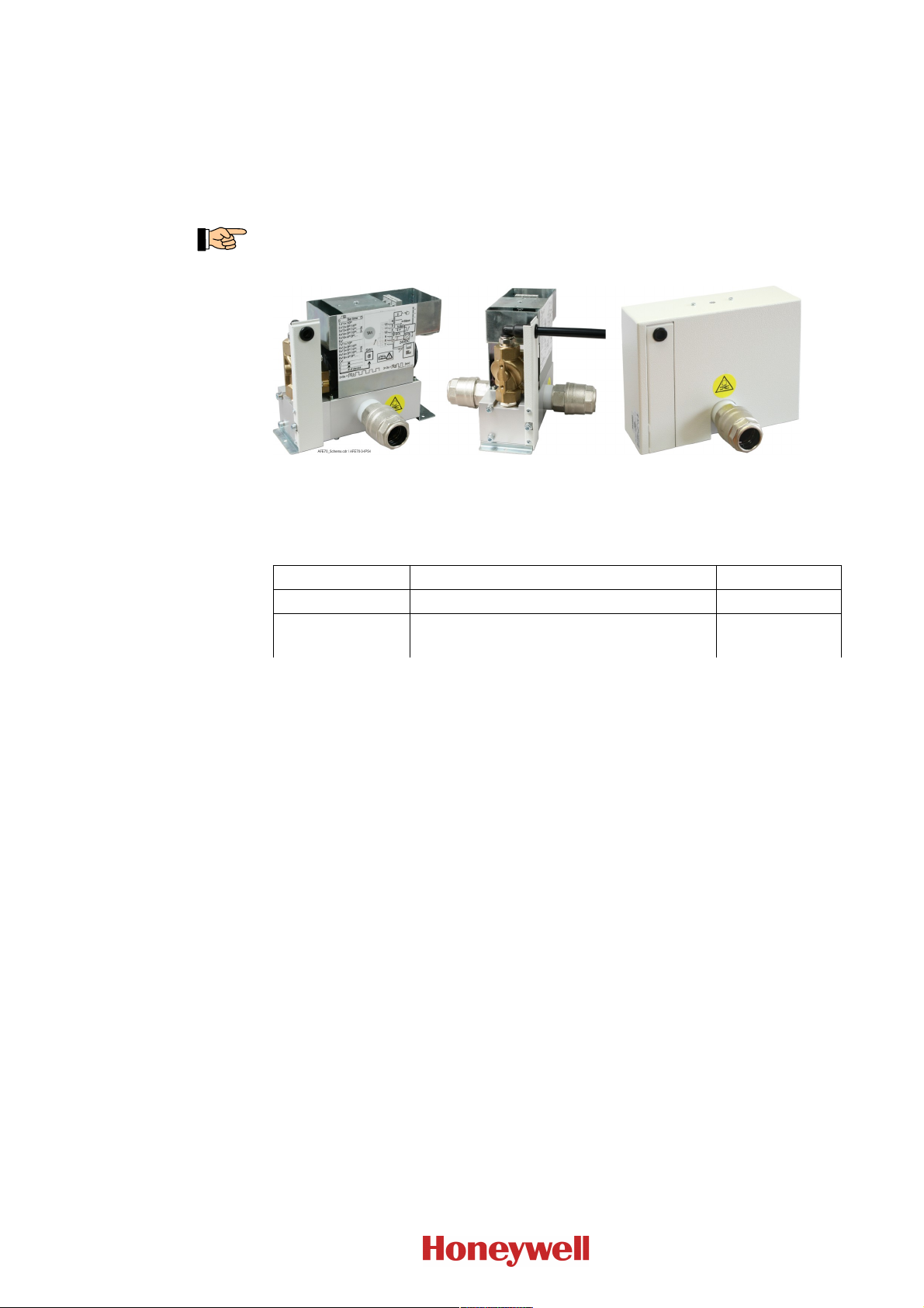
Fig. 1: View of the Automatic Purging Unit F-BO- AFE70
Left: Automatic Purging Unit F-BO-AFE70-3 without cover
Centre: Automatic Purging Unit F-BO-AFE70-3 view of the solenoid valve
Right: Automatic Purging Unit F-BO-AFE70-3 with cover
7
The following types of the Automatic Purging Units F-BO-AFE70 are available:
Type Name Art. No.
F-BO-AFE70-2 Automatic Purging Unit/3500L/IP54
F-BO-AFE70-3 Automatic Purging
Unit/5000L/DF/IP54
1) IP54 means: protected against dust in harmful quantities, complete protection against contact,
protection against water splashed from all directions
2) DF ... refrigeration area down to -20°C
Table 1: Type code of the Automatic Purging Units Series F-BO- AFE70
1) 2)
1)
F-BO-AFE70-2
F-BO-AFE70-3
The Automatic Purging Units F-BO-AFE70-2 and F-BO-AFE70-3 have outer dimensions and functionality in common, they essentially differ in the built-in solenoid valves which allow different air
flow rates and/or extended operating temperatures. The Automatic Purging Unit F-BO-AFE70-2
with a typical air flow rate of the solenoid valve of approx. 3,500 l/min (ANR) at 0.7MPa (7bar) is
designed both for small as well as for larger pipe systems with a large number of aspiration holes.
Thanks to the solenoid valve's typical air flow rate of approx. 5,000 l/min (ANR) at 0.7MPa (7bar),
the Automatic Purging Unit F-BO-AFE70-3 is suitable for even larger and further-flung pipe systems, and in addition it allows use in environments with low temperatures (down to -20°C). Notes
with regard to dimensioning can be found from page 14 onwards in Chapter 4: „Pneumatic components – dimensioning“. The functions of the Purging units are described starting on page 10 in
Chapter 2: „Manner of operation of a Purging unit“.
The information in this User Manual relates to the firmware release number PL0200_V_1.00 of the
control board. In Fig. 11 the position of the label is indicated where the version of the firmware
used can be read. Devices using firmware with another release number can differ in their function
from the range of functions described in this document.
1.2 Intended use
The Automatic Purging Units F-BO-AFE70 are designed and intended exclusively for purging
pipes of aspirating smoke detectors for fire detection systems in buildings, within the limits
described in this User Manual. Any other use of the devices is expressly not intended and forbidden.
I56-4252-010
D200-104-00
8
Chapter 1 • Introduction User Manual Series F-BO-AFE70
The improper use of the Automatic Purging Unit F-BO-AFE70 can endanger life and health
or lead to damage to property. The manufacturer does not accept any responsibility for
improper use.
1.3 Types of symbols
Especially important sections of text in this User Manual are indicated with symbols. The following symbols are used:
Means DANGER! Ignoring these directions can result in danger to life and health.
Means ATTENTION! Ignoring these tips can result in system malfunctions or damage to prop-
erty.
Means TIP! Here the text contains tips for easier operation.
Means that the country-specific and/or the site-specific requirements of the DEVICE and/or
SYSTEM APPROVALS of the fire detection system must be observed.
1.4 Abbreviations, special terms
In order to improve the readability of this User Manual, the generic terms „Purging unit“ and
„F-BO-AFE70“ are used, and the exact type F-BO-AFE70-2 or F-BO-AFE70-3 is specified only if
it is necessary.
The terms „control board“ and AFS70-1 refer to the built-in electronic control of the Purging unit.
The term „overpressure“ refers to the difference between the static absolute pressure of the com-
pressed air and the static absolute pressure of the ambient air. In colloquial language, this is usually
referred to as „pressure“.
„ANR“ means that the specification applies to standard reference atmosphere (at a pressure of
0.1MPa (1bar), a temperature of 20°C and a relative air humidity of 65%).
In this User Manual, the term „aspirating smoke detector“ (which is also abbreviated as „ASD“)
refers both to
the actual evaluation unit of an ASD
as well as sometimes also to
the combination of the essential components of which an ASD consists, namely, the evaluation
unit, the ASD, the sampling pipe system and sometimes the compressed-air supply, etc.
In the context it is always clear what is meant in the particular case.
The fire detection control panel is also abbreviated as „FDCP“.
„PLC“ is the abbreviation for programmable logic controller.
Further abbreviations that are not familiar in everyday usage are avoided in this User Manual.
1.5 Important tips
Fire detection systems and their components must always be planned, installed and put into operation by specialists who are trained on a continuous basis. The specific specialist training on the
functions of the aspirating smoke detectors must be provided by the respective manufacturer or by
persons expressly authorized by the manufacturer for this purpose. Since the Purging unit will be
integrated directly into the pipe system of the ASD, the guidelines of the manufacturer of the ASD,
with regard to the construction and length of the pipe system, must be observed.
The devices that are used in addition to the ASD, such as the fire detection control panel, the power
supply, etc., are only mentioned as examples in this User Manual. The present manual does not
provide any information concerning the expert planning or design of a fire detection system. It
replaces neither the installer's required technical qualification nor his or her specific training.
I56-4252-010
D200-104-00
User Manual Series F-BO-AFE70 Chapter 1 • Introduction
Pay attention to the danger notices given on page 3.
Beware of static charges! The electronic components used in the Automatic Purging Units
F-BO-AFE70 can be destroyed by static charges when the device is open. Before and during the
work being performed on printed circuit boards, static charges from your body must be reliably
discharged by touching an earthed piece of metal.
1.6 Scope of delivery
The Automatic Purging Units F-BO-AFE70 are assembled at the factory and supplied 100% function-tested. Only the pipe connecting parts have been enclosed for reasons of safe transport and still
have to be installed. Please check the delivery for completeness and transport damage before
assembling the equipment.
The delivery scope of the Automatic Purging Unit F-BO-AFE70 includes:
the valve block (with flange-mounted solenoid valve) that has been mounted on the bottom
plate and has been completely assembled and tested, including the mounted control board
AFS70-1, with protection cover (i.e., the housing) and cover.
two 25mm push-in fittings for the connection to the sampling pipe
two pipe nipples G3/4“×34mm
two plastic gaskets Ø32mm×10mm
this User Manual
an end-of-line resistor 5.6kOhm (for the line-monitoring of the fault output of the evaluation
unit of the aspirating smoke detector)
mounting material (three screws and three 6mm plugs for wall mounting)
three cable ties
transport packaging.
9
The Purging unit weighs approx. 3.2kg – the sturdy transport packaging has been designed to
avoid transport damage to any part. If the packaging has been damaged, you must inspect the
Purging unit especially thoroughly.
I56-4252-010
D200-104-00
10
Chapter 2 • Manner of operation of a Purging unit User Manual Series F-BO-AFE70
2 Manner of operation of a Purging unit
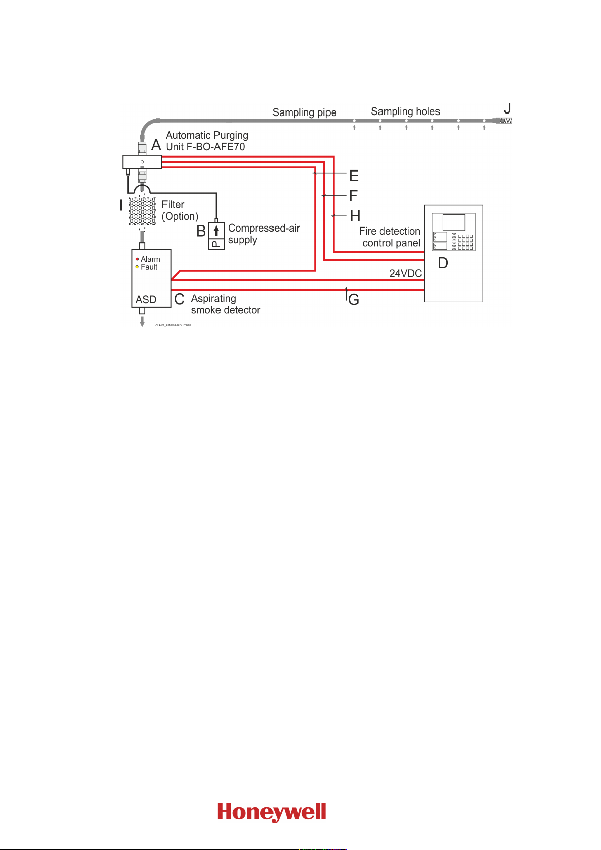
Typical structure of a system, consisting of fire detection control panel, aspirating smoke detector,
Purging unit, compressed-air supply and sampling pipe.
Fig. 2: Depiction of the structure of a system with an Automatic Purging Unit F-BO- AFE70 as well as
2.1 General
Aspirating smoke detectors use a low negative pressure to continuously sample air through aspiration holes of a sampling pipe that is laid in a room or building, and direct the air samples to a central measuring element (the evaluation unit) in order to examine the sample for various characteristics (e.g., the smoke concentration).
the required components and connections
A … Automatic Purging Unit F-BO- AFE70
B … Compressed-air supply
C … Aspirating smoke detector; in the above diagram an ASD with one pipe is shown, note that
for each pipe system a separate Purging unit is needed.
D … Fire detection control panel
E … Power supply line. Both the Purging unit as well as the ASD must be supplied with 24VDC.
F … Transmission of the fault message of the ASD to the fire detection control panel
G … Transmission of the fire alarm of the ASD to the fire detection control panel. The connection
can be established – as shown in the figure above – by means of a conventional line or via
loop modules.
H … The fire detection control panel actuates or activates the F-BO- AFE70
I … Air filter (optional), which can be located before the Purging unit. As a result, on the one
hand the Purging unit is protected against contamination, and on the other hand every Pur-
ging process also cleans the filter. If this is not possible (for example, because the filter case
is not pressure-resistant), the filter must be located between the Purging unit and the aspir-
ating smoke detector.
J … Check valve
Over the operating time, continuously aspirating the ambient medium through the relatively small
aspiration holes and a pipe network with a relatively small cross-sectional area leads to an accumulation of contaminations which can change the aspirated air flow and can even result in the measurement failing completely. In order to prevent this contamination, dirty pipe networks and filter
systems should be regularly cleaned („purged“) by means of compressed air.
For this purpose, clean compressed air is manually or automatically led into the pipe network
and/or the filter system at intervals. In order to protect the evaluation unit of the aspirating smoke
detector against damage caused by exposure to compressed air, in conventional Purging units first a
valve isolates the evaluation unit from the pipe network, and then compressed air is led into the
pipe network through a second valve that is connected to a T-piece.
I56-4252-010
D200-104-00

User Manual Series F-BO-AFE70 Chapter 2 • Manner of operation of a Purging unit
2.2 Characteristic features of the Automatic Purging Unit F-BO-AFE70
In contrast to the structure of conventional Purging units, the Automatic Purging Unit F-BO-AFE70
only needs one (built-in) solenoid valve; furthermore, thanks to its thoughtful design, the Automatic Purging Unit F-BO-AFE70 ensures completely unhindered air flow from the sampling pipe
through the Purging unit to the evaluation unit of the ASD. The unit is controlled by an integrated
control board which has been developed for this special task and which replaces the PLC that is
normally used.
Thanks to the use of high-quality materials and the high-precision processing, the Automatic Purging Unit F-BO-AFE70 is designed to ensure flawless operation for many years.
The trouble-free operation can be affected by various environmental influences, such as temperature, humidity and air that is polluted by gases and aerosols, which can cause increased need for
maintenance and reduce the life span due to wear and tear or contamination.
The following features distinguish the Automatic Purging Unit F-BO-AFE70:
6 Purging programs, each with short or long Purging cycle
they can be manually controlled by means of an external push-button
internal clock for up to 6 daily timed, preventive Purging processes
automatic start if fault message is received from aspirating smoke detector
remote-controlled start (e.g., based on external calendar of factory or office hours)
if there are several F-BO-AFE70's, a time delay can be used so as not to stress the com-
pressed-air system
master-slave mode with actuation of one or more „slaves“
monitoring of the supply voltage
they can be used in a wide pressure range, F-BO-AFE70-2 up to 0.7MPa (7bar) and
F-BO-AFE70-3 up to 1.0MPa (10bar)
they are prepared for connection to all usual fire detection control panels, either via conven-
tional lines or via loop modules.
11
I56-4252-010
D200-104-00
YYY
Y
12
Chapter 3 • Displaying of the operating conditions and operation User Manual Series F-BO-AFE70
3 Displaying of the operating conditions and operation
This chapter describes how the individual operating conditions of the Purging unit are indicated
and explains the respective operational features.
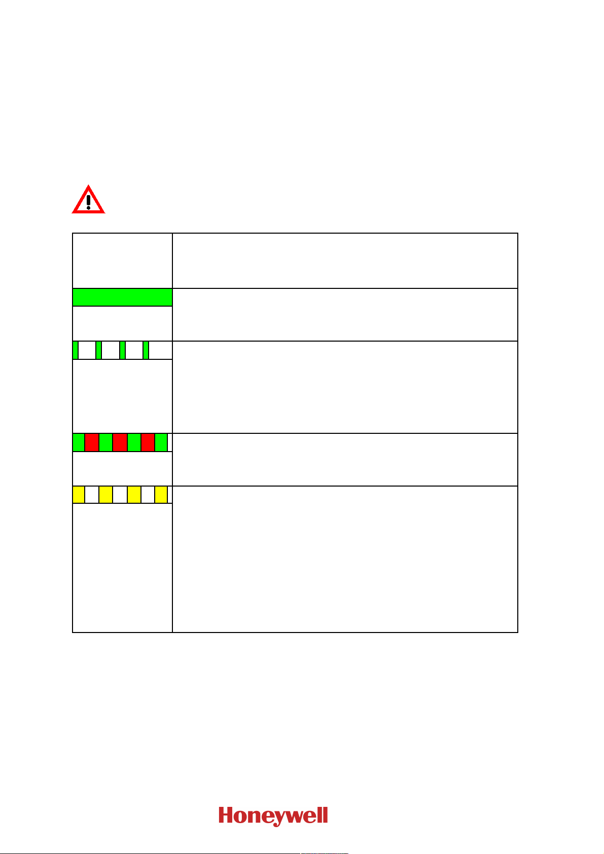
3.1 Operating conditions indicated by the status LED
The control board of the Purging unit continuously checks the status and indicates it in red, yellow
and green, by means of the status LED (see Fig. 5 on page 21).
The conditions that are indicated by the status LED are explained below in Table 2.
If the status LED is dark it is very likely that the Purging unit experiences a power failure or, if it
has been proven that the supply voltage is available, the componentry itself experiences a fault.
In any case you must assume that the Purging unit is inoperable. The fault must be removed as
soon as possible.
Condition of the
status LED
G = green, R = red
Y = yellow
G Condition: Normal condition
illuminates green
Condition of the control board / response time / effect / removal
Response time: Immediately
Effect: Componentry is in normal operation
Removal: Not necessary
↑=G flashing green
G R G R G R G
alternately green and
red
blinking yellow
Condition: No valid Purging program selected
Response time: Immediately
Effect: The componentry is all right, however it will not carry out an automatic
Purging process.
HINT: Switch position 0 allows you to set the time, switch position F allows you to
set the device number.
Removal: Select a valid Purging program.
Condition: The solenoid valve has been activated.
Response time: Immediately
Effect: The Purging process is currently running.
Removal: Not necessary
Condition: Either the aspirating smoke detector reports a fault, or a wire breakage
on the connection line from the Purging unit (terminals 3 and 4) to the aspirating
smoke detector has been detected.
Response time: Immediately
Effect: If the aspirating smoke detector reports a fault, the selected Purging process
will be started.
The aspirating smoke detector could be partly or completely out of order and therefore must be checked.
If the connection line is broken, this will be evaluated like a fault message from the
aspirating smoke detector.
Removal: If there is no fault of the aspirating smoke detector, the connection line
must be checked for freedom from faults.
I56-4252-010
D200-104-00
User Manual Series F-BO-AFE70 Chapter 3 • Displaying of the operating conditions and operation
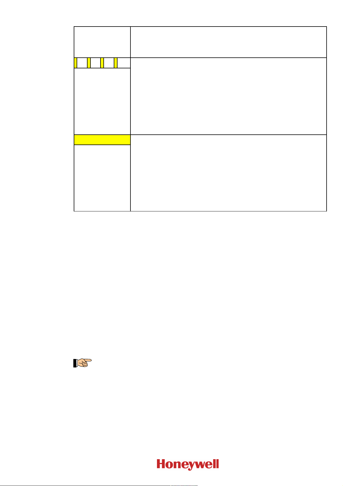
Condition of the
status LED
G = green, R = red
Y = yellow
flashing yellow
Y Condition: There is a fault.
illuminates yellow
Condition of the control board / response time / effect / removal
Condition: A short circuit on the connection line to the fault contact of the aspirat-
ing smoke detector has been detected.
Response time: Immediately
Effect: If the Purging unit is synchronised by an external timer and the short circuit
exists for approx. 60 seconds, the internal clock will be synchronised to 00:00.
If the short circuit exists for less than 50 seconds, this will be indicated by the
status LED, but apart from that it will not be evaluated. If the short circuit exists
for more than 70 seconds, this will be evaluated as fault, the condition of the status
LED will change to illuminating yellow.
Removal: If the time has not been synchronised, the connection line must be
checked.
Response time: Immediately
Effect: Maybe the aspirating smoke detector is partly or completely out of order
and must be checked.
Removal: If an air flow fault of the aspirating smoke detector exists, further
manual Purging processes should be carried out in order to remove the clogging
(see on page 31 in Chapter 9.3: „Location of the display and operating elements
and terminals on the control board of the Automatic Purging Unit F-BO-AFE70“).
If there is another fault, it must be removed on the aspirating smoke detector.
If there is no fault of the aspirating smoke detector, the connection line must be
checked for freedom from faults.
13
Table 2: Possible conditions of the componentry status display
3.2 Operation by the user
If a valid Purging program has been set on the Purging unit, the unit operates in the automatic mode
and the status LED indicates the current condition.
In this case the Purging processes will be carried out automatically. If additional Purging processes
are needed, you can carry them out by pressing the external push-button „Manual activation“,
provided that this feature has been prepared by the installer of the system. In this case, the compressed air will be blown into the pipe network for as long as the push-button is being pressed, but
the maximum duration for one press of the push-button is limited to 2 minutes.
3.3 Operation by the installer
If a valid Purging program (Purging program „1“ … „C“) has been set on the Purging unit, additional Purging processes can be started manually.
A manual Purging process can be started by briefly pressing the button TA1; depending on the Purging program that has been set with the rotary switch „Purging program“ SW1, this will carry out a
long or short Purging process.
The button TA1 will only be accessible after removing the cover (see Fig. 4 on page 20).
I56-4252-010
D200-104-00
2.00 3.15 4.00 12.57 6.00 28.28
2.10 3.47 4.10 13.21 6.10 29.23
2.20 3.81 4.20 13.86 6.20 30.20
2.30 4.16 4.30 14.53 6.30 31.18
2.40 4.53 4.40 15.21 6.40 32.17
2.50 4.91 4.50 15.91 6.50 33.19
2.60 5.31 4.60 16.62 6.60 34.22
2.70 5.73 4.70 17.35 6.70 35.26
2.80 6.16 4.80 18.10 6.80 36.32
2.90 6.61 4.90 18.86 6.90 37.40
3.00 7.07 5.00 19.64 7.00 38.49
3.10 7.55 5.10 20.43 7.10 39.60
3.20 8.05 5.20 21.24 7.20 40.72
3.30 8.56 5.30 22.07 7.30 41.86
3.40 9.08 5.40 22.91 7.40 43.01
3.50 9.63 5.50 23.76 7.50 44.18
3.60 10.18 5.60 24.64 7.60 45.37
3.70 10.76 5.70 25.52 7.70 46.57
3.80 11.35 5.80 26.43 7.80 47.79
3.90 11.95 5.90 27.34 7.90 49.02
Diameter
[mm]
Area
[mm²]
Diameter
[mm]
Area
[mm²]
Diameter
[mm]
Area
[mm²]
14
Chapter 4 • Pneumatic components – dimensioning User Manual Series F-BO-AFE70
4 Pneumatic components – dimensioning
4.1 Purging unit
The geometry of the sampling pipe and the number and size of the aspiration holes depends on the
size and geometry of the room as well as the technical possibilities of the aspirating smoke detector
used. Thanks to the special construction of the Automatic Purging Unit F-BO-AFE70, it does not
cause an additional air resistance in the piping that is worth mentioning, and therefore it does not
have to be taken into consideration when dimensioning the pipe system.
Through intensive tests and experiments, the recommended values for dimensioning that are stated
below, have been established. Please note that the specified values are only approximate values
because a huge number of components (the length and the geometry of the pipe, the position of the
aspiration holes along the piping, the opening pressure of a check valve that may exist, etc.) affect
the Purging process. Therefore you can only make sure that the Purging unit is working properly by
carrying out a final test on the individual system.
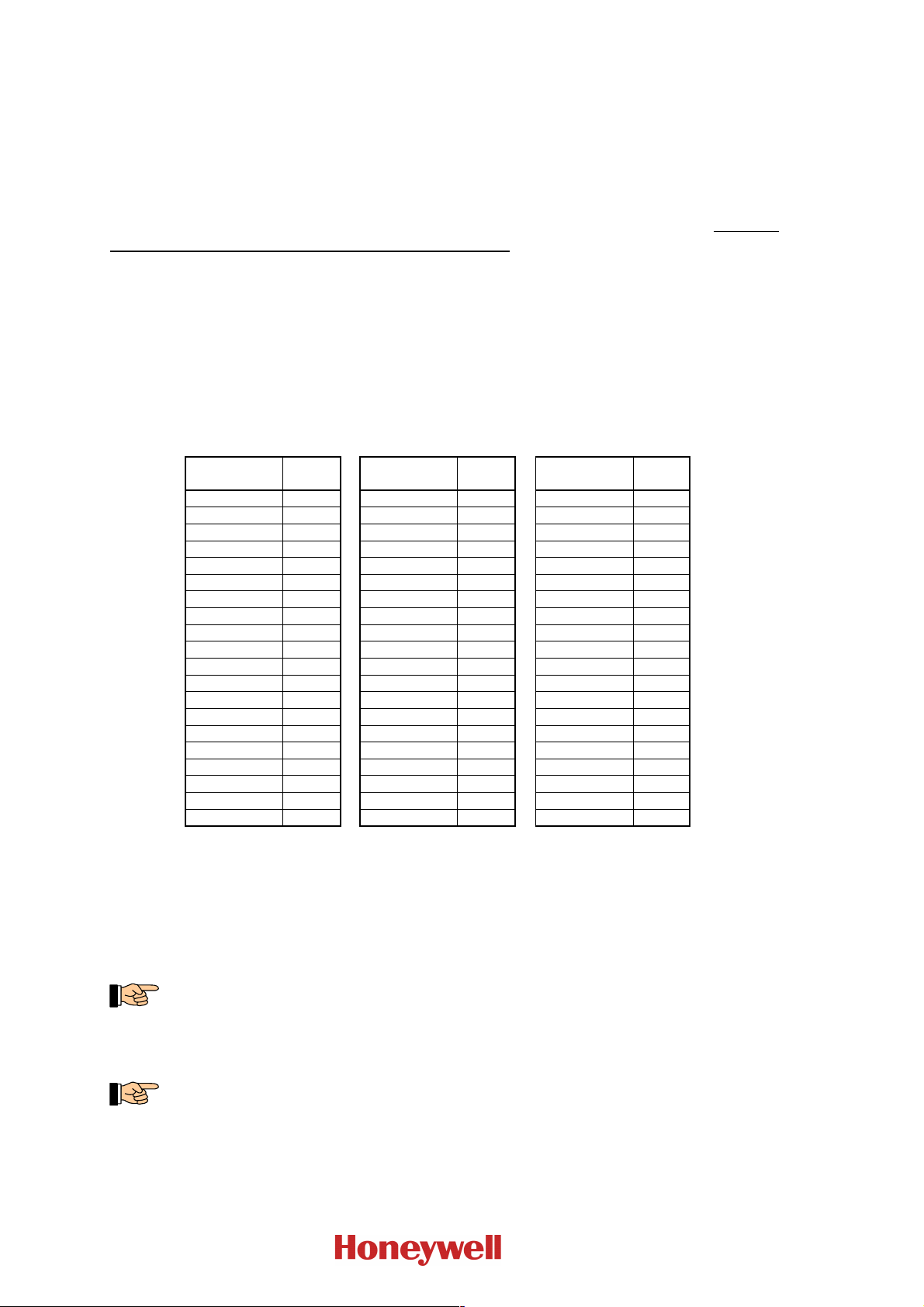
First calculate the total aperture area of the aspiration holes that exist in the pipe network. In order
to keep the calculation simple, the table below shows the area of a circular hole, depending on its
diameter.
Table 3: Calculation aid for the determination of the total aperture area of the aspiration holes in the
sampling pipework; add up the stated values for the holes in the piping that is to be connected to
the Purging unit. The diameters that have been marked in bold in the table are the predetermined
standard values for the Series FAAST and VESDA.
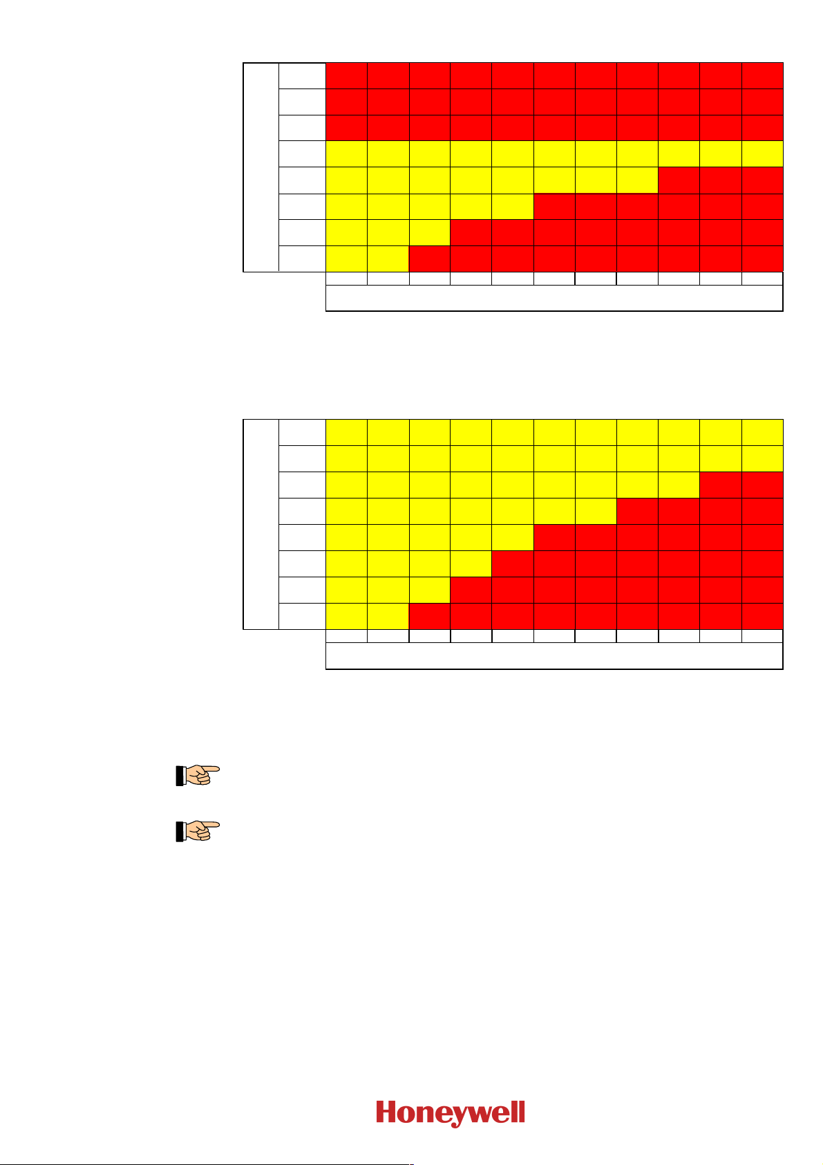
The tables below show the operation limits of the Automatic Purging Units F-BO-AFE70-2 and
F-BO-AFE70-3, depending on the input overpressure during the Purging process and on the sum of
the aperture area of the aspiration holes of the piping that is connected to the Purging unit.
The data is based on a DN25 pipe network that has been realised as straight branch, and on a
check valve with an opening pressure of 25kPa (0.25bar) that has been installed at the end of the
pipe network. A safety factor has been added to the data and therefore it can be regarded as
approximate value for normal system configurations, but the proper functioning of the respective
system must always be verified in a test!
During the Purging process, the input overpressure decreases, depending on the quality of the
compressed-air supply and the air volume that is consumed. The input overpressure value listed
in the table is the value when air is being consumed, i.e., the decreased value!
I56-4252-010
D200-104-00
User Manual Series F-BO-AFE70 Chapter 4 • Pneumatic components – dimensioning
- - - - - - - - - - -
- - - - - - - - - - -
- - - - - - - - - - -
- - -
- - - - - -
- - - - - - - -
- - - - - - - - -
40mm² 60mm² 80mm² 100mm² 120mm² 140mm² 160mm² 180mm² 200mm² 220mm² 240mm²
Eingangsüberdruck
input overpressure
1.00MPa
(10bar)
0.90MPa
(9bar)
0.80MPa
(8bar)
0.70MPa
(7bar)
AFE70-2
(3500L)
AFE70-2
(3500L)
AFE70-2
(3500L)
AFE70-2
(3500L)
AFE70-2
(3500L)
AFE70-2
(3500L)
AFE70-2
(3500L)
AFE70-2
(3500L)
AFE70-2
(3500L)
AFE70-2
(3500L)
AFE70-2
(3500L)
0.60MPa
(6bar)
AFE70-2
(3500L)
AFE70-2
(3500L)
AFE70-2
(3500L)
AFE70-2
(3500L)
AFE70-2
(3500L)
AFE70-2
(3500L)
AFE70-2
(3500L)
AFE70-2
(3500L)
0.50MPa
(5bar)
AFE70-2
(3500L)
AFE70-2
(3500L)
AFE70-2
(3500L)
AFE70-2
(3500L)
AFE70-2
(3500L)
0.40MPa
(4bar)
AFE70-2
(3500L)
AFE70-2
(3500L)
AFE70-2
(3500L)
0.30MPa
(3bar)
AFE70-2
(3500L)
AFE70-2
(3500L)
gesamte Öffnungsfläche
total aperture area
- -
- - - -
- - - - - -
- - - - - - -
- - - - - - - -
- - - - - - - - -
60mm² 90mm² 120mm² 150mm² 180mm² 210mm² 240mm² 270mm² 300mm² 330mm² 360mm²
Eingangsüberdruck
input overpressure
1.00MPa
(10bar)
AFE70-3
(5000L)
AFE70-3
(5000L)
AFE70-3
(5000L)
AFE70-3
(5000L)
AFE70-3
(5000L)
AFE70-3
(5000L)
AFE70-3
(5000L)
AFE70-3
(5000L)
AFE70-3
(5000L)
AFE70-3
(5000L)
AFE70-3
(5000L)
0.90MPa
(9bar)
AFE70-3
(5000L)
AFE70-3
(5000L)
AFE70-3
(5000L)
AFE70-3
(5000L)
AFE70-3
(5000L)
AFE70-3
(5000L)
AFE70-3
(5000L)
AFE70-3
(5000L)
AFE70-3
(5000L)
AFE70-3
(5000L)
AFE70-3
(5000L)
0.80MPa
(8bar)
AFE70-3
(5000L)
AFE70-3
(5000L)
AFE70-3
(5000L)
AFE70-3
(5000L)
AFE70-3
(5000L)
AFE70-3
(5000L)
AFE70-3
(5000L)
AFE70-3
(5000L)
AFE70-3
(5000L)
0.70MPa
(7bar)
AFE70-3
(5000L)
AFE70-3
(5000L)
AFE70-3
(5000L)
AFE70-3
(5000L)
AFE70-3
(5000L)
AFE70-3
(5000L)
AFE70-3
(5000L)
0.60MPa
(6bar)
AFE70-3
(5000L)
AFE70-3
(5000L)
AFE70-3
(5000L)
AFE70-3
(5000L)
AFE70-3
(5000L)
0.50MPa
(5bar)
AFE70-3
(5000L)
AFE70-3
(5000L)
AFE70-3
(5000L)
AFE70-3
(5000L)
0.40MPa
(4bar)
AFE70-3
(5000L)
AFE70-3
(5000L)
AFE70-3
(5000L)
0.30MPa
(3bar)
AFE70-3
(5000L)
AFE70-3
(5000L)
gesamte Öffnungsfläche
total aperture area
Table 4: Operation limits of the Automatic Purging Unit F-BO- AFE70-2, depending on the input pres-
sure that is available during the Purging process („input overpressure“) and the sum of the aperture areas of the piping that is to be connected to the Purging unit („total aperture area“). The
Automatic Purging Unit F-BO-AFE70-2 must not be operated with input overpressures of more
than 0.7MPa (7bar)!
15
Table 5: Operation limits of the Automatic Purging Unit F-BO- AFE70-3, depending on the input pres-
sure that is available during the Purging process („input overpressure“) and the sum of the aperture areas of the piping that is to be connected to the Purging unit („total aperture area“). The
Automatic Purging Unit F-BO-AFE70-3 must not be operated with input overpressures of more
than 1.0MPa (10bar)!
The Automatic Purging Unit F-BO-AFE70 still works perfectly at and below an input overpressure of 0.1MPa (1bar), but perhaps the resulting pressure built up in the pipe network will not
suffice to open the check valve and to clean the pipe network completely.
If the sum of the area of the aspiration holes of the piping exceeds the specified values, branches
can also be purged, by means of the master-slave mode (see from page 34 onwards in Chapter
9.4.2: „Connection of Purging units in the master-slave mode with direct actuation through the
fire detection control panel (in accordance with EN 54-13)“), through separate Automatic Purging Units F-BO-AFE70. This also applies analogously to the areas marked with „-“ in the
Tables 4 and 5.
4.2 Compressed-air supply
I56-4252-010
D200-104-00
The required size of the air vessel as well as the air delivery volume of the compressed-air supply
essentially depend on the following factors:
positive operating pressure of the compressed-air supply (air vessel overpressure)
chosen input overpressure of the Purging unit
total opening time of the solenoid valve during the Purging process.
 Loading...