

Page 1
208414, 208415 Replacement
Power Supply Kit for Electronic Air Cleaner
INSTALLATION INSTRUCTIONS
APPLICA TION
These kits replace the power supplies with W8600E solidstate performance indicators (SSPI) used in the F50F and
F58F Electronic Air Cleaners. See Table 1.
NOTE: The W8600E Remote Performance Indicator
driver circuit board has been calibrated with the
power supply in this kit. False wash indications
will occur if used with a different power supply.
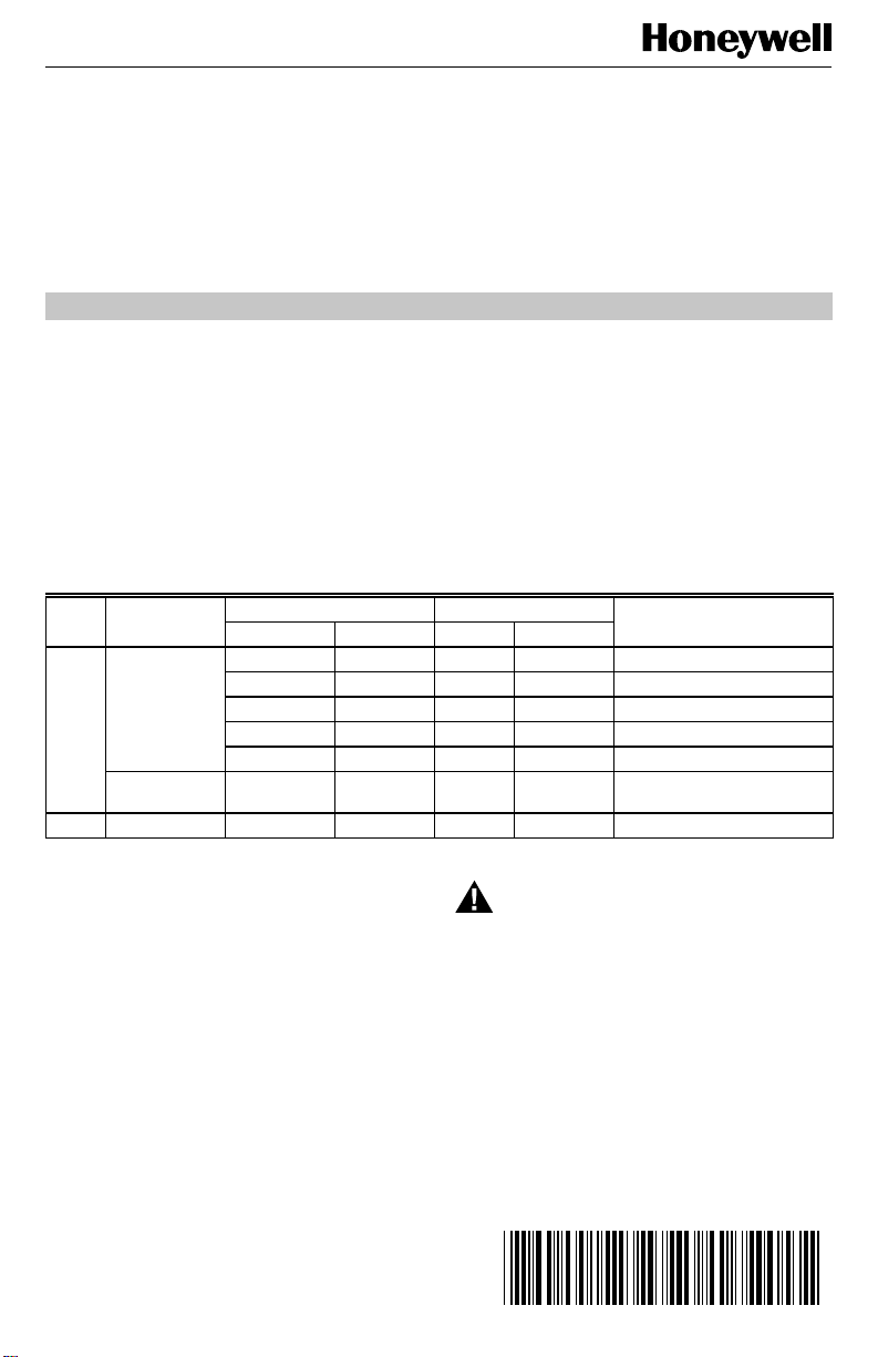
Table 1. Power Supply Replacement Guide.
EAC Electrical
Model Rating
F50F 120 Vac, 60 Hz 16 x 20 406 x 508 1.33 N/A 208414G
220/240 Vac,
50/60 Hz
F58F 120 Vac, 60 Hz 20 x 25 508 x 635 2.10 3 208414H
Nominal Size Ionizer Current
(in.) (mm) (mA) J6 Position
16 x 25 406 x 635 1.65 2 208414H
20 x 20 508 x 508 1.65 2 208414H
20 x 25 508 x 635 2.10 3 208414H
20 x 12-1/2 508 x 318 1.05 N/A 208414C
20 x 12-1/2 508 x 318 1.05 N/A 208415C
NOTE: Use the 120 Vac replacement power supply in
Table 1 when servicing the F50F or F58F
Electronic Air Cleaners that were modified with
the 203365A Transformer Kit to operate at 220/
240 Vac.
The power supply board in the 208414H Kit has been
calibrated to provide a selectable ionizer current output.
Select the correct ionizer current by moving the J6 shorting
bar to the correct position. See Tables 1 and 2. See Fig. 8
for location of J6. All other kits have single-current output.
Replacement Power Supply
(OS No.)
INST ALLATION
When Installing this Product…
1. Read these instructions carefully. Failure to follow
them could damage the product or cause a hazardous condition such as electrical shock.
2. Check the ratings given in the instructions and on
the product to make sure the product is suitable for
your application.
3. Installer must be a trained, experienced service
technician.
4. After installation is complete, check out product
operation as provided in these instructions.
®U.S. Registered Trademark
Copyright © 1999 Honeywell Inc. • All Rights Reserved
W ARNING
ELECTRICAL HAZARD.
Can Cause Electrical Shock or Equipment
Damage.
Disconnect power before removing old power
supply board and installing replacement power
supply board.
T o Remove Old Power Supply Board
NOTE: Observe the location of leadwires to be replaced
on the power supply. Label the leadwires to
identify them for reconnecting later.
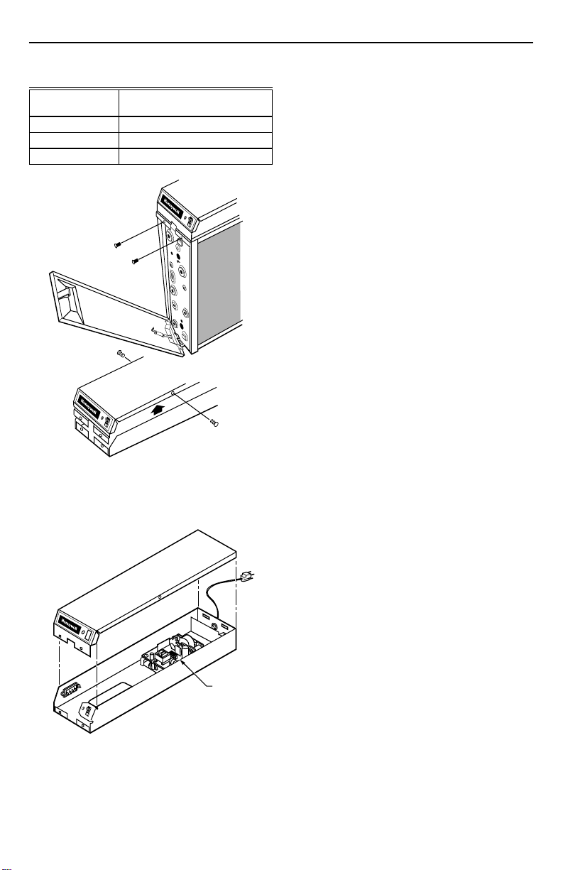
■ Open access door. See Fig. 1.
■ Open power box.
X-XX UL
69-1136-2
Page 2
208414, 208415 REPLACEMENT POWER SUPPLY KIT FOR ELECTRONIC AIR CLEANER
Table 2. Ionizer Current Output Guide
J6 Shorting Bar
Position Ionizer Current Output (mA)
32.10
21.65
11.05
REMOVING COVER
FROM POWER BOX.
2
1
3
M5676A
Fig. 1. Remove cover from power box.
■ Disconnect the leads from 1, 2, 3, 4, P1, P2, P3, P4,
P5, P12, P14, P17, P18 and P21 on the old power
supply. See Fig. 2 through 5.
POWER
SUPPLY
M5764
Fig. 2. Power supply location on F50F and F58F.
■ Remove and discard W8600E terminal block and
wiring. Set aside screws for later use.
■ Remove and set aside the sheetmetal screws holding
the board in place.
■ Discard the old power supply.
Install New Power Supply
■ When replacing the power supply, reuse the remain-
ing leadwires in the air cleaner when removing the old
power supply.
■ Install W8600E terminal block and wiring supplied
with this kit using screws previously removed.
■ Align the mounting holes and mount the new power
supply in the air cleaner, using the sheetmetal screws
removed earlier. Orient the power supply so P1 and
P2 are toward the front (closest to the switch and
neon light).
■ Route the remaining leads so the P3 and P4 leads
are separate from the low voltage leads. Route all
high voltage leads around, rather than over, the power
supply board. Low voltage leads can go over the
power supply board.
■ Connect leads to the terminals on the new power supply.
IMPORTANT
Do not splice ionizer and collector leads. These
leads must be unbroken to avoid electrical shock
through the connector or tape covering the splice.
■ Plug the electronic air cleaner directly into the correct
voltage and frequency outlet or reconnect power for
directly wired devices. See Fig. 3 or 4 for internal
schematic. The air cleaner operates correctly at any
fan speed on a multispeed or modulated speed
system wired with conduit or plugged in.
NOTE: To reduce the risk of electric shock, this product
has a grounding type plug with a third (grounding) pin. This plug fits only into a grounding type
power outlet. If the plug does not fit into the
outlet, contact a qualified electrician to install the
proper outlet. Do
not
change the plug in any way.
CHECKOUT
IMPORTANT
The following instructions are for use only by
qualified personnel.
With all components in place, turn on the air cleaner switch
and energize the system blower. Check the following
points of operation:
1. The neon light next to the on-off switch is on. If a
W8600E is part of the installation, check the wall
panel and make sure the ON LED is lighted. The
W8600E CHECK LED comes on if there is a
problem with the high voltage power supply.
2. Turn off the system blower. The neon light should go
off after a few seconds. The neon light shows that
the air cleaner is energized and the high voltage
power supply is working properly.
3. Turn on the system blower. With the air cleaner
energized, push the test button. A snapping sound
indicates that the collector voltage is present on the
cell. The W8600E CHECK LED comes on when the
test button is held down.
4. With a multispeed blower, repeat steps 1 through 3
for each fan speed.
5. If operation is not as described, refer to the Troubleshooting and Service section.
69-1136—2
2
Page 3
208414, 208415 REPLACEMENT POWER SUPPLY KIT FOR ELECTRONIC AIR CLEANER
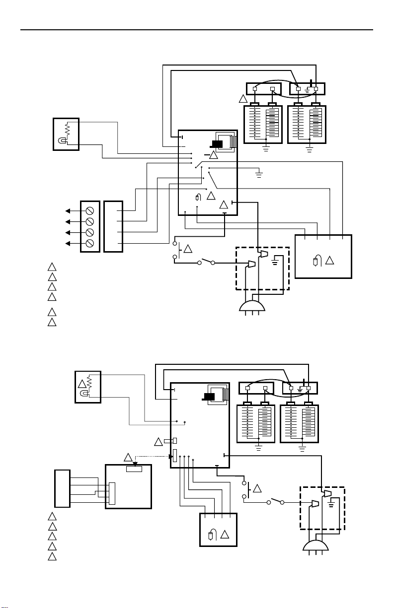
INTERNAL SCHEMATIC FOR ELECTRONIC AIR CLEANER WITH W8600E.
BLACK
BLACK
TERMINAL STRIP
FRONT BACK
1
1
TO
W8600E
WALL
PANEL
1 INTERLOCK SWITCH.
2 OUTPUT REDUCTION JUMPER.
3 AIRFLOW SWITCH DISABLE JUMPER.
4 RESISTOR FOR W8600 WASH INDICATION THRESHOLD. PRESENT ON POWER
SUPPLIES MANUFACTURED WITH DATE CODE 9430 AND EARLIER.
5 ONE-CELL UNIT SIMILAR, BUT WITH JUST ONE CELL.
6 P1, P2 TERMINALS ON 120V MODELS ONLY. POWER CONNECTIONS ON 240V MODELS ARE TO QUICK-CONNECTS ON POWER
SUPPLY TRANSFORMER. BROWN LEAD GOES TO TOP TERMINAL AND BLACK LEAD TO BOTTOM TERMINAL.
2
2
3
3
4
4
P3
P4
P21
P17
BLACK
1
BLACK
P5
P12
2
P18
BLACK COLLECTOR
POWER
SUPPLY
J2
2
J7
4
P14
3
1
4
R43
BLACK
6
P2
P1
RED IONIZER
5
GREEN
BROWN
BLACK
WHITE
RED
VIOLET
BLACK
TEST
BUTTON
BLACK
ORANGE
GRAY
GREEN
AIRFLOW SWITCH BOARD
W4 W2 W1 W3
Fig. 3. Internal schematic for F50F and F58F Electronic Air Cleaner with W8600E.
CONTACT
BOARD
3
M15096
BLACK COLLECTOR
BLACK
5
BLACK
2
4
BLUE
B4
RED
YELLOW
GREEN
5
3
2
1
R3
Y2
G1
1 INTERLOCK SWITCH.
2 SHORTING BAR.
3 AIRFLOW SWITCH DISABLE JUMPER.
4 W8600E REMOTE PERFORMANCE INDICIATOR DRIVER.
5 NEON LIGHT.
J1
J2
P3
P4
E5
E4 E3
J1
E6
J5
BLACK
E2
GRAY
VIOLET
E1
ORANGE
AIRFLOW SWITCH BOARD
POWER
SUPPLY
P2
P1
BLACK
W4 W2 W1 W3
3
RED IONIZER
BROWN
BLACK
RED
BLACK
1
BLACK
Fig. 4. Retrofitted schematic for F50F and F58F Electronic Air Cleaner with W8600E.
3
TEST
BUTTON
BLACK
CONTACT
BOARD
WHITE
GREEN
M15097
69-1136—2
Page 4

208414, 208415 REPLACEMENT POWER SUPPLY KIT FOR ELECTRONIC AIR CLEANER
BLACK
7
BLACK
4
BLUE
B4
RED
YELLOW
GREEN
5
3
2
1
R3
Y2
G1
1 INTERLOCK SWITCH.
2 SHORTING BAR.
3 AIRFLOW SWITCH DISABLE JUMPER.
4 W8600E REMOTE PERFORMANCE INDICIATOR DRIVER.
5 TOP TERMINAL ON TRANSFORMER
6 INPUT POWER. PROVIDE DISCONNECT MEANS AND OVERLOAD PROTECTION AS REQUIRED.
7 NEON LIGHT.
J1
J2
P3
P4
E5
2
J1
Fig. 5. Retrofitted schematic for 220/240 Vac F50F Electronic Air Cleaner with W8600E.
TROUBLESHOOTING AND SERVICE
W ARNING
ELECTRIC SHOCK HAZARD.
Can Cause Personal Injury or Equipment
Damage. Instructions are Only for Use by
Qualified Personnel.
The following procedures expose hazardous live
parts. Disconnect from power between checks and
proceed carefully.
Tools and Equipment
Troubleshooting the electronic air cleaner requires:
• Needle-nose pliers for stringing ionizer wires and
inserting edge connectors.
• Test meter.
Although a meter is needed for some steps, the primary
diagnostic tools are the
See Fig. 6.
neon light
and the
test button
.
BLACK COLLECTOR
RED IONIZER
E6
J5
E4 E3
BLACK
E2
VIOLET
5
BROWN
E1
ORANGE
GRAY
W4 W2 W1 W3
AIRFLOW SWITCH BOARD
Test Button
When pushed, the
to ground. The resulting arcing sound indicates that high
voltage is being supplied to the collector. The solid state
power supply controls current flow to the collector. On air
cleaners with a W8600E, the CHECK LED comes on
when the
BLACK
1
BLACK
3
test button
test button
TEST
BUTTON
RED
BLACK
BLACK
BLACK
L1 L2
shorts from collector voltage
is held down.
COLLECTOR
TERMINAL
IONIZER
TERMINAL
COLLECTOR
TERMINAL
CONTACT
BOARD
6
220/240V
50/60 Hz
WHITE
GREEN
M15098
Neon Light (On Power Box)
The neon light is powered through the power supply and is
on when the power supply output voltage is normal.
69-1136—2
M6155
Fig. 6. Use an ohmmeter to check
the electronic cells for short circuits.
4
Page 5

208414, 208415 REPLACEMENT POWER SUPPLY KIT FOR ELECTRONIC AIR CLEANER
Check Led (Air Cleaners With W8600E)
The CHECK LED on the W8600E lights to indicate the
following problems: excessive dirt loading (beyond that
required to activate the WASH LED), partial shorting of
the collector, continuous ionizer or collector arcing,
power supply failure, excessive ionizer current, or any
condition causing a major reduction in high voltage.
Power Supply
W ARNING
ELECTRIC SHOCK HAZARD.
Can Cause Personal Injury.
Always turn off power and remove access door
before removing the power box or its cover.
The solid state power supply assembly has no field
serviceable components. If troubleshooting indicates a
power supply or solid state performance indicator problem,
replace the entire power supply assembly.
Troubleshooting Procedure
The electronic air cleaner Troubleshooting chart shows
how to quickly isolate an air cleaner problem. The primary
diagnostic tools are the
Some steps require a meter. See Fig. 7.
TROUBLESHOOTING AIR CLEANERS WITH SOLID STATE PERFORMANCE INDICATOR.
START
MAKE SURE ELECTRONIC
CELL(S) ARE CLEAN, DRY
AND PROPERLY INSTALLED.
MAKE SURE PREFILTER(S)
ARE IN CABINET SLOT
FARTHEST FROM FURNACE.
TURN ON ELECTRONIC AIR
CLEANER AND SYSTEM
FAN.
CHECK NEON LIGHT.
CORRECT
WIRING.
WIRING
CHECK WIRING BETWEEN
W8600E AND AIR CLEANER.
USE MAX NO. 18 4-WIRE
THERMOSTAT CABLE
CONNECTED 1(G) TO 1(G),
2(Y) TO 2(Y), 3(R) TO 3(R),
AND 4(B) TO 4(B).
1
2
3
NOT OK
WIRING OK
REPLACE
3
W8600E.
FOR POWER SUPPLY REPLACEMENT, SEE FORM 69-0776.
W8600E HAS THREE LIGHT-EMITTING DIODES (LEDS):
ON, WASH, AND CHECK.
W8600E OPERATION CAN BE CHECKED SEPARATELY.
SEE W8600E INSTRUCTIONS.
PUSH TEST BUTTON AND
LISTEN FOR SNAPPING
SOUND.
OFF
CHECK ON LED IN
W8600E
OFF
DEPRESS AND HOLD DOWN
TEST BUTTON. CHECK
LED IN W8600E
SHOULD COME ON
TURN OFF AIR CLEANER
AND REMOVE CELL(S)
ONLY (NOT PREFILTERS).
CLOSE ACCESS DOOR
AND TURN ON AIR CLEANER.
WASH LED IN W8600E
SHOULD COME ON.
OFF
ELECTRONIC AIR CLEANER
AND W8600E ARE OK.
ON
ON
ON
YES
2
ON
2
2
TO USE THIS CHART:
1.
FOLLOW THE STEPS IN ORDER; DO NOT SKIP AROUND.
2.
EACH TIME YOU ISOLATE AND FIX A PROBLEM, GO BACK TO START.
3.
REPEAT ALL THE STEPS UNTIL THE AIR CLEANER CHECKS OUT OK.
THESE SERVICING INSTRUCTIONS ARE FOR USE BY QUALIFIED PERSONNEL
ONLY. TO REDUCE RISK OF ELECTRIC SHOCK, DO NOT PERFORM ANY
SERVICING OTHER THAN CONTAINED IN THE OPERATING INSTRUCTIONS
UNLESS YOU ARE QUALIFIED TO DO SO.
PUSH TEST BUTTON
OFF
AND LISTEN FOR
SNAPPING SOUND.
NO
NO
TURN OFF AIR CLEANER
AND REMOVE CELL(S)
ONLY (NOT PREFILTERS).
CLOSE ACCESS DOOR
AND TURN ON
AIR CLEANER.
CHECK NEON LIGHT.
INSPECT CELL(S) FOR:
BENT COLLECTOR
•
PLATES
BROKEN IONIZER
•
WIRES
DIRT ON INSULATORS
•
DAMAGED IONIZER
•
OR COLLECTOR
CONTACT TABS
YES
REPAIR OR
REPLACE
CELL(S).
WITH OHMMETER,
CHECK FOR SHORT
BETWEEN:
••CELL FRAME AND
IONIZER SECTION
CELL FRAME AND
COLLECTOR SECTION
CELL
SHORTED
REPLACE
CELL.
Fig. 7. Troubleshooting air cleaners with solid-state performance indicator.
ON
CELL OK.
WARNING
RISK OF ELECTRIC SHOCK
YES
OFF
CHECK FOR CORRECT INPUT
VOLTAGE ACROSS P1 AND P2
TERMINALS ON POWER SUPPLY.
TURN OFF AIR CLEANER,
REPLACE CELLS(S) AND
DISCONNECT FOUR W8600E
LEADS AT AIR CLEANER.
REPLACE ACCESS DOOR.
NO
TURN ON AIR CLEANER. PUSH
TEST BUTTON AND LISTEN
FOR SNAPPING SOUND.
REPLACE
POWER
BOX OR
POWER SUPPLY.
INFINITE
RESISTANCE
AIR CLEANER OK. TURN OFF
AIR CLEANER AND RECONNECT
W8600E LEADS 1(G) TO 1(G),
2(Y) TO 2(Y), 3(R) TO 3(R), AND
4(B) TO 4(B).
neon light
REPLACE LIGHT ASSEMBLY.
FIX
WIRING.
and the
WARNING
THIS STEP EXPOSES
DANGEROUSLY HIGH
VOLTAGE. ONLY A
QUALIFIED SERVICE
TECHNICIAN SHOULD
ATTEMPT THIS STEP.
NO
YES
NO
YES
1
test button
M5609E
.
5
69-1136—2
Page 6

208414, 208415 REPLACEMENT POWER SUPPLY KIT FOR ELECTRONIC AIR CLEANER
Modification To Reduce Ozone Odor
W ARNING
ELECTRIC SHOCK HAZARD.
Can Cause Personal Injury
Always disconnect power before opening power
supply cover.
The electronic air cleaner generates a small amount of
ozone in normal operation. During the first or second week
of operation, the amount may be higher because of sharp
edges on some of the new high voltage metal parts.
Normal use quickly dulls these edges.
The average person can detect the odor of ozone in
concentrations as low as 0.003 to 0.010 parts per million
(ppm). The electronic air cleaner contributes 0.005 to
0.010 ppm of ozone to the indoor air. The U.S. Food and
Drug Administration and Health and Welfare Canada
recommend that indoor ozone concentration does not
exceed 0.050 ppm. As a comparison, the
level in major cities is sometimes as high as 0.100 ppm.
However, if desired, the ozone generated by the air
cleaner can be reduced in one of two ways:
1. Install an activated carbon filter downstream from
the air cleaner. Make sure particles from the air filter
cannot fall into the air cleaner.
W ARNING
ELECTRIC SHOCK HAZARD.
Can Cause Personal Injury.
Only a trained service technician should perform
the following procedure.
outdoor
ozone
2. To reduce ozone production about 20 to 25 percent
and reduce efficiency about seven to ten percent,
depending on actual airflow delivered by the furnace
blower:
a. Unplug or disconnect power supply to the air
cleaner.
b. Open the access door.
c. Remove the power box cover. See Fig. 1.
d. Locate J5 shorting bar on the power supply.
See Fig. 8. Remove the shorting bar and
reinstall on only one pin.
NOTE: The ozone will be reduced, and the
shorting bar is available for reinstallation, if
needed.
e. Replace the power supply cover and access
door. Turn on the power.
f. Repeat the checkout procedure before leaving
the job.
J4 SHUNT
IN POSITION
TO DISABLE
NEON LIGHT
OUTPUT
J4
P3
J4 SHUNT
IN POSITION
TO ENABLE
NEON LIGHT
OUTPUT
J5 SHUNT
IN NORMAL
POSITION
J5 SHUNT
IN OZONE
REDUCED
POSITION
P4
J4
E5
E6
J4
3 2 1
J6
J5
J5
E4 E3
J5
Fig. 8. Move J5 shorting bar to reduce ozone
production about 20 to 25 percent.
E2
E1
J3
J1
P1
P2
M14200
69-1136—2
6
Page 7

208414, 208415 REPLACEMENT POWER SUPPLY KIT FOR ELECTRONIC AIR CLEANER
LIMITED TWO-YEAR WARRANTY
Honeywell warrants this product to be free from defects in the workmanship or materials, under normal use and service,
for a period of two (2) years from the date of purchase by the consumer. If, at any time during the warranty period, the
product is defective or malfunctions, Honeywell shall repair or replace it (at Honeywell’s option) within a reasonable period
of time.
If the product(s) is defective, please contact:
a) the dealer from whom you purchased it, or
b) the local Honeywell Authorized Repair Station, or
c) the local Honeywell Home and Building Control Office, or
d) the Honeywell Customer Assistance Center toll free at 1-800-468-1502, or
e) package the defective cell, power supply or other component with care, along with a bill of sale, receipt, or other
dated proof of purchase, and a short description of the malfunction, and ship it, prepaid, to the following address:
Honeywell, Inc.
Return Goods Department
1050 Berkshire Lane
Plymouth, MN 55441-4437
This warranty does not cover removal or reinstallation costs. This warranty shall not apply if it is shown by Honeywell that
the defect or malfunction was caused by damage that occurred while the product was in the possession of a consumer.
Honeywell sole responsibility shall be to repair or replace the product within the terms stated above. HONEYWELL SHALL
NOT BE LIABLE FOR ANY LOSS OR DAMAGE OF ANY KIND, INCLUDING ANY INCIDENTAL OR CONSEQUENTIAL
DAMAGES RESULTING, DIRECTLY OR INDIRECTLY, FROM ANY BREACH OF ANY WARRANTY, EXPRESS OR
IMPLIED, OR ANY OTHER FAILURE OF THIS PRODUCT. Some states do not allow the exclusion or limitation of
incidental or consequential damages, so this limitation may not apply to you.
THE WARRANTIES SET FORTH HEREIN ARE EXCLUSIVE, AND HONEYWELL EXPRESSLY DISCLAIMS ALL
OTHER WARRANTIES, WHETHER WRITTEN, ORAL, IMPLIED OR STATUTORY, INCLUDING BUT NOT LIMITED TO
ANY WARRANTIES OF MERCHANTABILITY, WORKMANSHIP, OR FITNESS FOR A PARTICULAR PURPOSE.
This warranty gives you specific legal rights, and you may have other rights which vary from state to state.
If you have any questions concerning this warranty, please write our Customer Assistance Center, Honeywell Inc.,
P.O. Box 524, MN27-2164, Minneapolis, Minnesota 55440-0524 or call toll-free at 1-800-468-1502, Monday-Friday,
7:00 a.m.-5:30 p.m. Central time. In Canada, Honeywell Limited/Honeywell Limitee, 155 Gordon Baker Road, North
York, Ontario M2H 3N7.
7
69-1136—2
Page 8

208414, 208415 REPLACEMENT POWER SUPPLY KIT FOR ELECTRONIC AIR CLEANER
Home and Building Control
Honeywell Inc.
Honeywell Plaza
P.O. Box 524
Minneapolis, MN 55408-0524
69-1136—2
69-1136—2 G.H. Rev. 12-99 Printed in Mexico
Home and Building Control
Honeywell Limited-Honeywell Limitée
155 Gordon Baker Road
North York, Ontario
M2H 3N7
8
 Loading...