

Page 1
F150E
whole-house air quality system
F150E
W8600A
AIRWATCH™
Media Air Cleaner
PRODUCT DATA
FEATURES
• W8600A AIRWATCH™ filter change indicator.
• High efficiency media filter captures particles as small
as 0.3 micron.
• Efficiency ratings based on the American Society of
Heating, Refrigerating and Air Conditioning Engineers
Standard 52.2-1999.
• Applicable to all gas, oil, and electric forced warm air
furnaces and to compressor cooling up to 5 tons.
• Mounts in the return air duct.
• Cabinet can support weight of residential furnace and
evaporator coil.
• Requires no electrical connections.
• Mounts in any position.
• Requires no maintenance except periodic media filter
replacement.
• Quick and easy media filter replacement.
• Later upgrade to higher performing Honeywell media
or electronic air cleaner is easy.
APPLICATION
The F150E Media Air Cleaner captures a significant amount
of the airborne particles from the air circulated through the
unit.
® U.S. Registered Trademark
© 2004 Honeywell International Inc.
All Rights Reserved
Contents
Application.........................................................................1
Features ............................................................................1
Specifications ....................................................................2
Ordering Information .........................................................2
Planning the Installation ....................................................3
Installation ........................................................................6
Checkout ...........................................................................7
68-0245EF-3
Page 2

F150E MEDIA AIR CLEANER
SPECIFICATIONS
IMPORTANT
The specifications in this publication do not include
normal manufacturing tolerances; therefore, an
individual unit may not exactly match the listed
specifications. This product is tested and calibrated
under closely controlled conditions, and some minor
differences in performance can be expected if those
conditions are changed.
Model:
F150E Media Air Cleaner includes cabinet, access door and
pleated media filter, and W8600A AirWatch™ Indicator.
Application:
Use with gas, oil, and electric forced warm air furnaces and
with compressor cooling. Can be used with heat pumps if
filter is changed regularly to prevent excessive pressure
drop. Not recommended for applications where pressure
drop may be critical.
Pressure Drop:
Initial pressure drop at 492 fpm: 0.23 in. wc.
Dust fed to 0.5 in. wc pressure drop: 72 grams.
Efficiency:
Efficiency Ratings: Based on American Society of Heating,
Refrigerating and Air-Conditioning Engineers Standard
52.2-1999.
Minimum Efficiency Reporting Valve (MERV): 10 at 492 fpm.
Filter Media:
Pleated for greater media capacity.
Capacity And Pressure Drop:
See Fig 2.
Initial Pressure Drop: 0.23 in. wc at 492 fpm.
Temperature Rating:
-40° to +140°F (-40° to +60°C).
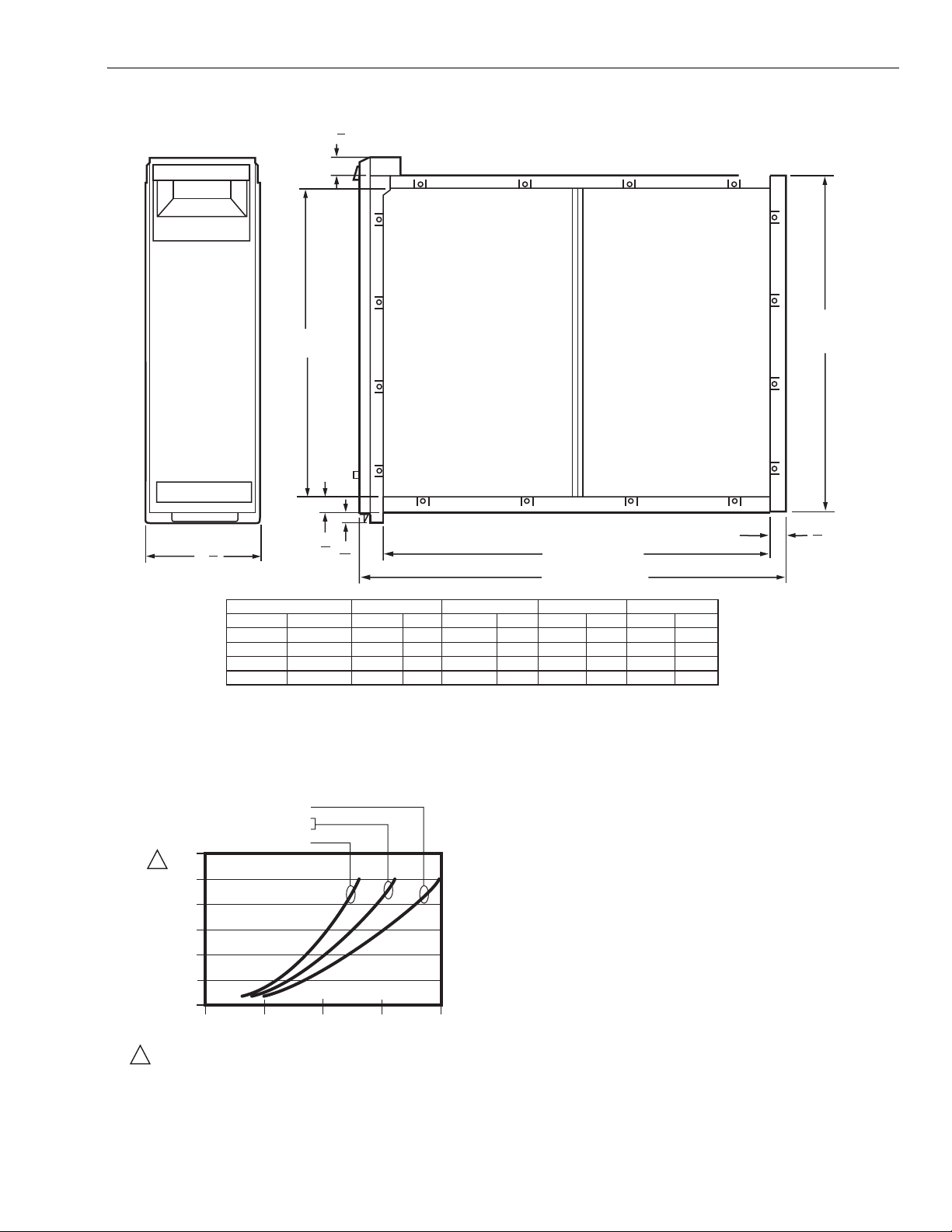
Dimensions:
See Fig. 1.
Mounting:
Mounts in any position in the return air duct, usually next to
the furnace blower compartment. Cabinet is sturdy enough
to support weight of a residential furnace and evaporator
coil.Underwriters Laboratories, Inc.:
Listed to UL 900, Class 2.
Included Accessory:
W8600A AirWatch™ Indicator.
Upgrade Path:
The F150E uses the same cabinet as the F300E Electronic
Air Cleaner. Upgrade may require installing the cell key,
electronic cells, protective screens and installation and
wiring of the power box, depending on model.
Initial Efficiency*:
Replacement Media:
For optimum system performance, replace the filter every six
INITIAL EFFICIENCY* :
85.1%
61.8%
24.8%
% EFFICIENCY
0.3 - 1.01.0 - 3.03.0 - 10.0
% EFFICIENCY
*LMS Technologies Inc. Fractional Efficiency Testing FC100, 2004.
months (before heating season and before cooling
season). Adjust the schedule to you needs, but replace the
filter at least annually.
Filter Size (in.) Part Number
16 x 25 FC100A1029
16 x 20 FC100A1003
20 x 25 FC100A1037
20 x 20 FC100A1011
ORDERING INFORMATION
When purchasing replacement and modernization products from your TRADELINE® wholesaler or distributor, refer to the
TRADELINE® Catalog or price sheets for complete ordering number.
If you have additional questions, need further information, or would like to comment on our products or services, please write or
phone:
1. Your local Honeywell Automation and Control Products Sales Office (check white pages of your phone directory).
2. Honeywell Customer Care
1885 Douglas Drive North
Minneapolis, Minnesota 55422-4386
In Canada—Honeywell Limited/Honeywell Limitée, 35 Dynamic Drive, Scarborough, Ontario M1V 4Z9.
International Sales and Service Offices in all principal cities of the world. Manufacturing in Australia, Canada, Finland, France,
Germany, Japan, Mexico, Netherlands, Spain, Taiwan, United Kingdom, U.S.A.
68-0245EF-3 2
Page 3
F150E MEDIA AIR CLEANER
1
(29)
1
8
6
(172)
DIM. A
(SEE TABLE)
7
3
4
F150E SIZE
IN.
16 X 25
20 X 25
16 X 20
20 X 20
8
(22)
MM
406 X 635
508 X 635
406 X 508
508 X 508
5
8
(16)
DIM. A
IN. MM IN. MM
14-7/16
18-7/16
14-7/16
18-7/16
367
468
367
468
16-3/16
20-3/16
16-3/16
20-3/16
DIM. B
DIM. C (SEE TABLE)
DIM. D (SEE TABLE)
411
23-1/4
513
23-1/4
411
18-1/4
513
18-1/4
DIM. C
IN. MM IN.
591
25-1/2
591
25-1/2
457
20-1/2
457
20-1/2
DIM. D
MM
648
648
521
521
DIM. B
(SEE TABLE)
7
8
(22)
M22578
Fig. 1. Installation dimensions in in. (mm) of air cleaner.
FILTER SIZE
20 X 25
16 X 25
20 X 20
0.300
1
0.250
0.200
0.150
0.100
0.050
PRESSURE DROP (IN. WC)
0.000
0
WHEN FIRST INSTALLED. PRESSURE DROP INCREASES AS FILTER
1
BECOMES LOADED. REPLACE FILTER WHEN PRESSURE DROP
REACHES 0.5 IN. WC. (0.1 kPa).
16 X 20
500 1000 1500
AIRFLOW (CFM)
Fig. 2. Capacity, Pressure Drop and Area of
F150E Filter Media.
PLANNING THE INSTALLATION
Location
The media air cleaner should be installed where all the air
passing through the system is circulated through it. The best
location is in the return air duct next to the blower compartment so the media air cleaner can help to keep the blower
motor and evaporator coils clean. Do not mount in the supply
air duct.
For most efficient air cleaning, spread airflow evenly across
the face of the media. If the duct is a different size than the
media air filter cabinet, gradual transitions are required. If the
duct turns sharply just before the air filter, turning vanes are
2000
M14709A
required.
Choose a location that is readily accessible for checking and
replacing the filter. Allow at least 26 in. (660 mm) clearance in
front of the unit for removal of the cartridge.
Install the media air filter where the temperature will not
exceed the ratings in the Specifications.
3 68-0245EF-3
Page 4

F150E MEDIA AIR CLEANER
A
Applications With Air Conditioning
Mount the media air cleaner upstream of the evaporator coil in
a cooling system. The filter will help to keep the coil clean and
reduce maintenance.
Applications With A Humidifier
The media air cleaner is compatible with humidifiers. Avoid
applications where water mist will reach the media. If an
atomizing humidifier is used, the filter media will require
replacement more often because of minerals in the water.
Choose Mounting Position
The media air cleaner can be mounted in any position, but the
arrow on the cartridge must point in the same direction as the
airflow. See Figs. 3-10 for proper location of the media air
cleaner for a variety of furnace installations. Note that the
media air cleaner cabinet is sturdy enough to easily support
the weight of the furnace and evaporator coil. See Fig. 4.
M940
Fig. 4. Highboy furnace, with installation beneath furnace.
Media air cleaner is mounted horizontally where return
enters from below.
M939A
Fig. 3. Highboy furnace, with side installation.
Media air filter is mounted vertically where return
enters side inlet of furnace.
68-0245EF-3 4
M941A
Fig. 5. Highboy furnace, with closet installation. Media air
cleaner is mounted vertically on furnace between furnace
and louvered return air opening in closet door.
Page 5

M942A
F150E MEDIA AIR CLEANER
Fig. 6. Lowboy furnace, with media air cleaner mounted
horizontally in return plenum just above furnace and
opposite heating plenum.
M944A
Fig. 8. Central fan installation, with media air cleaner
mounted horizontally in central return duct.
M945A
Fig. 9. Horizontal furnace, with media air filter mounted
vertically in return duct near furnace.
M943A
Fig. 7. Counterflow furnace, with media air cleaner
mounted horizontally in return duct or plenum just
above furnace.
M946A
Fig. 10. Two or more media air cleaners used in a high
capacity system.
5 68-0245EF-3
Page 6

F150E MEDIA AIR CLEANER
Determining Sheetmetal Requirements
The media air cleaner is adaptable to all new or existing
forced air heating and cooling systems used in residential
applications. Transitions or turning vanes may be required in
some applications for effective media air cleaner operation.
Transitions
Transitions are needed when the duct is a different size than
the media air cleaner cabinet. When fabricating:
1. Use gradual transitions to reduce air turbulence and
increase efficiency. See Fig. 11.
2. Use no more than 20 degrees (about 4 in. per running ft.
(100 mm per 300 linear mm) of expansion on each side
of a transition fitting.
Turning Vanes
If the media air cleaner is installed next to an elbow or angle
fitting, add turning vanes inside the angle to distribute airflow
more evenly across the face of the media. See Fig 12.
Offsets
If the duct connection to the furnace in a side installation
allows less than 7 in. (178 mm) for mounting media air cleaner
cabinet, attach an offset to the elbow. See Fig. 13.
DUCT SIZE CHANGED GRADUALLY TO PREVENT TURBULENCE.
20 DEGREE EXPANSION PER SIDE PER
FITTING (4 IN. PER RUNNING FOOT
[100 MM PER 300 LINEAR MM])
RETURN AIR
DUCT
LESS
THAN
7 in.
(178 mm)
1 REQUIRED TURNING VANES HELP DISTRIBUTE AIRFLOW EVENLY.
OFFSET
AT LEAST
7 in.
1
(178 mm)
M948A
Fig. 13. Typical use of duct offset to make room for
media air cleaner.
INSTALLATION
When Installing this Product…
1. Read these instructions carefully. Failure to follow them
could damage the media air filter or cause a hazardous
condition.
2. Check the ratings given in the instructions and on the
media air cleaner to make sure the product is suitable
for your application.
3. Installer must be a trained, experienced service technician.
TRANSITION FITTING
MEDIA AIR CLEANER CABINET
M947B
Fig. 11. Duct size changed gradually to prevent
turbulence.
TURNING
VANES
M5651
Fig. 12. Turning vanes installed in bend help distribute
airflow evenly over face of media.
68-0245EF-3 6
Remove Furnace Filter And Clean Blower Compartment
Before starting the installation, remove and discard the
existing furnace filter (if used). Thoroughly clean the blower
compartment. If possible, power vacuum the ductwork to
remove accumulated dust in an occupied home or remove
construction dirt in a new home. The media air cleaner cannot
remove dirt that has settled in the blower compartment and
distribution ducts.
Install The Cabinet
The following procedure describes a typical side installation
on an existing highboy furnace. Alternate procedures are
noted as appropriate. Other changes in installation
procedures may be necessary to complete your installation.
Review The Installation Plan
Temporarily place the cabinet on the floor, oriented as it will be
when installed. Insert and remove the cartridge to make sure
the plan allows adequate clearance for easy removal and
replacement of the cartridge.
Make sure that shop-fabricated sheetmetal components, such
as turning vanes, are available.
Page 7

F150E MEDIA AIR CLEANER
Fasten The Cabinet To The Furnace
Align the cabinet with the return air opening. Place blocks
under the cabinet, as necessary, to make sure the unit sits
securely. Create an opening in the furnace to match the
cabinet opening. Attach the cabinet securely to the furnace.
Attach the unit directly or fit a starting collar in the furnace
opening. Either drill holes and fasten with sheetmetal screws
or rivets, or use slip joints. If you are drilling holes, use a
locking pliers to help hold the unit in place during drilling.
Install Turning Vanes
Install turning vanes to help distribute air equally over the full
surface of the upstream side of the media. Install them
whenever an abrupt 90 degree elbow is installed directly
against the media air cleaner cabinet.
Fasten Cabinet To Ductwork
Fasten side of cabinet to the ductwork using sheet-metal
screws, rivets, or slip joints, as appropriate.
Connect Ductwork
Connect the vertical duct section to the elbow. If the vertical
drop of the duct is less than 7 in. (178 mm) from the side of
the furnace, shorten the horizontal trunk or attach an offset
fitting to the elbow. See Fig. 12. When ductwork is properly
aligned, connect the vertical duct to the horizontal trunk.
Seal Joints
Seal all joints in the return air system between the media air
filter and the furnace to prevent dust from entering the clean
airstream.
Install Filter Cartridge
Slide the filter cartridge into the cabinet, making sure the
arrow on the cartridge points in the direction of air flow.
NOTE: The UV air treatment system and the humidifier set-
tings are set for one year. The air cleaner settings
are selectable according to homeowner activities and
schedule.
Set the air cleaner filter time DIP switches for 3, 6, 9 or 12
months according to the information on the back of the device.
Leave the factory default DIP switch settings to change the
filter every three months. If no air cleaner filter is installed,
move DIP switch 4 and 5 settings to off (left).
Install two AAA alkaline batteries (provided) in the harness on
the back of the device. Observe that the device performs a
self-test, beeping and flashing the LC display individually for
each device (air cleaner, UV air treatment system, humidifier)
installed in the home. Then press and hold the black reset
button on the bottom of the device for five seconds or until the
display stops flashing to start the timers. Observe the battery
LCD: on solidly means that the unit is correctly powered;
flashing indicates that the battery requires replacing.
CHECKOUT
Visually check the installation. Make sure:
• Airflow is in the direction of the arrow on the media air filter
cartridge.
• Turning vanes and transitions, if used, are properly
installed.
• Joints in sheet metal between media fir filter and furnace
are sealed.
• All sheet metal connections are complete.
• Original furnace filter has been removed and blower
compartment is cleaned.
Replace any access doors removed during the Installation or
Checkout.
Run the furnace or cooling system through one complete
cycle to make sure the system operates as desired.
Replace access door. Insert the tab on the bottom of the door
into the slot in the cabinet. Swing the door closed and press it
into place.
Install W8600A AIRWATCH™ Indicator
Mount the W8600A next to the thermostat or any other
convenient location in the living area of the home. The device
is battery-operated so has no electrical requirements.
Remove the device from the base and mark the mounting
holes, using the base as a template. Drill the holes. Position
the base over the holes and install the mounting screws
provided. Tighten the screws until the base is mounted firmly
on the wall. Replace the device onto the base.
Set the DIP switches on the back of the W8600A according to
the equipment installed in the home. Use the default settings
when all devices (air cleaner, UV air treatment system, and
humidifier) are installed. Or move the DIP switch to off (left)
when a device is not installed.
Maintenance
The W8600A beeps every fifteen minutes when an LCD is
flashing. Replace the part in the system that corresponds with
the flashing LCD.
NOTE: When batteries need replacing, replace them within
30 seconds of removal to maintain the correct
indicator time. After 30 seconds of replacing the
batteries, if the LCD is blank, remove and install new
batteries. For other parts, press and hold the black
button on the bottom of the device to reset the timer
after replacing parts.
The media filter must be replaced when pressure drop across
the media filter reaches 0.5 in. w.c. (0.1 kPa). or at least
annually. If the media air cleaner is installed downstream from
an atomizing humidifier or if the installation includes both
heating and cooling, more frequent replacement may be
necessary. Clogged media must be replaced promptly to
avoid restricting airflow and reducing efficiency of the heatingcooling system. Record the replacement date in the space
provided on the replacement media filter.
7 68-0245EF-3
Page 8

F150E MEDIA AIR CLEANER
LCD If arrow is flashing or unit is beeping Reset by ...
Battery Batteries need changing Changing batteries within 30 seconds of removing old batteries
to maintain correct indicator time.
Air Cleaner Media filter needs replacing Pressing and holding reset button for 10 seconds or until arrow
is no longer displayed.
UV Air Treatment UV Lamps need replacing in UV air
treatment system.
Pressing and holding reset button for 10 seconds or until arrow
is no longer displayed.
Humidifier Humidifier pad needs replacing Pressing and holding reset button for 10 seconds or until arrow
is no longer displayed.
Automation and Control Solutions
Honeywell International Inc. Honeywell Limited-Honeywell Limitée
1985 Douglas Drive North 35 Dynamic Drive
Golden Valley, MN 55422 Scarborough, Ontario
68-0245EF-3 G.H. 11-04 www.honeywell.com/yourhome
M1V 4Z9
 Loading...