

Page 1
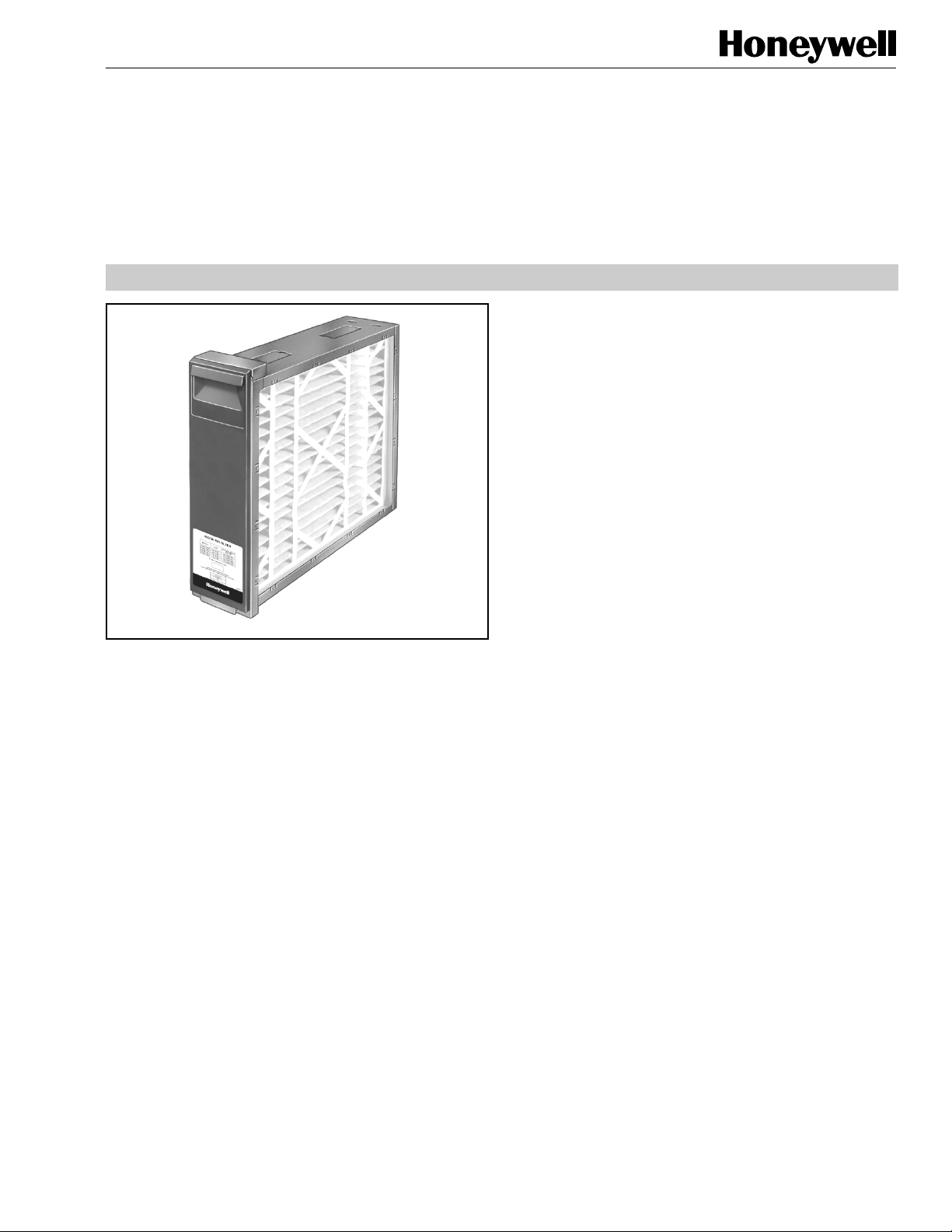
F100
Media Air Cleaner
PRODUCT DATA
FEATURES
• High efficiency media filter (included with some
models) captures particles as small as 0.3 micron.
• FC100A Efficiency and arrestance ratings based on
the American Society of Heating, Refrigerating and Air
Conditioning- Engineers Standard 52.2-1999.
• Applicable to all gas, oil, and electric forced warm air
furnaces and to compressor cooling up to 5 tons.
• Mounts in the return air duct.
• Cabinet can support weight of residential furnace and
evaporator coil.
• Requires no electrical connections.
• Mounts in any position.
APPLICATION
The F100 Media Air Cleaner captures a significant amount of
the air-borne particles from the air circulated through the unit.
SPECIFICATIONS
IMPORTANT
The specifications in this publication do not include
normal manufacturing tolerances; therefore, an
individual unit may not exactly match the listed
specifications. This product is tested and calibrated
under closely controlled conditions, and some minor
differences in performance can be expected if those
conditions are changed.
Models:
F100F Media Air Cleaner includes cabinet, access door and
pleated media filter. Some units include a W8600A
AirWatch™ Indicator. F100B Media Air Cleaner includes
cabinet and access door.
Application:
Use with gas, oil, and electric forced warm air furnaces and
with compressor cooling. Can be used with heat pumps if
filter is changed regularly to prevent excessive pressure drop.
Not recommended for applications where pressure drop may
be critical.
• Requires no maintenance except periodic media filter
replacement.
• Quick and easy media filter replacement.
• Later upgrade to higher performing media or
electronic air cleaner is easy. (Note that 25 x 20 in. and
25 x 22 in. models cannot be upgraded to an electronic
air cleaner.)
FC100A Efficiency:
Efficiency Ratings: Based on American Society of Heating,
Refrigerating and Air-Conditioning Engineers Standard
52.2-1999.
Initial Efficiency: 25 percent (0.3 micron particles).
Minimum Efficiency Reporting Valve (MERV): 10 at 492 fpm.
Filter Media:
Pleated for greater media capacity.
Capacity And Pressure Drop:
See Fig 2.
Initial Pressure Drop: 0.233 in. wc at 492 fpm.
Temperature Rating:
-40° to +140°F (-40° to +60°C).
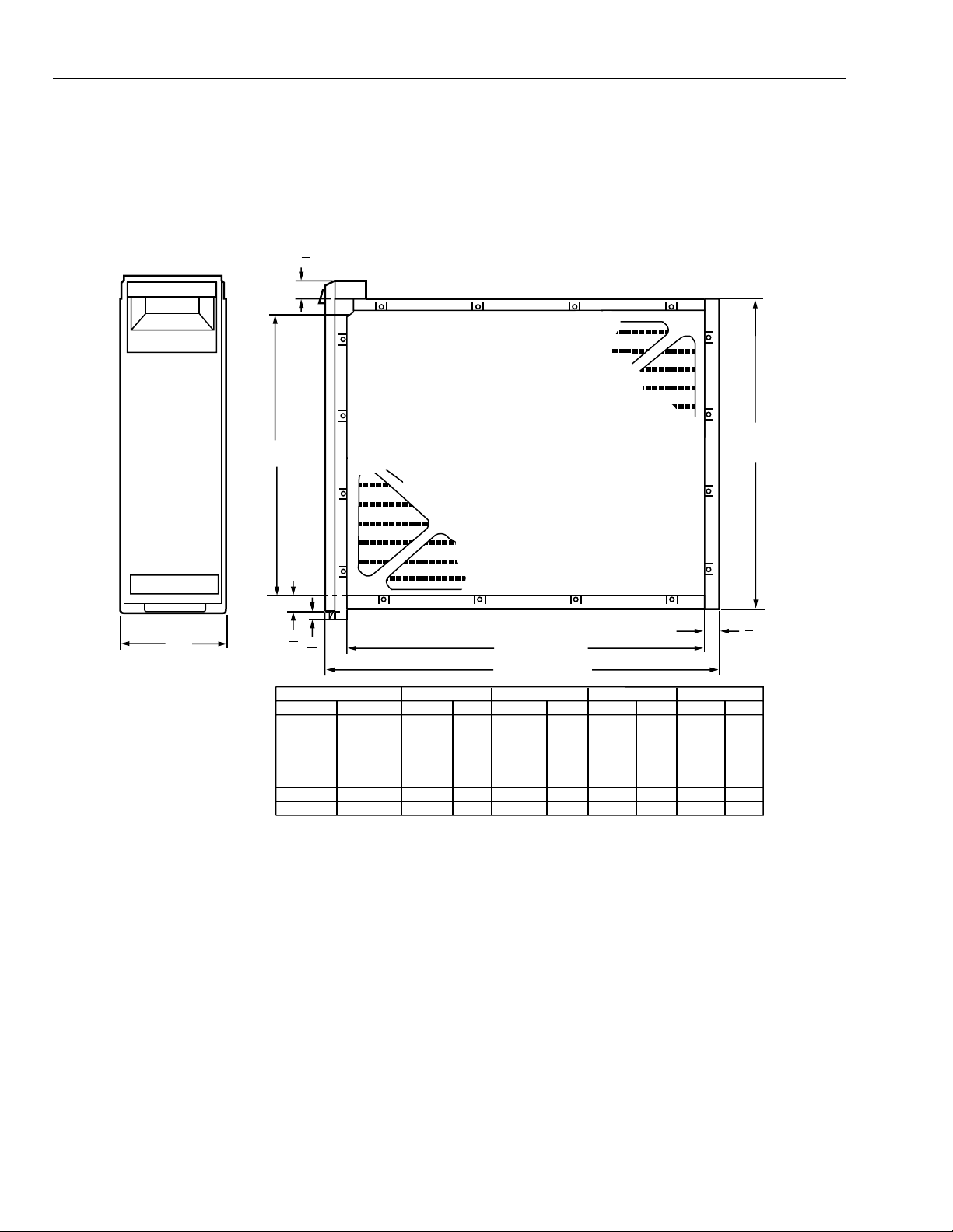
Dimensions:
See Fig. 1.
® U.S. Registered Trademark
Copyright © 2004 Honeywell International Inc. • All Rights Reserved
68-0239EF-4
Page 2
F100 MEDIA AIR CLEANER
Mounting:
Mounts in any position in the return air duct, usually next to
the furnace blower compartment. Cabinet is sturdy enough to
support weight of a residential furnace and evaporator coil.
Approvals:
Underwriters Laboratories, Inc.:
Listed to UL 900, Class 2.
1
(29)
1
8
DIM. A
(SEE TABLE)
Upgrade Path:
The F100 uses the same cabinet as the F50 Electronic Air
Cleaner. Upgrade may require installing the cell key,
electronic cells, protective screens and installation and wiring
of the power box, depending on model. (Note that 25 x 20 in.
and 25 x 22 in. models cannot be upgraded to an electronic
air cleaner.)
Accessory:
W8600A AirWatch™ Indicator (optional with some models).
DIM. B
(SEE TABLE)
DIM. D
7
8
(22)
648
521
648
521
333
524
572
M14710A
6
(171)
3
4
7
5
8
8
(22)
(16)
F100 SIZE
IN.
16 X 25
16 X 20
20 X 25
20 X 20
20 X 12 1/2
25 X 20
25 X 22
MM
406 X 635
406 X 508
508 X 635
508 X 508
508 X 318
635 X 508
635 X 559
DIM. C (SEE TABLE)
DIM. D (SEE TABLE)
DIM. A
IN. MM IN. MM
14 7/16
14 7/16
18 7/16
18 7/16
18 7/16
23 5/16
23 5/16
367
367
468
468
468
592
592
DIM. B
16 3/16
16 3/16
20 3/16
20 3/16
20 3/16
25 1/8
25 1/8
411
411
513
513
513
638
638
DIM. C
IN. MM IN. MM
23 1/4
591
457
591
457
276
467
514
25 1/2
20 1/2
25 1/2
20 1/2
13 1/8
20 5/8
22 1/2
18 1/4
23 1/4
18 1/4
10 7/8
18 3/8
20 1/4
Fig. 1. Installation dimensions in in. (mm) of air cleaner.
ORDERING INFORMATION
When purchasing replacement and modernization products from your TRADELINE® wholesaler or distributor, refer to the
TRADELINE® Catalog or price sheets for complete ordering number.
If you have additional questions, need further information, or would like to comment on our products or services, please write or
phone:
1. Your local Home and Building Control Sales Office (check white pages of your phone directory).
2. Home and Building Control Customer Relations
Honeywell Inc., 1885 Douglas Drive North, MN10-1461
Golden Valley, Minnesota 55422-4386
3. Website: www.honeywell.com/yourhome/
In Canada—Honeywell Limited/Honeywell Limitée, 35 Dynamic Drive, Scarborough, Ontario M1V 4Z9.
International Sales and Service Offices in all principal cities of the world. Manufacturing in Australia, Canada, Finland, France,
Germany, Japan, Mexico, Netherlands, Spain, Taiwan, United Kingdom, U.S.A.
68-0239EF–4
2
Page 3
F100 MEDIA AIR CLEANER
M939A
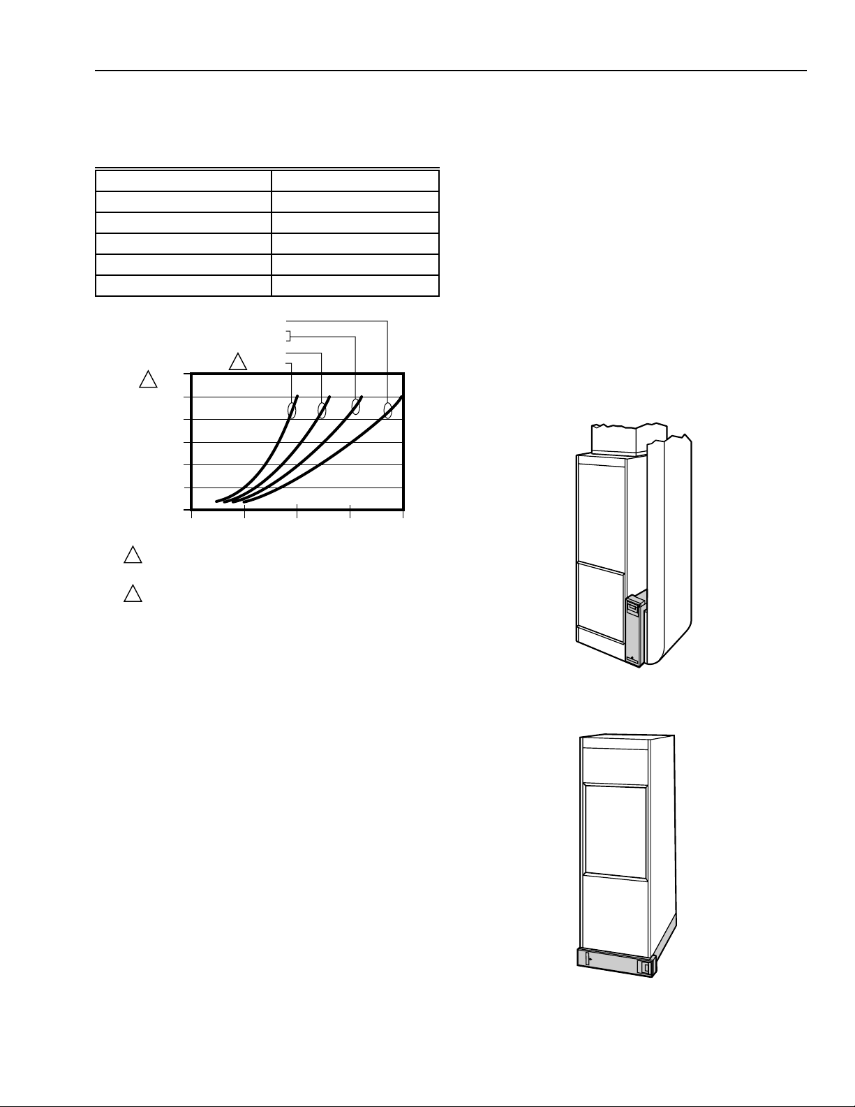
Replacement Media:
For optimum system performance, replace the filter every six
months (before heating season and before cooling season).
Adjust the schedule to you needs, but replace the filter at
least annually.
Filter Size (in.) Part Number
12.5 x 20 FC100A1052
16 x 25 FC100A1029
16 x 20 FC100A1003
20 x 25 FC100A1037
20 x 20 FC100A1011
FILTER SIZE
20 X 25
16 X 25
20 X 20
16 X 20
12.5 X 20
0.300
1
0.250
0.200
0.150
0.100
0.050
PRESSURE DROP (IN. WC)
0.000
0
WHEN FIRST INSTALLED. PRESSURE DROP INCREASES AS FILTER
1
BECOMES LOADED. REPLACE FILTER WHEN PRESSURE DROP
REACHES 0.5 IN. WC. (0.1 kPa).
2
AVAILABLE ONLY IN UNITED STATES.
2
500 1000 1500
AIRFLOW (CFM)
2000
M14709
Applications With Air Conditioning
Mount the media air cleaner upstream of the evaporator coil
in a cooling system. The filter will help to keep the coil clean
and reduce maintenance.
Applications With A Humidifier
The media air cleaner is compatible with humidifiers. Avoid
applications where water mist will reach the media. If an
atomizing humidifier is used, the filter media will require
replacement more often because of minerals in the water.
Choose Mounting Position
The media air cleaner can be mounted in any position, but the
arrow on the cartridge must point in the same direction as the
airflow. See Figs. 3-10 for proper location of the media air
cleaner for a variety of furnace installations. Note that the
media air cleaner cabinet is sturdy enough to easily support
the weight of the furnace and evaporator coil. See Fig. 4.
Fig. 2. Capacity, Pressure Drop and Area of
FC100A Filter Media.
PLANNING THE INSTALLATION
Location
The media air cleaner should be installed where all the air
passing through the system is circulated through it. The best
location is in the return air duct next to the blower
compartment so the media air cleaner can help to keep the
blower motor and evaporator coils clean. Do not mount in the
supply air duct.
For most efficient air cleaning, spread airflow evenly across
the face of the media. If the duct is a different size than the
media air filter cabinet, gradual transitions are required. If the
duct turns sharply just before the air filter, turning vanes are
required.
Choose a location that is readily accessible for checking and
replacing the filter. Allow at least 26 in. (660 mm) clearance in
front of the unit for removal of the cartridge.
Install the media air filter where the temperature will not
exceed the ratings in the Specifications.
Fig. 3. Highboy furnace, with side installation.
Media air filter is mounted vertically where return
enters side inlet of furnace.
M940A
Fig. 4. Highboy furnace, with installation beneath furnace.
Media air cleaner is mounted horizontally where return
enters from below.
3
68-0239EF–4
Page 4

F100 MEDIA AIR CLEANER
M941A
Fig. 5. Highboy furnace, with closet installation. Media air
cleaner is mounted vertically on furnace between furnace
and louvered return air opening in closet door.
M943A
Fig. 7. Counterflow furnace, with media air cleaner
mounted horizontally in return duct or plenum just
above furnace.
M942A
Fig. 6. Lowboy furnace, with media air cleaner mounted
horizontally in return plenum just above furnace and
opposite heating plenum.
68-0239EF–4
M944A
Fig. 8. Central fan installation, with media air cleaner
mounted horizontally in central return duct.
4
Page 5
M945A
20 DEGREE EXPANSION PER SIDE PER
FITTING (4 IN. PER RUNNING FOOT
[100 MM PER 300 LINEAR MM])
RETURN AIR
DUCT
TRANSITION FITTING
MEDIA AIR CLEANER CABINET
M947B
DUCT SIZE CHANGED GRADUALLY TO PREVENT TURBULENCE.
M948A
LESS
THAN
7 in.
(178 mm)
OFFSET
AT LEAST
7 in.
(178 mm)
1
1 REQUIRED TURNING VANES HELP DISTRIBUTE AIRFLOW EVENLY.
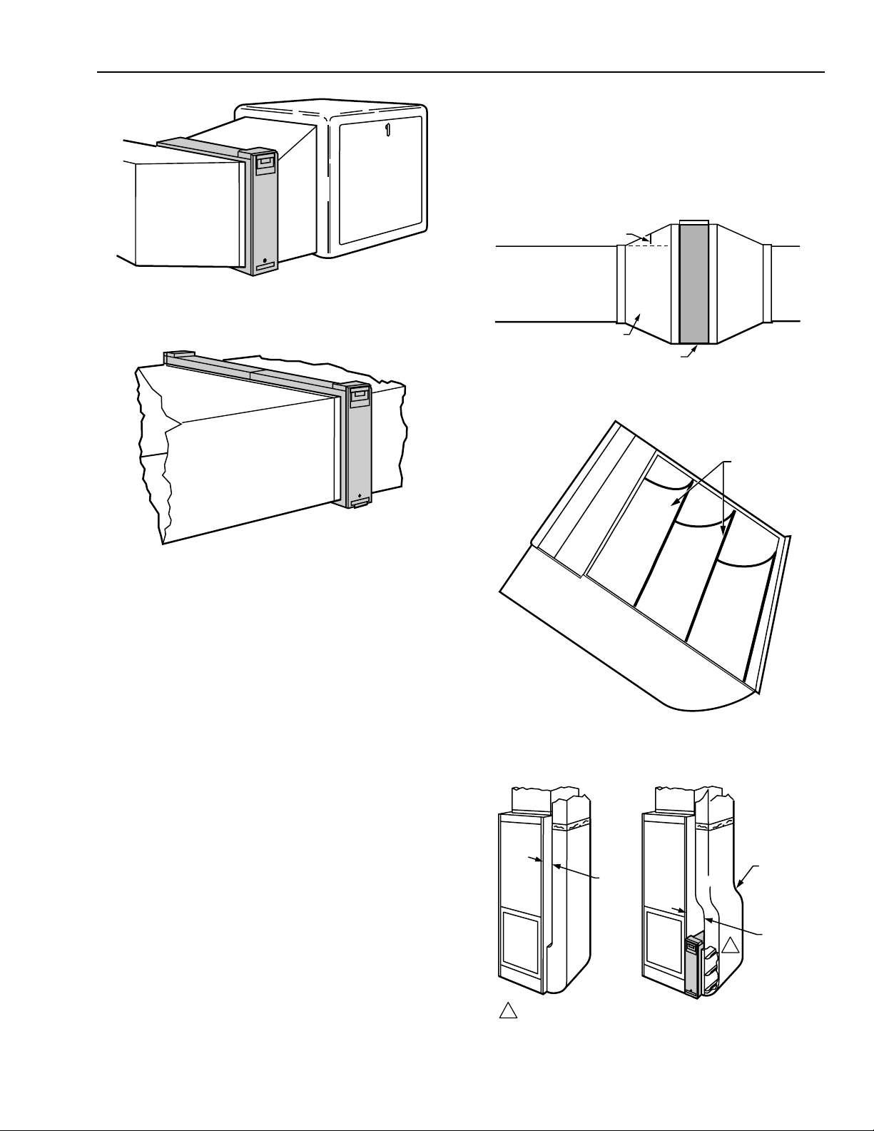
Fig. 9. Horizontal furnace, with media air filter mounted
vertically in return duct near furnace.
F100 MEDIA AIR CLEANER
Offsets
If the duct connection to the furnace in a side installation
allows less than 7 in. (178 mm) for mounting media air
cleaner cabinet, attach an offset to the elbow. See Fig. 13.
Fig. 11. Duct size changed gradually to prevent
turbulence.
TURNING
VANES
Fig. 10. Two or more media air cleaners used in a high
capacity system.
Determining Sheetmetal Requirements
The media air cleaner is adaptable to all new or existing
forced air heating and cooling systems used in residential
applications. Transitions or turning vanes may be required in
some applications for effective media air cleaner operation.
Transitions
Tr ansitions are needed when the duct is a different size than
the media air cleaner cabinet. Follow these guidelines when
fabricating:
1. Use gradual transitions to reduce air turbulence and
increase efficiency. See Fig. 11.
2. Use no more than 20 degrees (about 4 in. per running
ft. (100 mm per 300 linear mm)) of expansion on each
side of a transition fitting.
Turning Vanes
If the media air cleaner is installed next to an elbow or angle
fitting, add turning vanes inside the angle to distribute airflow
more evenly across the face of the media. See Fig 12.
M946A
M5651
Fig. 12. Turning vanes installed in bend help distribute
airflow evenly over face of media.
Fig. 13. Typical use of duct offset to make room for
media air cleaner.
5
68-0239EF–4
Page 6

F100 MEDIA AIR CLEANER
INSTALLATION AND CHECKOUT
When Installing this Product…
1. Read these instructions carefully. Failure to follow them
could damage the media air filter or cause a hazardous
condition.
2. Check the ratings given in the instructions and on the
media air cleaner to make sure the product is suitable
for your application.
3. Installer must be a trained, experienced service
technician.
Remove Furnace Filter And Clean Blower
Compartment
Before starting the installation, remove and discard the
existing furnace filter (if used). Thoroughly clean the blower
compartment. If possible, power vacuum the ductwork to
remove accumulated dust in an occupied home or remove
construction dirt in a new home. The media air cleaner cannot
remove dirt that has settled in the blower compartment and
distribution ducts.
Install The Cabinet
The following procedure describes a typical side installation
on an existing highboy furnace. Alternate procedures are
noted as appropriate. Other changes in installation
procedures may be necessary to complete your installation.
Fasten Cabinet To Ductwork
Fasten side of cabinet to the ductwork using sheet-metal
screws, rivets, or slip joints, as appropriate.
Connect Ductwork
Connect the vertical duct section to the elbow. If the vertical
drop of the duct is less than 7 in. (178 mm) from the side of
the furnace, shorten the horizontal trunk or attach an offset
fitting to the elbow. See Fig. 12. When ductwork is properly
aligned, connect the vertical duct to the horizontal trunk.
Seal Joints
Seal all joints in the return air system between the media air
filter and the furnace to prevent dust from entering the clean
airstream.
Install Filter Cartridge
Slide the filter cartridge into the cabinet, making sure the
arrow on the cartridge points in the direction of air flow.
Replace access door. Insert the tab on the bottom of the door
into the slot in the cabinet. Swing the door closed and press it
into place.
Install W8600A AIRWATCH™ Indicator
(Included with some models)
Review The Installation Plan
Temporarily place the cabinet on the floor, oriented as it will
be when installed. Insert and remove the cartridge to make
sure the plan allows adequate clearance for easy removal
and replacement of the cartridge.
Make sure that shop-fabricated sheetmetal components, such
as turning vanes, are available.
Fasten The Cabinet To The Furnace
Align the cabinet with the return air opening. Place blocks
under the cabinet, as necessary, to make sure the unit sits
securely. Create an opening in the furnace to match the
cabinet opening. Attach the cabinet securely to the furnace.
Attach the unit directly or fit a starting collar in the furnace
opening. Either drill holes and fasten with sheetmetal screws
or rivets, or use slip joints. If you are drilling holes, use a
locking pliers to help hold the unit in place during drilling.
Install Turning Vanes
Install turning vanes to help distribute air equally over the full
surface of the upstream side of the media. Install them
whenever an abrupt 90 degree elbow is installed directly
against the media air cleaner cabinet.
Mount the W8600A next to the thermostat or any other
convenient location in the living area of the home. The device
is battery-operated so has no electrical requirements.
Remove the device from the base and mark the mounting
holes, using the base as a template. Drill the holes. Position
the base over the holes and install the mounting screws
provided. Tighten the screws until the base is mounted firmly
on the wall. Replace the device onto the base.
Set the DIP switches on the back of the W8600A according to
the equipment installed in the home. Use the default settings
when all devices (air cleaner, UV air treatment system, and
humidifier) are installed. Or move the DIP switch to off (left)
when a device is not installed.
NOTE: The UV air treatment system and the humidifier
settings are set for one year. The air cleaner settings
are selectable according to homeowner activities
and schedule.
Set the air cleaner filter time DIP switches for 3, 6, 9 or 12
months according to the information on the back of the
device. Leave the factory default DIP switch settings to
change the filter every three months. If no air cleaner filter is
installed, move DIP switch 4 and 5 settings to off (left).
68-0239EF–4
6
Page 7

F100 MEDIA AIR CLEANER
Install two AAA alkaline batteries (provided) in the harness on
the back of the device. Observe that the device performs a
self-test, beeping and flashing the LC display individually for
each device (air cleaner, UV air treatment system, humidifier)
installed in the home. Then press and hold the black reset
button on the bottom of the device for five seconds or until the
display stops flashing to start the timers. Observe the battery
LCD: on solidly means that the unit is correctly powered;
flashing indicates that the battery requires replacing.
Checkout
Visually check the installation. Make sure:
• Airflow is in the direction of the arrow on the media air filter
cartridge.
•Turning vanes and transitions, if used, are properly
installed.
• Joints in sheetmetal between media fir filter and fur-nace
are sealed.
• All sheetmetal connections are complete.
•Original furnace filter has been removed and blower
compartment is cleaned.
Replace any access doors removed during the Installation or
Checkout.
Run the furnace or cooling system through one complete
cycle to make sure the system operates as desired.
Maintenance
The W8600A beeps every fifteen minutes when an LCD is
flashing. Replace the part in the system that corresponds with
the flashing LCD.
NOTE: When batteries need replacing, replace them within
30 seconds of removal to maintain the correct
indicator time. After 30 seconds of replacing the
batteries, if the LCD is blank, remove and install new
batteries. For other parts, press and hold the black
button on the bottom of the device to reset the timer
after replacing parts.
The media filter must be replaced when pressure drop across
the media filter reaches 0.5 in. w.c. (0.1 kPa). or at least
annually. If the media air cleaner is installed downstream from
an atomizing humidifier or if the installation includes both
heating and cooling, more frequent replacement may be
necessary. Clogged media must be replaced promptly to
avoid restricting airflow and reducing efficiency of the heatingcooling system. Record the replacement date in the space
provided on the replacement media filter.
LCD If arrow is flashing or
unit is beeping
Battery Batteries need changing. Changing batteries within 30 seconds of removing
old batteries to maintain correct indicator time.
Air Cleaner Media filter needs replacing. Pressing and holding reset button for 10 seconds or
until arrow is no longer displayed.
UV Air Treatment UV lamps need replacing in UV air
treatment system.
Humidifier Humidifier pad needs replacing.
Reset by
7
68-0239EF–4
Page 8

Automation and Control Solutions
Honeywell International Inc.
1985 Douglas Drive North
Golden Valley, MN 55422
68-0239EF–4 G.H. Rev. 7-04
Honeywell Limited-Honeywell Limitée
35 Dynamic Drive
Scarborough, Ontario
M1V 429
Printed in U.S.A. on recycled
paper containing at least 10%
post-consumer paper fibers.
M18621A
Page 9

Filtre à air à élément filtrant à fibres F100
APPLICATION
Le filtre à air à élément filtrant à fibres F100 retient une importante
quantité de particules contenues dans l’air qui le traverse.
FICHE TECHNIQUE
IMPORTANT
Les caractéristiques techniques indiquées dans la
présente publication ne comprennent pas les tolérances
normales de fabrication. Par conséquent, il se peut que
l’appareil ne corresponde pas exactement aux
caractéristiques indiquées. De même, le produit a été
mis à l’essai et étalonné dans des conditions entièrement
contrôlées et on peut s’attendre à de légères différences
de fonctionnement si ces conditions sont modifiées.
Modèles :
F100F filtre à air à élément filtrant à fibres avec boîtier, porte
d’accès, médium filtrant en papier accordéon. Certaines
modèles comprennent un indicateur AirWatch
F100B filtre à élément filtrant à fibres avec boîtier et porte
d’accès.
Application :
Convient aux appareils de chauffage à air pulsé au gaz, au
mazout et à l’électricité et aux compresseurs de
refroidissement. Peut être utilisé dans un système à pompe à
chaleur si le filtre est remplacé à intervalle régulier pour éviter
une trop grande chute de pression. Non recommandé dans
les systèmes ou une chute de pression peut nuire.
MD
W8600A.
DONNÉES TECHNIQUES
CARACTÉRISTIQUES
• Filtre à fibres à haut rendement (compris avec certains
modèles) qui retient des particules dont la taille fait
aussi peu que 0,3 micron.
• Efficacité et capacité de rétention du FC100A établies
d’après la norme 52.2-1999 de l’American Society of
Heating, Refrigerating and Air-Conditioning Engineers.
• Convient à tous les systèmes de chauffage à air pulsé
au gaz, au mazout ou à l’électricité et aux
compresseurs de refroidissement allant jusqu’à 5
tonnes.
• S’installe dans la gaine de reprise d’air.
• Le boîtier résistant peut recevoir le poids d’un
appareil de chauffage résidentiel et d’un serpentin
d’évaporation.
• Ne requiert aucun raccordement électrique.
• S’installe dans n’importe quelle position.
• N’exige aucun entretien à l’exception du
remplacement périodique du filtre à fibres.
• Remplacement simple et rapide du filtre à fibres.
• Peut par la suite être remplacé facilement par un
modèle à rendement plus élevé ou par un filtre à air
électronique. (Prendre note que les modèles 25 x 20 po
et 25 x 22 po ne peuvent pas être remplacés par un
filtre à air électronique.)
Efficacité du FC100A :
Efficacité établie d’après la norme 52.2-1999 de l’American
Society of Heating, Refrigerating and Air-Conditioning
Engineers.
Efficacité initiale : 25 % (particules de 0,3 micron).
Rendement minimum rapporté : 10 à 492 pi
Médium filtrant :
Papier plié en accordéon pour une plus grande capacité.
Capacité et chute de pression :
Voir la Fig. 2.
Chute de pression initiale : 0,233 po c.e. à 492 pi
Température ambiante nominale :
-40 à 60 oC (-40 à 140 oF).
Encombrement :
Voir la Fig. 1.
3
/min.
3
/min.
® Marque de commerce enregistrée aux États-Unis
Copyright © 2004 Honeywell International Inc. * Tous droits réservés
68-0239EF-4
Page 10

FILTRE À AIR À ÉLÉMENT FILTRANT À FIBRES F100
Installation :
S’installe dans n’importe quelle position dans la gaine de
reprise d’air, habituellement près du compartiment du
ventilateur de l’appareil de chauffage. Le boîtier est
suffisamment résistant pour recevoir le poids d’un appareil de
chauffage résidentiel et d’un serpentin d’évaporation.
Homologation :
Underwriters Laboratories Inc., répertorié selon la norme
UL900, classe 2.
1
(29)
1
8
DIM. A
(SEE TABLE)
Possibilité de mise à niveau :
Le F100F fait appel au même boîtier que le filtre à air
électronique F50. La mise à niveau peut nécessiter
l’installation d’un clavette de cellule, de cellules électroniques,
d’écrans protecteurs; selon les modèles, il faudra également
installer et raccorder le bloc d’alimentation. (Prendre note que
les modèles 25 x 20 po et 25 x 22 po ne peuvent pas être
remplacés par un filtre à air électronique.)
Accessoire :
Indicateur AirWatch
MD
W8600A (en option avec certaines
modèles).
DIM. B
(SEE TABLE)
DIM. D
(22)
25 1/2
20 1/2
25 1/2
20 1/2
13 1/8
20 5/8
22 1/2
MF14710A
7
8
6
(171)
3
4
7
5
8
8
(22)
(16)
MM
406 X 635
406 X 508
508 X 635
508 X 508
508 X 318
635 X 508
635 X 559
F100 SIZE
IN.
16 X 25
16 X 20
20 X 25
20 X 20
20 X 12 1/2
25 X 20
25 X 22
DIM. C (SEE TABLE)
DIM. D (SEE TABLE)
DIM. A
MM IN. MM IN.
367
14 7/16
367
14 7/16
468
18 7/16
468
18 7/16
468
18 7/16
592
23 5/16
592
23 5/16
DIM. B
411
411
513
513
513
638
638
16 3/16
16 3/16
20 3/16
20 3/16
20 3/16
25 1/8
25 1/8
DIM. C
MM IN. MM IN.
591
457
591
457
276
467
514
23 1/4
18 1/4
23 1/4
18 1/4
10 7/8
18 3/8
20 1/4
648
521
648
521
333
524
572
Fig. 1. Encombrement du filtre à air en mm (po).
POUR COMMANDER
Au moment d’acheter des produits de modernisation et de remplacement auprès de votre grossiste ou distributeur TRADELINE©,
consultez le catalogue TRADELINE ou les tarifs pour obtenir le numéro de pièce.
Prière d’adresser toute question additionnelle, demande d’information ou commentaires sur les produits et services par écrit ou par
téléphone :
1. Aux services à la clientèle de Honeywell
Honeywell 1885 Douglas Drive North, MN10-1461
Golden Valley, MN 55422-4386
2. Ou visiter notre site Web à www.honeywell.com/yourhome/
Au Canada : Honeywell Limited-Honeywell Limitée, 35 Dynamic Drive, Scarborough, Ontario M1V 4Z9
Points de vente et de service dans toutes les grandes villes du monde. Usines en Allemagne, en Australie, au Canada, en
Espagne, aux États-Unis, en Finlande, en France, au Japon, au Mexique, aux Pays-Bas, au Royaume-Uni et à Taiwan.
68-0239EF–4
2
Page 11

FILTRE À AIR À ÉLÉMENT FILTRANT À FIBRES F100
M939A
Médium filtrant de rechange :
Pour assurer au système un fonctionnement optimal,
remplacer le filtre tous les six mois (avant la saison de
chauffage et avant la saison de refroidissement). Modifier le
calendrier selon les besoins, mais remplacer le filtre au moins
une fois l’an.
Taille du filtre (en po) Numéro de pièce
12.5 x 20 FC100A1052
16 x 25 FC100A1029
16 x 20 FC100A1003
20 x 25 FC100A1037
20 x 20 FC100A1011
TAILLE DU FILTRE
0.300
1
0.250
0.200
0.150
0.100
0.050
0.000
CHUTE DE PRESSION (PO C.E.)
0
APRÈS L’INSTALLATION, LA CHUTE DE PRESSION AUGMENTE À MESURE
1
QUE LE FILTRE SE CHARGE DE PARTICULES. REMPLACER LE FILTRE
LORSQUE LA CHUTE DE PRESSION ATTEINT 1 kPa (0,5 po c.e.).
2
OFFERT AUX ÉTATS-UNIS SEULEMENT.
20 X 25
16 X 25
20 X 20
16 X 20
2
12.5 X 20
500 1000 1500
DÉBIT D’AIR (EN pi3/min)
2000
MF14709A
Applications – appareil de refroidissement
Le filtre à air devrait être installé en amont du serpentin de
l’évaporateur. Le filtre à air aidera à garder le serpentin propre
et permettra de réduire la fréquence de l’entretien.
Applications – humidificateur
Le filtre à air convient aux systèmes avec humidificateurs.
Éviter les installations où l’eau vaporisée peut atteindre le
médium filtrant. Dans le cas d’une installation avec
humidificateur atomiseur, il faudra remplacer le médium
filtrant plus souvent en raison des sédiments que contient
l’eau.
Choisir la position d’installation du filtre
Le filtre à air à élément filtrant à fibres peut être installé dans
n’importe quelle position, mais les flèches figurant sur la
cartouche doivent pointer dans le même sens que celui de
l’écoulement de l’air. Voir les figures 3 à 10 pour observer
l’emplacement adéquat du filtre à air à élément filtrant à fibres
selon le type d’appareil de chauffage. Il est à noter que le
boîtier du filtre à air à élément filtrant à fibres est robuste et
qu’il peut facilement recevoir le poids de l’appareil de
chauffage et du serpentin d’évaporation. Voir la Fig. 4.
Fig. 2. Efficacité du filtre à air, chute de pression à divers
débits d’air.
PLANIFICATION DE L’INSTALLATION
Emplacement
Installer le filtre à air de manière que tout l’air qui passe dans le
système puisse circuler dans le filtre. Le meilleur endroit est la
gaine de retour d’air, à côté du compartiment de ventilation; à
cet endroit, le filtre à air contribuera en effet à garder le moteur
du ventilateur et les serpentins de l’évaporateur plus propres.
Ne pas installer le filtre dans la gaine de soufflage.
Le filtrage de l’air sera plus efficace si le débit d’air est réparti
uniformément sur la surface du filtre. Si la gaine et le boîtier du
filtre à air n’ont pas les mêmes dimensions, il est préférable
d’installer des raccords de transition. Si la gaine présente un
angle aigu juste avant le filtre à air, il est recommandé d’utiliser
des déflecteurs.
Choisir un emplacement facile d’accès pour la vérification et le
remplacement du filtre. Prévoir un dégagement d’au moins
660 mm (26 po) sur le devant de l’appareil pour le retrait de la
cartouche.
Installer le filtre à air à élément filtrant à fibres à un endroit où
la température ne dépasse pas les limites indiquées dans la
fiche technique.
Fig. 3. Appareil de chauffage à caissons superposés.
Filtre à air installé sur le côté à la verticale, à l’endroit où
entre l’air repris, sur le côté de l’appareil de chauffage.
M940A
Fig. 4. Appareil de chauffage à caissons superposés.
Filtre à air installé sous l’appareil de chauffage à
l’horizontale, à l’endroit où entre l’air repris, au bas de
l’appareil de chauffage.
3
68-0239EF–4
Page 12

FILTRE À AIR À ÉLÉMENT FILTRANT À FIBRES F100
M941A
Fig. 5. Appareil de chauffage à caissons superposés,
dans une armoire. Filtre à air installé sur le côté à la
verticale sur l’appareil de chauffage, entre l’appareil de
chauffage et la grille de reprise d’air placée dans
l’ouverture de la porte de l’armoire.
M943A
Fig. 7. Appareil de chauffage à contre-courant. Filtre à air
installé à l’horizontale dans la gaine de reprise d’air ou
dans le plénum juste au-dessus de l’appareil de
chauffage.
M942A
Fig. 6. Appareil de chauffage à caissons juxtaposés. Filtre
à air installé à l’horizontale dans le plénum d’air repris
juste au-dessus de l’appareil de chauffage, face au
plénum d’alimentation.
68-0239EF–4
4
M944A
Fig. 8. Appareil de ventilation centrale. Filtre à air installé
à l’horizontale dans une gaine de reprise centrale.
Page 13

M945A
MF5651
DÉFLECTEURS
MF947C
MODIFICATION GRADUELLE DE LA TAILLE DE LA GAINE D’AIR
EN VUE DE RÉDUIRE LA TURBULENCE.
EXPANSION DE 20 DEGRÉS DE CHAQUE CÔTÉ,
PAR RACCORD (100 mm par 300 mm linéaires)
(4 po par pied linéaire).
GAINE DE REPRISE D’AIR
RACCORD DE TRANSITION
BOÎTIER DU FILTRE À AIR À ÉLÉMENT
FILTRANT À FIBRES
Fig. 9. Appareil de chauffage horizontal. Le filtre à air est
monté à la verticale à l’endroit où entre l’air repris près
de l’appareil de chauffage.
FILTRE À AIR À ÉLÉMENT FILTRANT À FIBRES F100
Fig. 11. Modification graduelle de la taille de la gaine d’air
en vue de réduire la turbulence.
Fig. 10. Deux filtres à air à élément filtrant à fibres ou
plus installés dans un système à haut rendement.
Raccords de gaines requis
Le filtre à air se combine à tout système résidentiel de
chauffage, de refroidissement et de ventilation à air pulsé
neuf ou en place. Des raccords de transition ou de dérivation
et des déflecteurs peuvent être nécessaires pour assurer un
meilleur rendement dans certaines applications.
Raccords de transition
Des raccords de transition sont nécessaires lorsque les
dimensions de la gaine et du boîtier du filtre à air sont
différentes.
1. Les raccords de transition réduisent la turbulence et
augmentent l’efficacité. Voir la Fig. 11.
2. L’expansion maximale doit être de 20 degrés (environ
100 mm par 300 mm linéaires [4 po par pied linéaire])
de chaque côté du raccord de transition.
Déflecteurs
Si le filtre à air est installé près d’un coude (raccord à angle),
installer les déflecteurs à l’intérieur du coude pour assurer
une distribution d’air plus uniforme à la surface du filtre. Voir la
Fig. 12.
Raccords de dérivation
Si le raccord entre la gaine et l’appareil dans le cas d’une
installation sur le côté offre un dégagement inférieur à 178
mm (7 po) pour le boîtier du filtre à air, ajouter un raccord de
dérivation au coude. Voir la Fig. 13.
M946A
Fig. 12. Utilisation de déflecteurs pour contribuer à
assurer une distribution d’air plus uniforme à la surface
du filtre.
1
RACCORD
DE DÉRIVATION
AU MOINS
178 mm
(7 po)
MF948A
MOINS DE
178 mm
(7 po)
1 LES DÉFLECTEURS ASSURENT UNE MEILLEURE RÉPARTITION D’AIR.
Fig. 13. Utilisation typique d’un raccord de dérivation
pour assurer un dégagement suffisant au filtre à air à
élément filtrant à fibres.
5
68-0239EF–4
Page 14

FILTRE À AIR À ÉLÉMENT FILTRANT À FIBRES F100
INSTALLATION
AVANT D’INSTALLER CE PRODUIT...
1. Lire attentivement les instructions. Le fait de ne pas les
suivre risque d’endommager le produit ou de constituer
un danger.
2. Vérifier les caractéristiques nominales indiquées dans
les instructions et sur le produit, et s’assurer que celuici correspond bien à l’application prévue.
3. L’installateur doit être un technicien d’expérience ayant
reçu la formation pertinente.
4. Une fois l’installation terminée, vérifier le
fonctionnement du produit comme l’indiquent les
présentes instructions.
Retirer le filtre de l’appareil de chauffage et
nettoyer le compartiment du ventilateur
Avant de procéder à l’installation, retirer et mettre de côté le
filtre actuel de l’appareil de chauffage (s’il existe). Nettoyer à
fond le compartiment du ventilateur. Si c’est possible, passer
l’aspirateur dans le système de gaines pour éliminer la
poussière accumulée dans une maison déjà construite ou la
saleté due à la construction dans une maison neuve. Le filtre
à air à élément filtrant à fibres ne peut éliminer la poussière
accumulée dans le compartiment du ventilateur et les gaines
de distribution.
Installer les déflecteurs
Installer les déflecteurs pour assurer une distribution uniforme
de l’air sur toute la surface amont du médium filtrant. Il faut
les installer à l’intérieur du coude à 90 degrés, montés
directement sur le boîtier du filtre à air.
Fixer le boîtier au système de gaines
Fixer l’autre côté du boîtier sur le coude à l’aide de rivets, de
vis pour tôle, ou d’écrous coulissants, au besoin.
Raccorder le filtre à la gaine
Raccorder la section verticale de la gaine au coude. Si la
portion verticale de la gaine est à moins de 178 mm (7 po) du
côté de l’appareil de chauffage, raccourcir la portion
horizontale ou fixer un raccord de dérivation au coude. Voir la
Fig. 13. Lorsque la gaine d’air est correctement alignée,
raccorder la partie verticale à la partie horizontale.
Sceller les joints
Sceller tous les joints du système de reprise d’air entre le
filtre à air et l’appareil de chauffage pour empêcher la
poussière de pénétrer dans le courant d’air propre.
Installer la cartouche du filtre
Faire glisser la cartouche du filtre dans le boîtier et vérifiant
que la flèche figurant sur la cartouche correspond bien au sens
d’écoulement de l’air.
Installer le boîtier
Remettre la porte d’accès en place, insérer la languette au bas
L’installation d’un filtre sur le côté d’un appareil de chauffage
à caissons juxtaposés est décrite ci-dessous. D’autres
explications sont fournies au besoin. Des modifications
peuvent s’avérer nécessaires dans le cas d’un autre système.
de la porte dans la fente pratiquée sur le boîtier. Refermer la
porte et appuyer pour qu’elle soit solidement en place.
Installation de l’indicateur AIRWATCH
W8600A (compris avec certaines modèles
Passer en revue le plan de l’installation
Déposer le boîtier sur le sol, orienté comme il le sera une fois
l’installation terminée. Insérer et retirer la cartouche pour
vérifier que les plans offrent un dégagement suffisant au
retrait et au remplacement de la cartouche.
S’assurer d’avoir sous la main des éléments de tôle
préfabriqués, comme des déflecteurs.
F100)
L’indicateur W8600A peut être installé près du thermostat ou à
tout autre endroit pratique dans la maison. C’est un appareil
alimenté par pile qui n’exige aucun raccord électrique.
Retirer l’appareil de sa base et marquer l’emplacement des
trous de fixation en utilisant la base comme gabarit. Percer les
trous. Placer la base vis-à-vis des trous et installer les vis de
fixation fournies. Serrer les vis jusqu’à ce que la base soit
fermement fixée au mur. Remettre l’appareil sur sa base.
MD
Fixer le boîtier à l’appareil de chauffage
Aligner le boîtier sur l’ouverture pour la reprise d’air. Placer
des blocs sous le boîtier pour que l’appareil soit bien soutenu
et de niveau. Percer une ouverture dans l’appareil de
chauffage correspondant à celle du boîtier du filtre à air. Fixer
solidement le boîtier à l’appareil de chauffage soit
directement (voir illustration), soit à l’aide d’un collier de
démarrage dans l’appareil de chauffage. Percer des trous et
fixer l’appareil à l’aide de rivets ou de vis pour tôle ou utiliser
des écrous coulissants. S’il faut percer des trous, utiliser une
pince-étau pour maintenir l’appareil en place pendant cette
opération.
68-0239EF–4
6
Il faut régler les microrupteurs situés au dos du W8600A en
fonction des systèmes installés dans la maison. Utiliser les
positions par défaut réglées en usine lorsque tous les appareils
(filtre à air, système de traitement de l’air aux ultraviolets,
humidificateur) sont installés dans la maison. Déplacer les
microrupteurs à la position de gauche (en position d’arrêt OFF) lorsqu’un des appareils n’est pas installé dans la maison.
REMARQUE. Les réglages du système de traitement de l’air
aux ultraviolets et de l’humidificateur sont valables
pour une année. Les réglages du filtre à air peuvent
être modifiés en fonction des activités et des
besoins du propriétaire.
Page 15

FILTRE À AIR À ÉLÉMENT FILTRANT À FIBRES F100
Suivre les réglages qui figurent au dos du W8600A pour régler
les microrupteurs pour 3, 6, 9, ou 12 mois. Utiliser les réglages
de l’usine pour remplacer le filtre à fibres tous les trois mois,
selon le nombre de mois désirés. S’il n’y a pas de filtre à air,
placer les microrupteurs 4 et 5 vers la gauche (en position
d’arrêt – OFF).
Placer deux piles alcalines AAA (fournies) dans le porte-piles
au dos de l’appareil. Observer l’appareil procéder à un test
automatique : les indicateurs à cristaux liquides
correspondant à chacun des appareils installés dans la
maison (filtre à air, système de traitement de l’air aux
ultraviolets, humidificateur) clignotent à tour de rôle. Pour
Indication Si la flèche clignote ou si
l’appareil émet un bip…
Battery (pile) Il faut changer les piles. Changer les piles 30 secondes après avoir retiré les
Air Cleaner (filtre à air) Il faut remplacer le filtre à fibres ou
nettoyer le filtre à air électronique.
UV Air Treatment (traitement
de l’air aux ultraviolets)
Humidifier (humidificateur) Il faut remplacer les tampons de
Il faut remplacer les lampes UV du
système de traitement de l’air aux
ultraviolets.
l’humidificateur.
remettre la minuterie à zéro, il faut ensuite appuyer sur le
bouton de réarmement et le maintenir enfoncée pendant cinq
secondes ou jusqu’à ce que l’affichage cesse de clignoter.
Observer l’indicateur à cristaux liquides des piles. S’il reste
allumé, l’appareil est correctement alimenté. S’il clignote, il
faut remplacer les piles.
REMARQUE.
Le W8600A émet un signal sonore lorsqu’une des
flèches clignote pour avertir l’utilisateur qu’il faut vérifier
quel appareil doit être nettoyé. Après l’entretien, appuyer
sur le bouton de réarmement au bas du W8600A et le
retenir pendant 10 secondes pour réarmer la minuterie.
Ce qu’il faut faire
anciennes piles pour que l’intervalle d’avertissement
reste le bon.
Appuyer sur le bouton de réarmement et le retenir
pendant 10 secondes ou jusqu’à ce que la flèche ne
soit plus allumée.
VÉRIFICATION
Vérifier l’installation visuellement comme suit :
•L’air circule dans le sens indiqué par la flèche figurant
sur la cartouche du filtre à air à élément filtrant à fibres.
• Les déflecteurs et les raccords de transition, le cas
échéant, sont bien installés
• Les joints en tôle entre le filtre à air et l’appareil de
chauffage sont scellés.
•Tous les raccords en tôle ont été posés.
• Le filtre original a été retiré et le compartiment du
ventilateur a été nettoyé.
Remettre en place toutes les portes d’accès retirées au
moment de l’installation.
Faire fonctionner l’appareil de chauffage ou de refroidissement
pendant un cycle complet pour vérifier que le système
fonctionne comme il se doit.
Maintenance
Le W8600A émet un signal sonore toutes les quinze minutes
lorsqu’un des indicateurs à cristaux liquides clignote. Il faut à
ce moment remplacer la pièce du système qui correspond à
l’indicateur qui clignote.
REMARQUE. Lorsqu’il faut remplacer les piles, les
remplacer en moins de 30 secondes après leur
retrait pour conserver le bon intervalle
d’avertissement. Si l’écran à cristaux liquides reste
vide 30 secondes après le remplacement des piles,
retirer les piles et en installer de nouvelles. Pour les
autres pièces, appuyer sur le bouton de
réarmement situé sur la partie inférieure de
l’indicateur et le maintenir enfoncé pour remettre la
minuterie à zéro après avoir remplacé les pièces.
Le filtre à air à élément filtrant à fibres doit être remplacé
lorsque la chute de pression dans le filtre atteint 0,5 po c.e.
(1 kPa); il faut à tout le moins le remplacer une fois par
année. Si le filtre à fibres est installé en aval d’un
humidificateur atomiseur, des remplacements plus fréquents
pourront être nécessaires. Il faut remplacer un filtre obstrué
le plus rapidement possible pour éviter d’empêcher
l’écoulement de l’air et de réduire l’efficacité du système de
chauffage-refroidissement. Inscrire la date du remplacement
dans l’espace prévu à cet effet sur le filtre à fibres de
rechange.
7
68-0239EF–4
Page 16
Honeywell
Offrez à votre famille un air ambiant de
meilleure qualité en faisant appel aux
solutions Honeywell. Confort et
tranquillité d’esprit seront au rendez-vous.
Système de traitement d’air aux ultraviolets
Éliminez les microbes contenus dans l’air et
empêchez les spores de moisissures de croître
sur les serpentins de refroidissement
Filtre à air pour toute la maison
Emprisonnez une bonne partie des particules
contenues dans l’air
Humidificateur pour toute la maison
Humidifiez l’air trop sec, maintenez l’humidité
ambiante pour réduire les effets
négatifs sur la santé
Solutions de régulation et d’automatisation
Honeywell International Inc.
1985 Douglas Drive North
Golden Valley, MN 55422
68-0239EF–4 G.H. 7-04
Honeywell Limited – Honeywell Limitée
35, Dynamic Drive
Scarborough (Ontario)
M1V 4Z9
Système de régulation par zones
Réglez la température ambiante par zones pour
plus de commodité et un confort accru
Échangeur d’air PerfectWindow®
Aérez la maison pour que l’air soit plus sain
tout en réduisant la perte d’énergie
Thermostat programmable
Économisez jusqu’à 30 % du coût annuel de
l’énergie grâce à ce thermostat d’installation facile*
* selon l’emplacement géographique et l’utilisation
Imprimé aux États-Unis sur du
papier recyclé composé d’au moins
10 % de fibres post-consommation.
 Loading...