

Page 1
HWLKS-C-M-1918
Honeywell
- 1 -
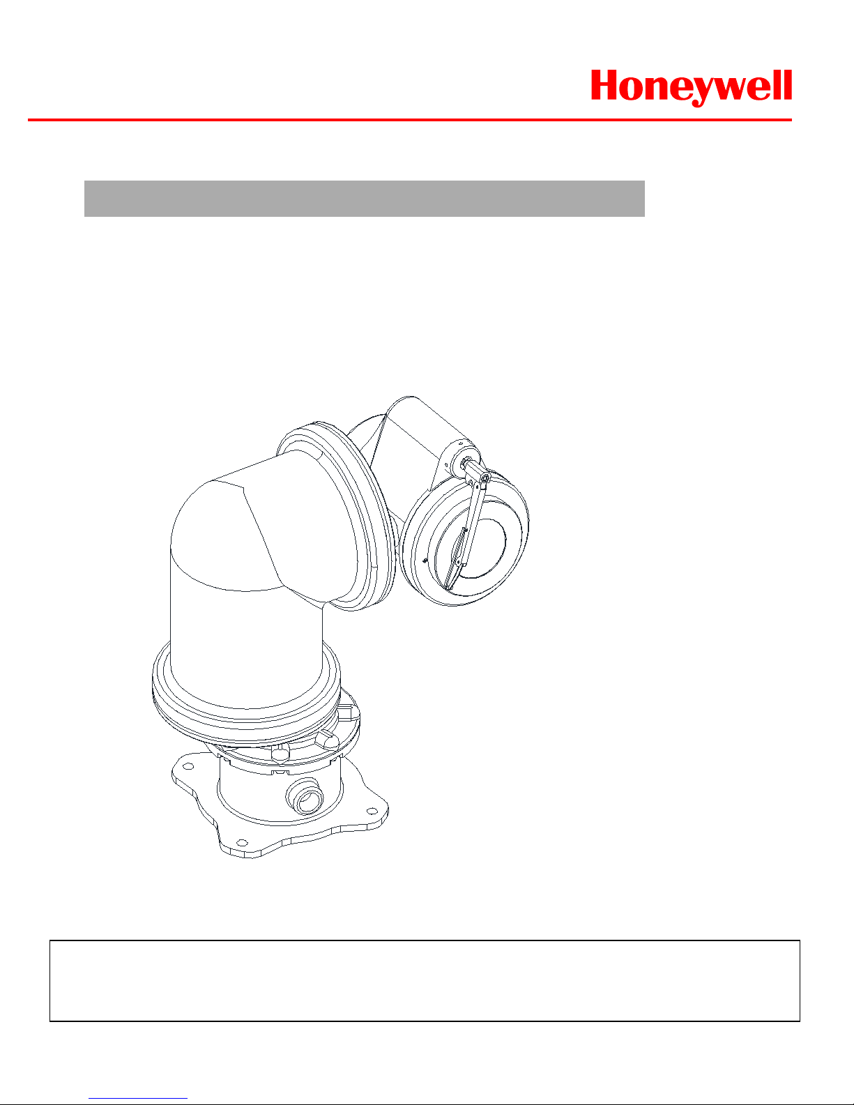
INSTALLATION&OPERATION GUIDE BOOK
EXPTZ Camera
Explosive proof Security Camera
The EXPTZ Series follow the stringent explosion-proof requirements with creative mechanical strength and
design. Moreover, the EXPTZ explosion-proof system is designed to meet the rigorous requirements of
explosion-proof electrical equipment installed in hazardous locations. The system has built-in True Day
&Night zoom camera with programmable Camera setting, Video Flip and BMB
TM
(Black Masking BLC).
(HIGH SPEED)
Page 2

HWLKS-C-M-1918
Honeywell
- 2 -
Important Safety Instructions ----------------------------------------------------------Method of Installation ---------------------------------------------------------------------Maintenance ----------------------------------------------------------------------------------Base Schematic -----------------------------------------------------------------------------Wire and Power Connection Guide ---------------------------------------------------Simple Function Control Guide --------------------------------------------------------Program and Operation -------------------------------------------------------------------Specifications --------------------------------------------------------------------------------Remote Controller --------------------------------------------------------------------------Optional Accessories ---------------------------------------------------------------------EXWJ400 Schematic & Operating ---------------------------------------------------Dimensions ------------------------------------------------------------------------------------Product Warranty Guide --------------------------------------------------------------------
Contents
3
4
6
9
10
11
13
34
36
37
41
43
45
Page 3
HWLKS-C-M-1918
Honeywell
- 3 -
Important Safety Instructions
1. Install and use this system after reading these instruction thoroughly.
2. Keep these instructions.
3. Install in accordance with the manufacture’s instruction.
4. Take care of all Cautions and Warnings.
5. Use stainless steel hardware to fasten the mount to outdoor surfaces.
6. A readily accessible disconnect device shall be incorporated in the building installation
wiring.
7. Only use replacement parts recommended by Honeywell.
8. The maximum ambient temperature range is -20℃ to 50℃.
RISK OF ELECTRIC SHOCK
DO NOT OPEN
CAUTION
CAUTION : TO REDUCE THE RISK OF ELECTRIC SHOCK.
DO NOT REMOVE COVER(OR BACK).
NO USER SERVICEABLE PARTS INSIDE
REFER SERVICING TO QUALIFIED SERVICE PRERSONNEL
Explanation of Graphical Symbols.
This symbol is intended to alert the user to the presence of uninsulated
“dangerous voltage” within the product’s enclosure that may be of sufficient
magnitude to constitute a risk of electric shock to persons.
This symbol is intended to alert the user to the presence of important
operating and maintenance(Servicing) Instructions in the literature
accompanying the appliance.
TO REDUCE THE RISK OF IGNITION DO NOT OPEN WHEN AN EXPLOSIVE
GAS ATMOSPHERE MAY BE PRESENT
WARNING: To reduce the risk of ignition of hazardous atmospheres, conduit runs
must have a sealing fitting connected within 3/4 inches of the enclosure.
WARNING: To reduce the risk of ignition of Hazardous Atmospheres, disconnect
the equipment from the supply circuit before opening.
Page 4
HWLKS-C-M-1918
Honeywell
- 4 -
Methods of Installation
WARNING: G r os s weight of this system is about 40kg. Use caution when lifting
and installing. It is recommended you to wear proper non-slip gloves during installation.
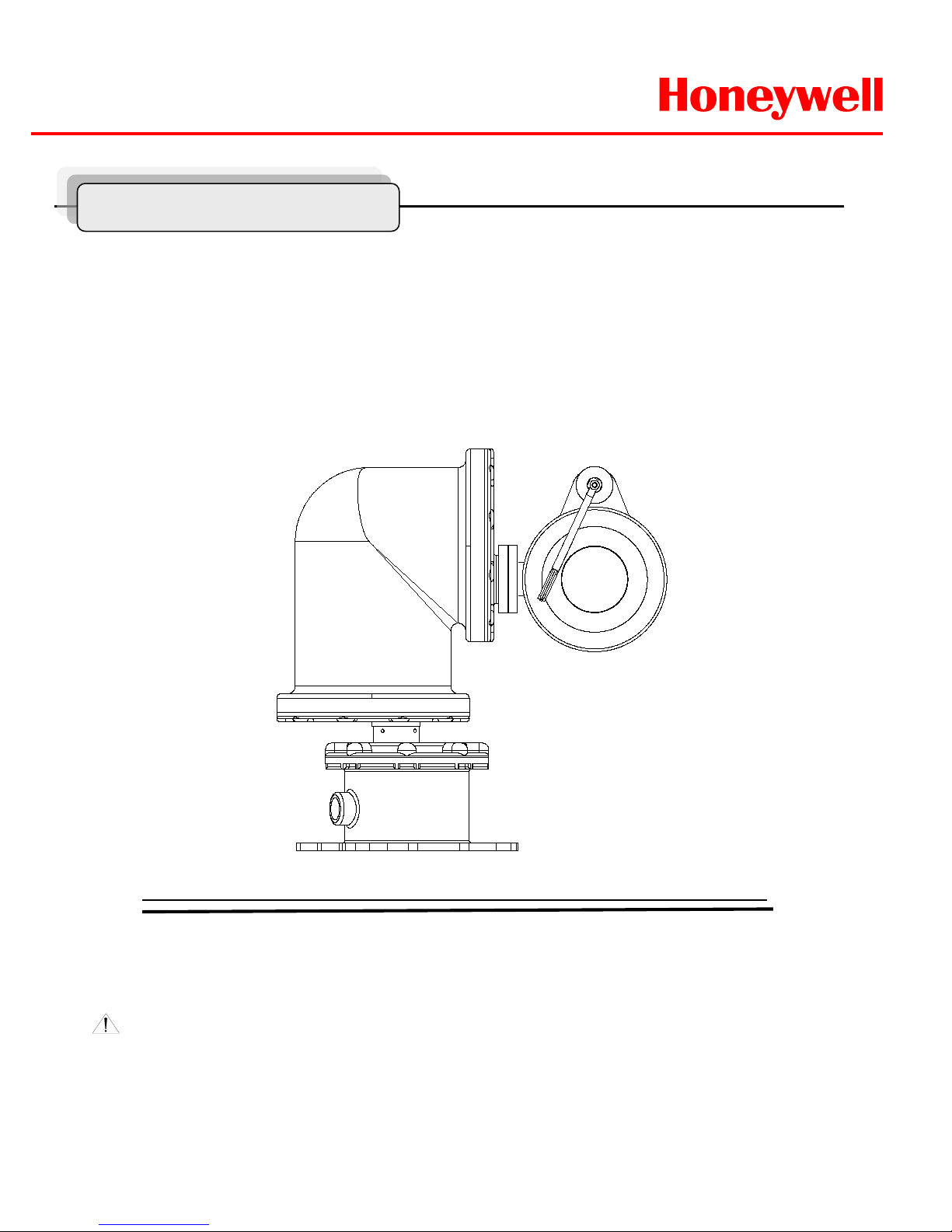
This system can be installed in a standard as b elow Figure1.
If you wish to install another method, you must do it after discussing with a
manufacture.aas
Figure1.
Standard Method of Installation
Page 5
HWLKS-C-M-1918
Honeywell
- 5 -
Methods of Installation
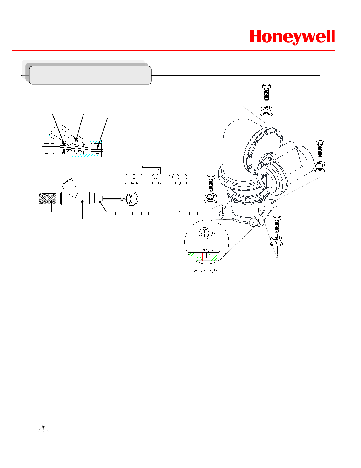
PT 3/4 “-14
Seal Fitting
Explosion proof
Flexible conduit
PT 3/4”-14 Nipple
Fiber Filler
Sealing
compound
Cables
Sealing Method
Standard Method of Installation
To install this system, please refer to Figure2 and do the following steps.
1. Fix this system with M10 x L40mm stainless steel bolts, flat washers and spring washers with at
least four parts each.
2. Make sure the seal fittings and the threaded hole of this system are free of the dirt and particles..
3. Assemble Nipple, the threaded hole of this system, seal fitting and flexible conduit to be fasten
firmly and then the cables must be passed through the seal fitting, Nipple and flexible conduit.
Plus, the sealing fitting, flexible conduit, Nipple should be acquired IECEx Certification.
4. Pack the seal fitting with fiber as the sealing
method of Figure2,
Fiber filler makes a dam that keeps the sealing compound in chamber of the seal fitting while it
cures and hardens. And Pour the sealing compound into the fitting.
5. Install the Earth Cable like Figure2.
WARNING: Keep assembly tightly closed when operating.
Figure2.
Page 6
HWLKS-C-M-1918
Honeywell
- 6 -
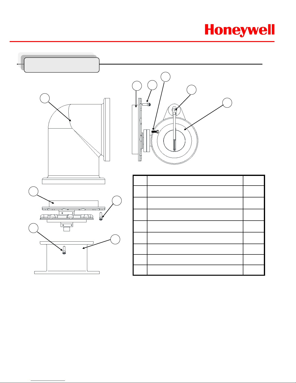
Maintenance
No. Description Q’TY
1 Camera Housing Assy 1EA
2 Tilt Drive Assy 1EA
3 Elbow Housing 1EA
4 Pan Drive Assy 1EA
5 Base Housing 1EA
6 Hexagon Socket Head Cap Screws 28EA
7 Hexagon Head Screws 4EA
8 Hexagon Socket Head Screws 1EA
2
5
4
3
1
7
6
6
To disassembly this product, please refer to Figure3 and do the following steps.
1. Use a Φ5 Wrench for loosen 28EA Hexagon socket head screws.
2. The Torque of jointing screws is approximately 160~200 kgf.cm . Therefore consider the torque when the
screws are loosen.
3. If there is any problem to disassemble or assemble, you should discuss with the specialist or Engineering
site of the product.
Figure3.
8
6
Page 7

HWLKS-C-M-1918
Honeywell
- 7 -
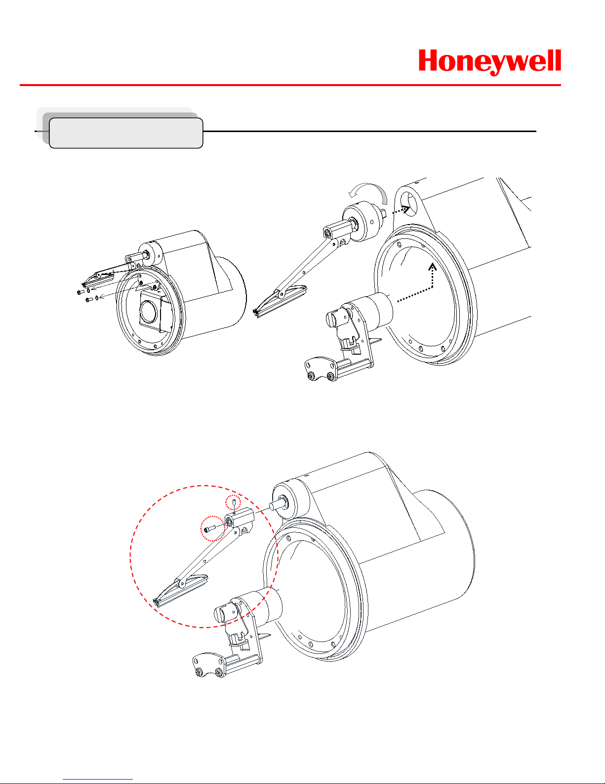
1. Make the wiper vertical
and depart the clamp.
2. Depart the cover with
twist.
3. Loosen the two screws from housing and put out the camera bracket and loosen other
screws to depart the camera, bracket and PCB,
Maintenance
Page 8
HWLKS-C-M-1918
Honeywell
- 8 -
1. Loosen the two screws on the bracket.
2. Loosen the Wiper Head and depart
the wiper motor assembly.
2. Loosen the Hexagon socket head screws and depart the wiper bar from the wiper head.
It can be changed as the expendable supplies.
Maintenance
Page 9
HWLKS-C-M-1918
Honeywell
- 9 -
Figure4.
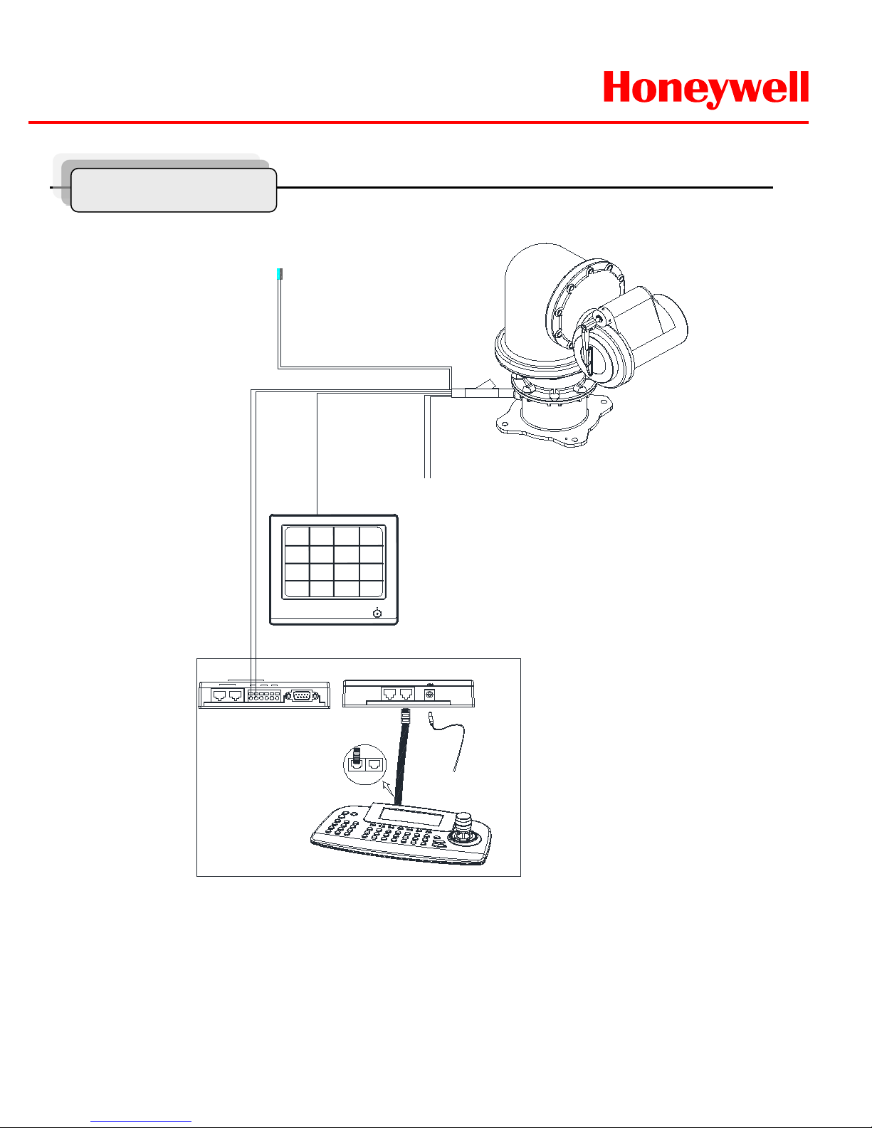
Base Schematic of Installation
Figure4 is recommended for the base Schematic of Installation.
If you wish to consist of another method or other components, you must proceed to do after conferring
with a manufacture.
Base Schematic
POWER
AC100~ 240V
BNC
MAIN MONITOR
DATA1 DATA2
+ - -+ + -
J-BOX REAR
J-BOX FRONT
KEYBOARD CONTROLLER
HTX-5000
REAR
DATA 2 DATA 1
DC 12V
RS 485
1 DOME 2
IN
OUT
DVR
RS 232C
ALARM/DVR
DC 12V
SLAVE
RS 485
+
-
Alram out
COM
N/O
RS 485
Page 10
HWLKS-C-M-1918
Honeywell
- 10 -
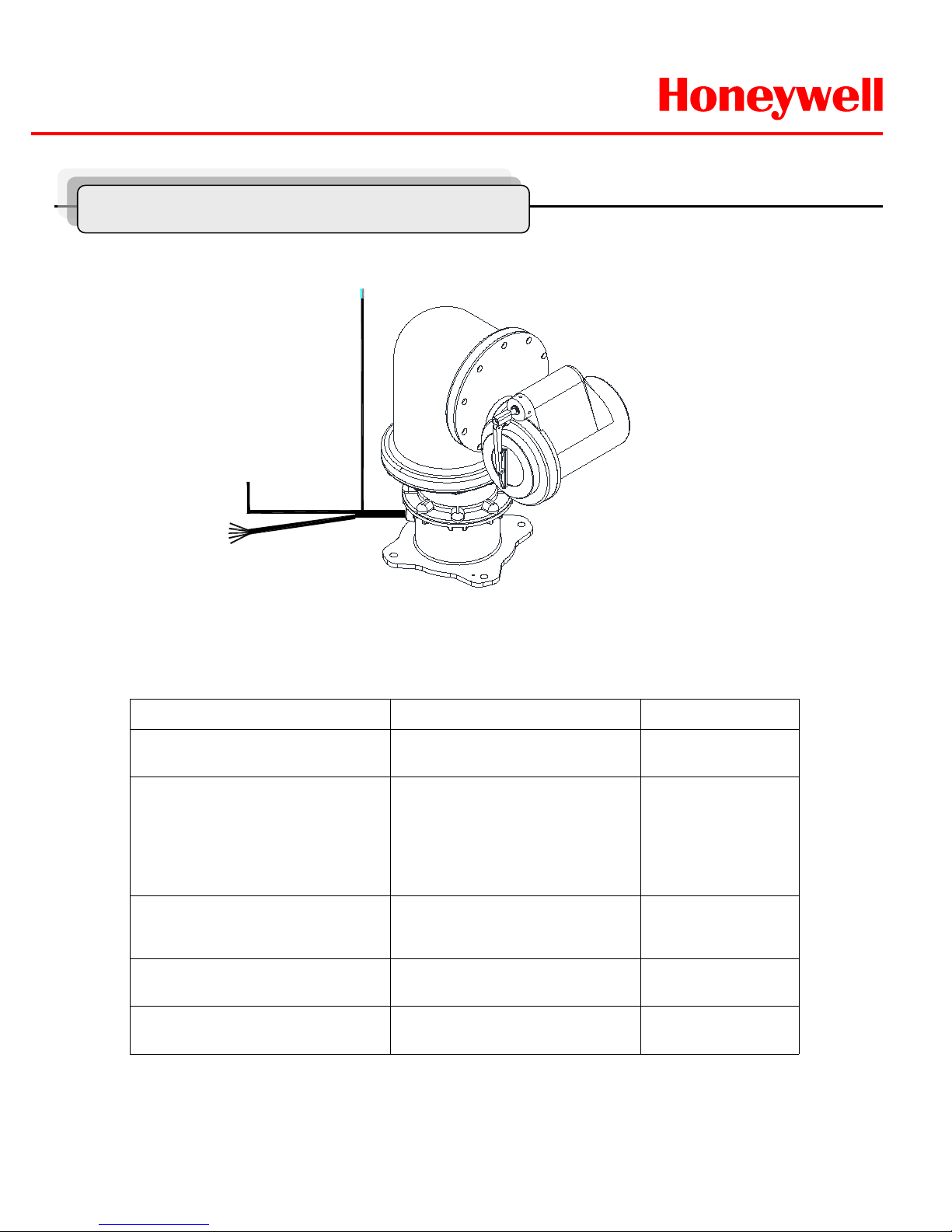
Configuration of Wire Harness
Wire Color Function Description
Brown
SkyBlue
Power Input
(AC 100V ~ 240V)
Hi
Low
Red
Orange
Yellow
Green
Black
Alarm Input
Alarm 1
Alarm 2
Alarm 3
Alarm 4
GND
White
Violet
Blue
Alarm Output
NO
NC
Com
Black
(Coaxial cable)
Video BNC Cable
Blue stripe
White stripe
Control Data
RS485 Data +
RS485 Data -
POWER
AC 100V ~ 240V
BNC
ALARM & DATA
Wire and Power Connection Guide
Page 11
HWLKS-C-M-1918
Honeywell
- 11 -
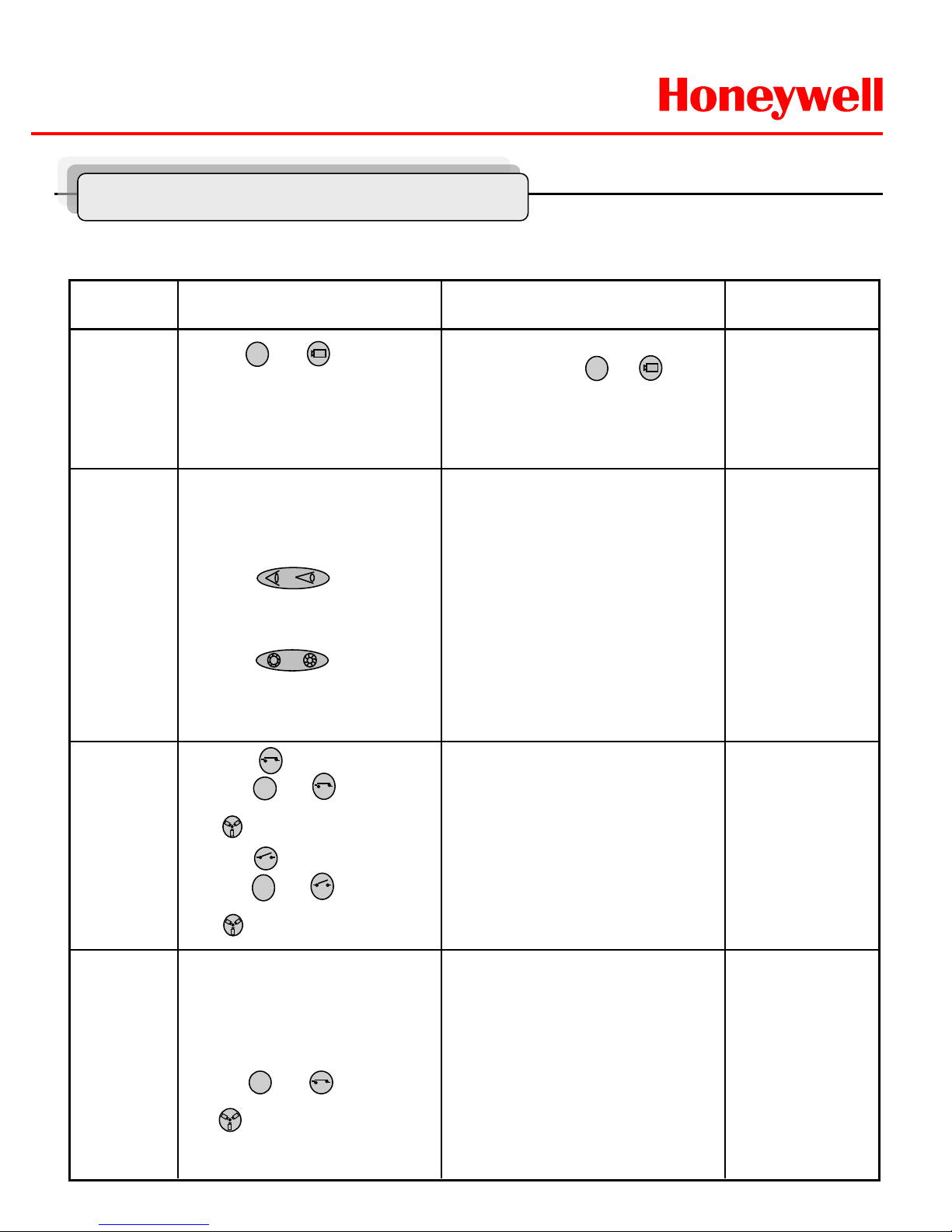
Remarks Results Process Function
Overrides auto
focus
Overrides auto
iris
-ZOOM IN
-ZOOM OUT
-Focus is changed to Near or Far
-Return to Auto Focus mode by
moving the joystick.
-Iris is opened or closed
-Moving the joystick reactivates Auto
Iris mode
ZOOM
/FOCUS/
Iris
To matching ID 01 of 01~99.
If ID set 02, press and (Cam)
button
You can see the moving as following
the direction.
①Press and (CAM) button
in sequence.
② Move Joystick to the right,
left, up and down.
PAN/TILT
1
① Twist Joystick to the right.
② Twist Joystick to the left.
③ Press button.
④ Press button.
2
Forbid to keep the
moving status over
1 hour continually.
-Wiper moves as keeping a steady
angle.
-Wiper stops.
Wiper
Control
① Press (On) button or
Press and (On) button
in sequence.
(86+ Preset) at Pelco Protocol
② Press (Off) button or
Press and (Off) button
in sequence.
(79+ Preset) at Pelco Protocol
2
2
Only in full screen
mode.
Water jet
(Optional)
① Set washing position
-.Move the window face to nozzle
by using pan/tile and save the
position on preset 59.
② Press and button.
(88+ Preset) at Pelco Protocol
- Set the specific position to wash
front window toward the nozzle on
preset 59.
-
Run washing and wiping.
4
Check water level in
the tank
periodically.
Simple Function Control Guide
* This function is specialized to HT X-5000 keyboard.
Page 12

HWLKS-C-M-1918
Honeywell
- 12 -
Remarks Results Process Function
-Menu screen is displayed.
-Go into the sub-menu items.
Change value.
Navigate through the menu items
-Navigate through the menu items.
-Escape from the menu.
Menu
① Press (Menu) button.
(95+ Preset) at Pelco Protocol
② Move Joystick to the right
or left.
③ Move Joystick Up or Down.
④ Press (Menu) or (Esc)
or (Enter) button twice.
ESC
(Esc)
= (96+ Preset)
at Pelco protocol
Scan
① Press (Scan) button.
(60+ Preset) at Pelco Protocol
② Press (Esc) button or move
Joystick to the right or left.
-PTZ goes to Preset1.
-PTZ goes to Preset2.
-PTZ goes to Preset3.
-PTZ goes to Preset4.
① Input Alarm 1
② Input Alarm 2
③ Input Alarm 3
④ Input Alarm 4
Alarm
-PTZ moves to the position which you
have saved the preset.
① Set Preset (direct)
-.Select one button of ~ , ,
(128) and Press (Shift) and
(Preset) in sequence.
②Running Preset
-.Press Number button and
in sequence.
Preset
-PTZ continually moves between the
start and end point which user set
among the preset.
-Escape from the moving Auto Pan.
ESC
Maximum Input
Capacity: 4EA
-.See 22 page for
Detail.
1
1
2
8
Tour
① Press (Tour) button.
(70+ Preset) at Pelco Protocol
② Press (Esc) button or move
Joystick to the right or left.
ESC
1~59+ Preset to
operate
Preset1~59 at Pelco
protocol.
-.See 17 page for
Detail.
-PTZ continually moves to user set
position of the presets.
-Escape from the moving Tour.
61~68+ Preset
to operate Scan1~8
at Pelco protocol.
-.See 19 page for
Detail
71~74+ Preset to
operate Tour1~4 at
Pelco protocol.
-.See 20 page for
Detail.
Simple Function Control Guide
Page 13
HWLKS-C-M-1918
Honeywell
- 13 -
Camera ID Selection
Before you start programming or operating a camera, you should make the camera be under
control of the joystick controller. In other words, the dome camera that you want to effect
changes must be currently selected.
Example: Pressing 1 , 6 and CAM key sequentially will select dome camera 16.
The selected dome camera ID will be displayed on the monitor.
Principle of joystick usage in the programming (editing) mode
Delete value or name of the field.
Home or Off button
Escape from the menu without change.
ESC
PTZ control mode.
SHFT + Joystick
Change value.(Increase / Decrease)
Enter editing title mode.
Zoom handle twist
Finish editing title.
Joystick down
Navigate through the menu items.
Joystick up or down
Go into the sub-menu items.
Execute the command(exit)
Change value.
Navigate through the menu items.
Joystick left or right
Function Button or Joystick movement in menu
1. FUNCTION
Pressing the MENU button on the keyboard controller, the following On-screen MAIN MENU will be
shown on your monitor screen.
MAIN MENU
FUNCTION
ALARM
SCREEN
CAMERA
SETUP
PASSWORD
COMMUNICATION
EXIT MENU
Program and Operation
Page 14
HWLKS-C-M-1918
Honeywell
- 14 -
FUNCTION : Tour/ Preset/ AutoScan
NUMBER : - - TIME : 10~240 Seconds
OPERATION : ENABLE/ DISABLE
The HOME function invokes predefined functions such as Preset, Tour, Pattern, or Scan function after
the keyboard controller has been idle for a programmed time.
Follow the steps below to program the Home function:
1.
Select the camera number by pressing No. and CAM
2.Press MENU to display the main menu on the monitor.
3.Push the Joystick to the right on “FUNCTION”.
4.Enter Home Function menu by pushing the Joystick to the right.
5.Push the Joystick to the right/ left (or twist CCW/CW) to scroll Tour, Auto Scan and Preset
functions.
6.Select Function Number by pushing the Joystick down, and twist the Joystick to the
CCW/CW (or push right/left). The executable function number w il l be scrolled. If selected
function is not programmed, it won’t change. Go to setup function first.
Locate the cursor on the FUNCTION item and then push the joystick to the right to enter
FUNCTION menu.
FUNCTION
HOME FUNCTION
PRESET
SCAN
TOUR
EXIT MENU
1.1 HOME FUNCTION ( MENU =>FUNCTION => HOME FUNCTION)
After HOME FUNCTION item has been selected, follow the di r ect ions below to set
HOME function.
HOME FUNCTION
FUNCTION : TOUR
NUMBER : --TIME : 060 SEC
OPERATION : DISABLE
SAVE AND EXIT
Program and Operation
Page 15

HWLKS-C-M-1918
Honeywell
- 15 -
7.Pushing the Joystick down and twist the Joystick to CCW/CW (or push the stick to
right/left) to set waiting time.
8. Locate the cursor on OPERATION option by pushing the Joystick down. Choose
operation status Enable or Disable by pushing the Joystick to the right or to the
left (or twist CCW/CW).
1.2 PRESET ( MENU => FUNCTION => PRESET, Short Cut :PRST )
Preset memorizes pan, tilt, zoom, focus and iris settings. Once programmed, pressing combination of
0 ~9 numbers and a Preset button on your controller automatically calls up the preset position.
Presets may be assigned to alarm actions or as the “home” position for the dome camera.
Locate the cursor on the PRESET item and then push the joystick to the right to enter PRESET
menu.
FUNCTION
HOME FUNCTION
PRESET
SCAN
TOUR
EXIT MENU
There are 16 pages of preset programming menu. Each page can hold 8 presets. Locate the cursor
on “
PREV NEXT”, preset menu pages can be scrolled by pushing the Joystick to the Left or
Right on the “
PREV NEXT”.
PRESET 01/16
NO. F I B W TITLE
001 A A F X xxxxxxxxxxxxxxxx
002 M M O X ---------------003 - - - ---------------004 - - - ---------------005 - - - ---------------006 - - - ---------------007 - - - ---------------008 - - - ---------------PREV NEXT
SAVE AND EXIT
F : FOCUS I : IRIS B : BLC W : WDR
X : 16 digit of preset title
- : not defined
█ : Current cursor position
F : A(Auto Tracking )/M(Manual Tracking)
I : A(Auto Iris)/M(Manual Iris)
B : F(BLC OFF)/O(BLC ON)/A(Auto BLC)/B(BMB)
W : O(on) / X(Off)
Program and Operation
Page 16

HWLKS-C-M-1918
Honeywell
- 16 -
Follow the steps below to program the Preset positions.
1.
Select the camera number by pressing 0 ~9 and CAM.
2. Simply press PRST button to enter preset menu. ( MENU => FUNCTION => PRESET)
3. Select the empty preset location to be programmed using the Joystick up/down. If selected
location is not empty, pressing PRST button will show your predefined position.
4. After selecting an empty position, press and hold SHFT/PGM then use the Joystick to control
the direction of the camera and lens.(Or twist zoom handle or hit zoom button to start PTZ
control for view selection.)
5. After aiming the camera (view direction and lens control) at specific position, release
SHFT/PGM button (or hit the focus button). The selected location No. field will be filled with “A
A F”. Push the joystick to the right to select each Focus/ Iris /BLC mode using zoom handle.
6. Move the cursor to the title field to edit/enter the title. Rotate the handle CW and CCW to scroll
through the alphanumeric characters. Push the handle to right or left to select next or previous
digit.
7. To finish entering the title, push the Joystick up/downward.
8. Locate the cursor on “PREV NEXT” item to select the previous/next page of presets, scroll the
page by pushing the Joystick to the Left on “PREV NEXT”.
9. Repeat steps 2 through 8 for each additional preset position.
10. Select Save and Exit by pushing the Joystick to the right. Press ESC to exit the Preset menu
without saving
11. Press the HOME or OFF button to delete programmed data.
NOTE: Press the Home or OFF button at programmed position to delete a programmed preset
view.
Shortcut of Preset Program.
Select direction of the camera, zoom and focus to be programmed, then press No. (1~128), and then
press SHFT, PRST subsequently. The current view will be stored to the selected preset number
if position is empty. If selected preset number is not empty, “PRESET EXISTING” message will
be displayed on the monitor and you will be prompted to overwrite.
Example: 1, 0 + PGM + PRST will memorize current view as preset No. 10. In this case, focus and
Iris mode will be memorized as auto and dwell time will be set to 3 sec.
Program and Operation
Page 17

HWLKS-C-M-1918
Honeywell
- 17 -
1.3 SCAN ( MENU => FUNCTION => SCAN or Shortcut: SCAN)
SCAN MENU 01/08
SCAN 01 : AUTOSCAN01
SPEED : 1~8/SLW/MID
START : 127.1, 027.0 zoom
END : 157.7, 080.7 zoom
DIR. : CCW (PAN:000.0)
SWAP : OFF
SAVE AND EXIT
Follow the steps below to program Scans.
1.Press the SCAN key to enter Auto Scan menu directly. (or MENU => FUNCTION => SCAN).
2.Select an Auto Scan number by pushing the Joystick left or right.
3.Twist the Joystick to enter the title by scrolling through the alphanumeric characters and
pushing the handle to the right or left to move to the next space. Press
ENTR key or push the
Joystick down to finish title mode.
4.Push the Joystick dow nward to select “SPEED” and set the speed by twisting the Joystick
clockwise or counterclockwise or moving the
Joystick left/ right to select the auto scan speed.
5.When finish entering the title, select “START ANGLE” with the Joystick. Hold down the
SHFT/PGM key while selecting the start position using the Joystick. Current panning position will
be displayed. Release
SHFT/PGM key to complete the selection of the start position. (Or twist zoom
handle or hit zoom button to start PTZ control for view selection and hit the Focus button to stop.)
6.Push the Joystick downward to select “END ANGLE.” Hold down the SHFT/PGM key w hi le
moving the Joystick to select the end position. The end position angle should be larger than start
position. Release the
SHFT/PGM key to complete the selection of the end position. (Or twist
zoom handle or hit zoom button to start PTZ control for view selection and hit the Focus button to
stop.)
7.Push the Joystick dow nward to select “DIR.” Set the scan direction by moving the Joystick
left and right to select the auto scan direction.(CW or CCW)
SCAN01:AUTOSCAN01 ~ SCAN08:AUTOSCAN08
SPEED(M OD E) : 1/ 2 / 3/ 4/ 5/ 6/ 7/ 8/ SLOW / MEDIUM
1: SLOWER ↔ 8 FASTER
SLW : smooth Diagonal Scan in slowest speed
MID : smooth Diagonal Scan in medium speed
Diagonal Scan shows moving path from start point to
end point including tilt and zoom simultaneously.
The Scan function supports up to 16 programmed section of angles at 8 programmable speeds
.
Program and Operation
Page 18

HWLKS-C-M-1918
Honeywell
- 18 -
8. Push the Joystick downward to select “SWAP” and set the swap by moving the Joystick
left and right to select the swap ON or OFF.
9. Select Save and Exit by pushing the Joystick to the right. Press ESC to exit the program
without saving.
10. Press the HOME or OFF button to delete programmed data
NOTE: Press 17 + SCAN to automatically calls up the auto-pan function.
TOUR 01:xxxxxxxxxxxx 01/04
FUNC NO S DW TITLE
PRST 001 S 99 ---------------SCAN 016 S 99 ---------------TOUR 008 S 99 ----------------
---- --- - -- ----------------
---- --- - -- ----------------
---- --- - -- ----------------
---- --- - -- ---------------PREV NEXT
SAVE AND EXIT
xxxxx : 16 digits of title for tour label
- - - : blank preset position
Speed : Fast (Normal)/ Slow V
. Scan/ Medium V. Scan
DWell : 01-99 Sec
PRST : Preset 1~128
SCAN : SCAN 1~8
TOUR : TOUR 2~4
1.4 TOUR (or ME NU => FUNCTION => TOUR, Short Cut: TOUR)
There are 8 programmable Tours. Each Tour consists of up to 64 Preset positions,
Scans or other Tours. Using second-level Tours, it can be expanded to over 56 functions in a
single Tour. However tours second level Tours will be ignored when called by a Tours. This
can be best illustrated by the following example:
If Tour 01 : Preset 02, Preset 03,Tour 02, Tour 03
Tour 02 : Preset 05, Preset 06, Tour 04, Preset 05
Tour 03 : Preset 07,
Tour 04 : Preset 08. Preset 05,
Tour01 executes as follows:
Preset 02 Preset 03 Preset 05 Preset 06 Preset 05 Preset 07 ...
(Repeat) ---Tour 04 in Tour 02 will be skipped in Tour 01
Tour02 executes as follows:
Preset 05 Preset 06 Preset 08 Preset 05 …(Repeat) (Tour4 is still valid if
called directly from Tour2.)
Program and Operation
Page 19

HWLKS-C-M-1918
Honeywell
- 19 -
Follow the steps below to program the Tours:
1.
Press MENU => FUNCTION => TOUR, Short Cut: TOUR MENU to display the main menu on
the monitor.
No. + SHFT+TOUR will open directly Tour No.
2. Choose an empty location of function by pushing the
Joystick up or down.
3. Stored Preset view can be recalled by pressing
Prst button, the camera will move to the stored
Preset view.
4. To place predefined functions as a Tour, press the function buttons (such as Tour or Scan ,Prst
). Then select function No. by twisting the Zoom handle. (Programmed function No. will be
scrolled). To remove functions from the Tour, press the HOME or Off button, blank position mark
(- - -) wi ll be displayed. You can overwrite the programmed position.
5. Repeat Step 2 through 4 for each desired position. Each title will be displayed on top of the line.
6. Up to 8 Presets, Tours, Patterns Scans can be selected for a Tour. You can expand the Tour
sequence by calling other programmed tours . Push the
Joystick handle to right or left while
the cursor is on the top of the line (TOUR 01) to select another page of the Tour menu. (TOUR
01)
7. You can enter a title for the selected Tour by twisting the Joystick while the cursor is on the top
of the line (TOUR 01). Rotate the handle clockwise or counterclockwise to scroll through the
alphanumeric characters. Push the handle to the right or left to select the next or previous digit.
8. Select Save and Exit by pushing the Joystick to the right. Press ESC to exit the program
without saving.
9. Press the HOME or OFF button to delete programmed data.
NOTE: All functions should be programmed before being referred to in the tour menu. Otherwise
functions won’t be selectable by item 4 in the procedure.
Program and Operation
Page 20

HWLKS-C-M-1918
Honeywell
- 20 -
2. ALARM ( MENU => ALARM)
Locate the cursor on ALARM item in the main menu and push the joy s ti ck to the ri g ht for
ALARM programming of the camera.
ALARM SETUP
NO FUN PRI IN OUT HLD LATCH
01 001 0 OFF OFF 001 OFF
02 002 4 OFF OFF 001 OFF
03 003 4 OFF OFF 001 OFF
04 004 3 OFF OFF 001 OFF
SAVE AND EXIT
NO : Alarm input number
FUNC : Priority 1~4 calls Preset(xxx),
Priority 0 supports dedicated functions like a Preset.
PRI : Lower No. has higher priority, Equal priority alarms will be serviced repeatedly.
IN : NO/NC - normally open /Closed, OFF - ignore
OUT : RO1 - Relay out 1 OFF - No output.
HLD : Alarm will be held for programmed time (01 to 255 seconds)
LATCH : ON - Shows all alarms including past alarm, OFF - Shows activated alarms only.
There are 4 levels of priority. 0 : Highest priority supports repeated/dedicated functions like a Preset.
1~4: Same level of alarm calls presets one after the other.
Ex) Alarm 01 calls Preset 01, After alarm 01 is released alarm 02, 03 will call preset 48 and preset 01
MAIN MENU
FUNCTION
ALARM
SCREEN
CAMERA
SETUP
PASSWORD
COMMUNICATION
EXIT MENU
Program and Operation
Page 21

HWLKS-C-M-1918
Honeywell
- 21 -
1. Press Menu to display the main menu on the monitor. Select the Alarm option by pushing the
Joystick up or down and push to right to enter the detail menu.
2. Select the alarm input number by pushing the Joystick up or down and select the column you
wish to setup. Selected position will be highlighted.
3. Select the Preset, Status of Input (NC/NO/OFF), and Output (RO1/OFF) by pushing the
Joystick to the right or to the left.
4. To increase or decrease the preset number or to change the status or output number, twist the
Joystick clockwise or counterclockwise. In case of preset, programmed preset number will be
scrolled.
5. Locate the cursor on Save and exit and push the Joystick to the Save and exit.
Press ESC to exit the program without saving.
3. SCREEN ( MENU => SCREEN)
Pressing the MENU button on the keyboard controller, the following On-screen MAIN MENU
will be shown on your monitor screen.
Locate the cursor on the SCREEN item and then push the joystick to the right to enter SCREEN
menu.
SCREEN MENU
LANGUAGE
PRIVACY ZONE
NORTH DIRECTION : 000.0
ZONE TITLE
CAMERA TITLE : EXPTZ
OSD DISPLAY
SAVE AND EXIT
MAIN MENU
FUNCTION
ALARM
SCREEN
CAMERA
SETUP
PASSWORD
COMMUNICATION
EXIT MENU
Program and Operation
Page 22

HWLKS-C-M-1918
Honeywell
- 22 -
3.1 LANGUAGE( MENU => SCREEN => LANGUAGE)
Current, Language supports the only English.
3.2 PRIVACY ZONE ( MENU => SCREEN => PRIVACY ZONE)
Locate the cursor on the PRIVACY ZONE item and then push the joystick to the right to enter
the menu.
This function disables the viewing of restricted areas for privacy reasons. Mask up to 8 unwanted
views in a camera.
PRIVACY ZONE SETUP
NO TITLE METHOD
01 xxxxxxxxxxxxxxxx ON MASK
02 xxxxxxxxxxxxxxxx OFF V.OFF
03 OFF ---04 OFF ---05 OFF ---06 OFF ---07 OFF ---08 OFF ---COLOR : BLUE
SAVE AND EXIT
SCREEN MENU
LANGUAGE
PRIVACY ZONE
NORTH DIRECTION :000.0
ZONE TITLE
CAMERA TITLE : EXPTZ
OSD DISPLAY
SAVE AND EXIT
Program and Operation
COLOR : BLUE/GREEN/YELLOW/CYAN/MAGENTA/BLACK/GRAY/D.GRAY/WHITE/RED
Page 23

HWLKS-C-M-1918
Honeywell
- 23 -
1. Select the Privacy Zone option by pushing Joystick Up or Down and push to right to enter
the detail menu.
2. Select the privacy zone number by pushing the Joystick up or down.
3. To enter the zone name, rotate the handle clockwise or counterclockwise. You can select
alphanumeric characters by rotating the handle. Move to the next character position by
pushing the Joystick to the right. To finish entering the title, push the Joystick down or
press the ENTER key.
4. To adjust the “marked” (privacy) area, press and hold down the SHFT/PGM key and then
use the Joystick (direction and zoom) until you get desired view. Release the key, the right
column will be set to ON. (Or twist zoom handle or hit zoom button to start PTZ control for
view selection and hit the Focus button to exit from control mode.)
5. You can overwrite an existing zone. Use the Home key to delete the marked zone, or push
the Joystick to the right or left to turn the stored zone On or Off.
6. Select the mask color by pushing the Joystick left or right
7. Select the Save and Exit option by pushing the Joystick up or down. Save and exit the
program by pushing the Joystick to the right. Press ESC to exit the program without saving.
Press the HOME or OFF button to delete programmed privacy zone.
Program and Operation
Page 24

HWLKS-C-M-1918
Honeywell
- 24 -
3.3 NORTH DIRECTION ( MENU => SCREEN => NORTH DIRECTION)
Program and Operation
Push the joystick handle to the right to select NORTH DIRECTION options
1. Move to POSITION item to set north direction, press and down the SHFT/PGM key and then
use the Joystick (direction and zoom) until you get desired direction. Release the key then
current pan angle will be displayed on position item. (Or twist zoom handle or hit zoom button
to start PTZ control for view selection and hit the Focus button to exit from control mode.)
3.4 ZONE TITLE ( MENU => SCREEN => ZONE TITLE)
Enter a specific name in sectioned angle between START and END.
ZONE TITLE 01/03
NO TITLE START END
01 WINDOW 123.4 345.6
02 ----- ----03 ----- ----04 ----- ----05 ----- ----06 ----- ----PREV NEXT
SAVE AND EXIT
SCREEN MENU
LANGUAGE
PRIVACY ZONE
NORTH DIRECTION :000.0
ZONE TITLE
CAMERA TITLE : EXPTZ
OSD DISPLAY
SAVE AND EXIT
Page 25

HWLKS-C-M-1918
Honeywell
- 25 -
Program and Operation
1. Press MENU => SCREEN => ZONE TITLE to display zone title menu on the monitor.
2. Select the zone number by pushing the Joystick up or down. Select Start, End or number
column to be set by pushing the handle to the right or left. The selected column will be
highlighted.
3. Twist the joystick handle on the No. column to enter zone title. You can select alphanumeric
characters by rotating the handle. Move to the next character by pushing the Joystick to the
right. To finish entering the title, push the Joystick down.
4. To adjust panning limit, press the SHFT/PGM key and hold down. Then use the Joystick to go
the desired direction. The end limit must be in an increasing direction. (Start < End). (Or twist
zoom handle or hit zoom button to start PTZ control for view selection and hit the Focus button
to exit from control mode.)
5. PREV NEXT : got to previous page or next page of the menu
6. Save and exit the program by pushing the Joystick to the right. Press ESC to exit the program
without saving.
7. Press the HOME or OFF button to delete programmed data.
3.5 CAMERA TITLE ( MENU => SCREEN => CAMERA TITLE )
Push the joystick handle to the right to select CAMERA TITLE options
1. Move the joystick handle right. You can select alphanumeric characters by rotating the handle.
Move to the next character by pushing the Joystick to the right. Camera title is limited to 8
characters (A~Z, 0~9).
2.
To finish entering the title, push the Joystick down.
3. Save and exit with joystick handle to right ( Or ESC to exit without saving)
SCREEN MENU
LANGUAGE
PRIVACY ZONE
NORTH DIRECTION :000.0
ZONE TITLE
CAMERA TITLE : EXPTZ
OSD DISPLAY
SAVE AND EXIT
Page 26

HWLKS-C-M-1918
Honeywell
- 26 -
Program and Operation
3.6 OSD DISPLAY ( MENU => SCREEN => OSD DISPLAY)
Push the joystick handle to the right to select OSD DISPLAY options
SCREEN MENU
LANGUAGE
PRIVACY ZONE
NORTH DIRECTION :000.0
ZONE TITLE
CAMERA TITLE : EXPTZ
OSD DISPLAY
SAVE AND EXIT
1.
Move the joystick handle right. You can select OSD DISPLAY ON/OFF each functions.
2. Save and exit with joystick handle to right ( Or ESC to exit without saving)
OSD DISPLAY
FUNCTION TITLE : ON
CAMERA TITLE : ON
ZONE TITLE : ON
NORTH DIRECTION : OFF
CAMERA POSITION : ON
CAMERA ID : ON
ZOOM MAGNIFICATION : OFF
SAVE AND EXIT
Page 27

HWLKS-C-M-1918
Honeywell
- 27 -
Program and Operation
4. CAMERA ( MENU => CAMERA)
NOTE: The menu features will vary depending on the camera module installed in your
EXPTZ camera.
CAMERA MENU
FOCUS CONTROL : AUTO / MANUAL
WB CONTROL
AE CONTROL
BLC SETUP
SHARPNESS : 10
DIGITAL ZOOM
NIGHT SHOT
CAMERA DEFAULT
SAVE AND EXIT
4.1 FOCUS CONTROL( MENU => CAMERA => FOCUS CONTROL)
CAUTION: Avoid continuous, 24-hour use of the auto focus heavy movement condition. This will
shorten the lifespan of the lens.
4.2 WB (white balance) ( MENU => CAMERA => WB CONTROL)
WB SETUP
MODE : ATW
R.GAIN : AUTO
B.GAIN : AUTO
EXIT MENU
MODE: ATW / INDOOR / OUTDOOR / M WB /
AWC(LOCK) / AWC(AUTO)
R.GAIN/B.GAIN: 0~255 (MWB)
Use the ATW mode for normal use.
Push the Joystick to the right or left to change.
1.
Move the joystick handle right. You can select FOCUS CONTROL AUTO / MANUAL.
2. Save and exit with joystick handle to right ( Or ESC to exit without saving)
Page 28

HWLKS-C-M-1918
Honeywell
- 28 -
4.3 AE CONTROL ( MENU => CAMERA => AE CONTROL)
Program and Operation
Depending on your dome camera, you will see either the following screen or the next.
AE SETUP
MODE : FULL AUTO
SLOW SHUTTER : x10
IRIS : Auto
GAIN : Auto
BRIGHT : 008
SHUTTER : Normal
MAX GAIN : 30DB
DNR : OFF
EXIT MENU
MODE : FULL AUTO / SHU TTER FIX / IRIS FIX / AGC FIX / M A NU AL
SLOW SHUTTER : OFF / X1~X18 / X20 / X40 / X80 / X160 / X320 / X512
IRIS : CLOSE / F16/ F11 / F8.0 / F7.6 / F5.6 / F4.2 / F4.0 / F2.8 / F2.0 /
F1.8 / OPEN
GAIN : OFF / 8 DB / 10 DB / …… / 36 DB / AUTO
BRIGHT : 000 ~ 015 / NORMAL (008: Default)
SHUTTER : 1/60(1/50), 1/100(1/120),1/250, 1/500, 1/1000, 1/2000, 1/4000,
1/10000, 1/20000, 1/50000. 1/100000
MAX GAIN : OFF / 8DB / 10DB / … / 36DB
DNR : OFF / LOW / HIGH
NOTE : Values in ( ) are for PAL Camera.
Page 29

HWLKS-C-M-1918
Honeywell
- 29 -
4.4 BLC SETUP ( MENU CAMERA BLC SETUP)
Program and Operation
Objects in front of bright backgrounds will be clearer with BLC ON/AUTO/BMB.
*) BMB [Black Mask BLC] : It is another function of BLC. It mask the excessive light to dark level and
make brighter to see object around the excessive light.
BLC SETUP
BLC : OFF
BLOCK SET
BLOCK PREVIEW
LEVEL : 07
EXIT MENU
BLC : OFF / ON / AUTO / WDR / BM B
LEVEL : 01 ~ 20
(As BMB level lower, BMB masked range enlarge more and more)
Select BMB operated area depending on circumstance, for using BMB more effectively.
Screen is divided 16 areas, each area is set separately.
BLC SETUP
BLC : BMB
BLOCK SET
1 2 3 4
01 - - - 02 - * * 03 - * * 04 - - - SET→FAR/NEAR,EXIT→ESC
SELECT→TELE/WIDE
PREVIEW→OPEN/CLOSE
4.5 SHARPNESS CONTROL ( MENU => CAMERA =>SHAPENESS)
The higher, the more enhanced edges in the picture. : 0~15
Page 30

HWLKS-C-M-1918
Honeywell
- 30 -
Program and Operation
4.6 DIGITAL ZOOM ( MENU => CAMERA =>DIGITAL ZOOM)
MAX : OFF(Optical zoom only) / 2x / 4x / Max(Digitally magnif ies up to 2x, 4x 8x 16x respectively)
PIP(Picture in Picture) : ON / OFF
POSITION : R/BOT / R.TOP / L.BOT / L.TOP
4.7 NIGHT SHOT MENU ( MENU => CAMERA =>NIGHT SHOT)
The NIGHT SHOT option removes the IR Cut filter of the camera and makes the camera
sensitive to near infrared.
If NIGHT SHOT mode of the selected camera is set to Manual, 10+ ON will enable the NIGHT
SHOT mode, 10+ OFF will turn off the NIGHT SHOT mode
NIGHT SHOT SETUP
MODE : AUTO
LOCAL CONTROL : OFF
EXIT MENU
MODE : MANUAL / AUTO
AUTO – Camera automatically goes into B&W mode at low light.
MANUAL - M anually controls the Night Shot mode in LOCAL CONTROL option.
On/Off Night Shot mode remotely by pressing 10+ ON/ 10+ OFF.
4.8 CAMERA DEFAULT ( M ENU => CAMERA =>CAMERA DEFAULT)
Returns all changed camera values to factory default .
CAMERA DEFAULT
ARE YOU SURE ?
YES
NO
YES : ENTER OR MENU KEY
NO : ESC KEY
DIGITAL ZOOM SETUP
MAX : OFF
PIP : ON
POSITION : R.TOP
EXIT MENU
Page 31

HWLKS-C-M-1918
Honeywell
- 31 -
Program and Operation
5. SETUP ( MENU => SETUP)
SETUP MENU
FLIP FUNCTION : ON
P/T SPEED : FAST
PRESET FREEZE : OFF
RESET ORIGIN
FACTORY DEFAULT
ERASE DATA
SYSTEM INFORMATION
SAVE AND EXIT
5.1 FLIP (MENU => SETUP => FLIP)
When the EXPTZ camera is mounted on a somewhere, you can set one of three ways in how it
can track a target moving in a path directly below the camera:
ON - When the camera reaches the floor directly above the moving object, the dome camera
tracks the object smoothly with a digitally corrected image.
OFF – The dome camera does not perform a flip.
5.2 P/T SPEED (MENU => SETUP => SPEED)
User can select preferable speed curves of manual control.( FAST / MID/ SLOW)
5.3 PRESET FREEZE (M ENU => SETUP => PRESET FREEZE)
ON - This option is used to set the pause previous image until the preset action is complete.
OFF – No action
5.4 RESET ORIGIN (MENU => SETUP => PRESET ORIGIN)
This option is used to find and adjust origin position.
Page 32

HWLKS-C-M-1918
Honeywell
- 32 -
Program and Operation
5.5 FA CT ORY DEF A ULT (MENU => SETUP => FA CTORY DEFAULT)
FACTORY DEFAULT
ARE YOU SURE ?
YES
NO
Programmed data go back to initial state as ex-factory
5.6 ERASE DATA (M ENU => SETUP => ERASE DATA )
Erase programmed data in the EEPROM of the selected dome camera. Press MENU or ENTER
button to erase data, ESC key to exit without erasing. Origin offset value is not affected.
CAUTION: Unless you download the data into a safe place, all the data in the selected EXPTZ
camera will be lost. (Refer to Download/ Upload data function in the Keyboard Configuration
utility)
5.9 SYSTEM INFORMATION (MENU => SETUP => SYSTEM INFORMAION)
SYSTEM INFORMATION
CAMERA TYPE : XXXXXXX
H/W VERSION : REV1.1
ROM VERSION : V0.16
PROTOCOL : S2E
BUADRATE : 9600BPS
EXIT MENU
This screen shows information of the EXPTZ camera for service or trouble shooting
YES : ENTER OR MENU KEY
NO : ESC KEY
ERASE PROGRAMMED DATA
ARE YOU SURE ?
YES
NO
YES : ENTER OR MENU KEY
NO : ESC KEY
Page 33

HWLKS-C-M-1918
Honeywell
- 33 -
PASSWORD SETUP
MENU PASSWORD : ON/OFF
CHANGE PASSWORD : ****
CONFIRM : ****
SAVE AND EXIT
6. PASSWORD ( MENU => PASSW ROD)
1. Change password : Move the joystick handle right and up or down to select number
0~9(a number of four figures), and do same way to confirm.
2. Save and exit with joystick handle to right ( Or ESC to exit without saving)
7. COMMUNICATION ( MENU => COMMUNICATION)
COMMUNICATION SETUP
EXPTZ ID : 0001
BAUDRATE : 9600
PROTOCAL : AUTO
SAVE AND EXIT
1.
Move the joystick handle right. You can select CAMERA ID to select the joystick up or down.
2. Move the joystick handle right. You can select BARDRATE (2400/ 4800/ 9600/ 19200/
38400/ 57600/ 115K/ 230K) to select the joystick up or down.
3. Move the joystick handle right. You can select protocol by the joystick up or down.
4. Save and exit with joystick handle to right ( Or ESC to exit without saving)
5. You should use the remote controller which was included to the product to change its
protocol for communicating.
Program and Operation
Page 34

HWLKS-C-M-1918
Honeywell
- 34 -
Mechanical Part
Specifications
Models
Spec
EXPTZ252/363NA EXPTZ252/363PA
Signal System NTSC PAL
Ex. Class Ex d IIC T6 ( IECEx, ATEX, CE, FCC, KC, CCEs )
Front window Ground and polished, fully tempered plate glass
Construction SUS 316
Protection Degree IP 67
Pan & Tilt
Angle: 360° Continuous rotation
Speed: 0.5°~ 60°/sec (Manually, Proportional to Zoom, Vector Scan)
60°/sec Max (Preset)
Wiper Angle Angle : 50°±2˚ movement
Flip Rotate 90° /270° at tilt angle
Scan 8 Scan Selectable
Preset 128 positions with focus, iris, & BLC setting
Tour 4 Tour Selectable
Alarm
Input: 4 Normal dry contacts (Selectable NC/NO)
Output: 1 Normal relays 24VDC/1A max. (Selectable NC/NO)
Control RS-485
Input Voltage 100-240 V~, 50/60Hz
Power consumption 1.0A, 50W
Operating Temperature
-10°C ~ 60°C (Recommend -5°C ~ 50°C )
Weight Approx. 40 kg
Page 35

HWLKS-C-M-1918
Honeywell
- 35 -
Specifications
Optical Part
Models
Spec
EXPTZ252NA EXPTZ252PA EXPTZ252NA EXPTZ252PA
Pick-up Device
1/4" SONY Supper HAD CCD
Total pixels
410,000 pixels
(811(H)x508(V))
470,000 pixels
(795(H)x596(V))
410,000 pixels
(811(H)x508(V))
470,000 pixels
(795(H)x596(V))
Effective pixels
380,000 pixels
(768(H)x494(V))
440,000 pixels
(752(H)x582(V))
380,000 pixels
(768(H)x494(V))
440,000 pixels
(752(H)x582(V))
Television
System
NTSC, 525 Lines, 2:1
Interlace
PAL, 625 Lines, 2:1
Interlace
NTSC, 525 Lines, 2:1
Interlace
PAL, 625 Lines, 2:1
Interlace
Lens
specifications
x25 (f=3.8~95mm), F1.6 (Wide) ~ F3.7 (Tele) x36 (f=3.4 ~ 122.4mm), F1.6 (Wide) ~ F4.5 (Tele)
View of angle
D: 68.8°(wide), 3.0°(tele), H: 56.2°(wide),
2.4°(tele), V: 42.6°(wide), 1.8°(tele)
H: 57.8°(wide), 1.7°(tele), V: 43.7°(wide),
1.3°(tele)
Digital Zoom
OFF ~ x16 Variable ( Total x400) OFF ~ x16 Variable ( Total x576)
Sync. System
Internal
Horizontal
Resolution
More than 520 TV lines
S/N Ratio
More than 50dB (AGC OFF)
Minimum
Illumination
0.5 lx (50 IRE)
0.05 lx (50IRE, IR Filter OFF)
0.001 lx (50IRE, IR Filter ON, 512 Fields)
0.0001 lx (50IRE, IR Filter OFF, 512 Fields)
Digital Slow
Shutter
ON / OFF, (x2 ~ x512 Variable)
Shutter Control
1/60 ~ 1/100,000 1/50 ~ 1/100,000 1/60 ~ 1/100,000 1/50 ~ 1/100,000
White Balance
ATW/INDOOR/OUTDOOR/MANUAL/AWC
BMB Mode
ON/OFF (16 Area Selectable, 5 Color Selectable)
BLC Mode
OFF / BLC / ABLC
WDR Mode
ON /OFF
PIP Mode
ON /OFF
DNR Mode
OFF / LOW / HIGH
QUAD Mode
ON / OFF
MD Mode
ON / OFF (64 Area Selectable)
Day & Night
Mode
ON / OFF / AUTO
Privacy Zone
Masking
ON / OFF, (8 Zones, Color Selectable)
Video Output
Composite Output 1Vp-p (75 Ohm Terminal)
Page 36

HWLKS-C-M-1918
Honeywell
- 36 -
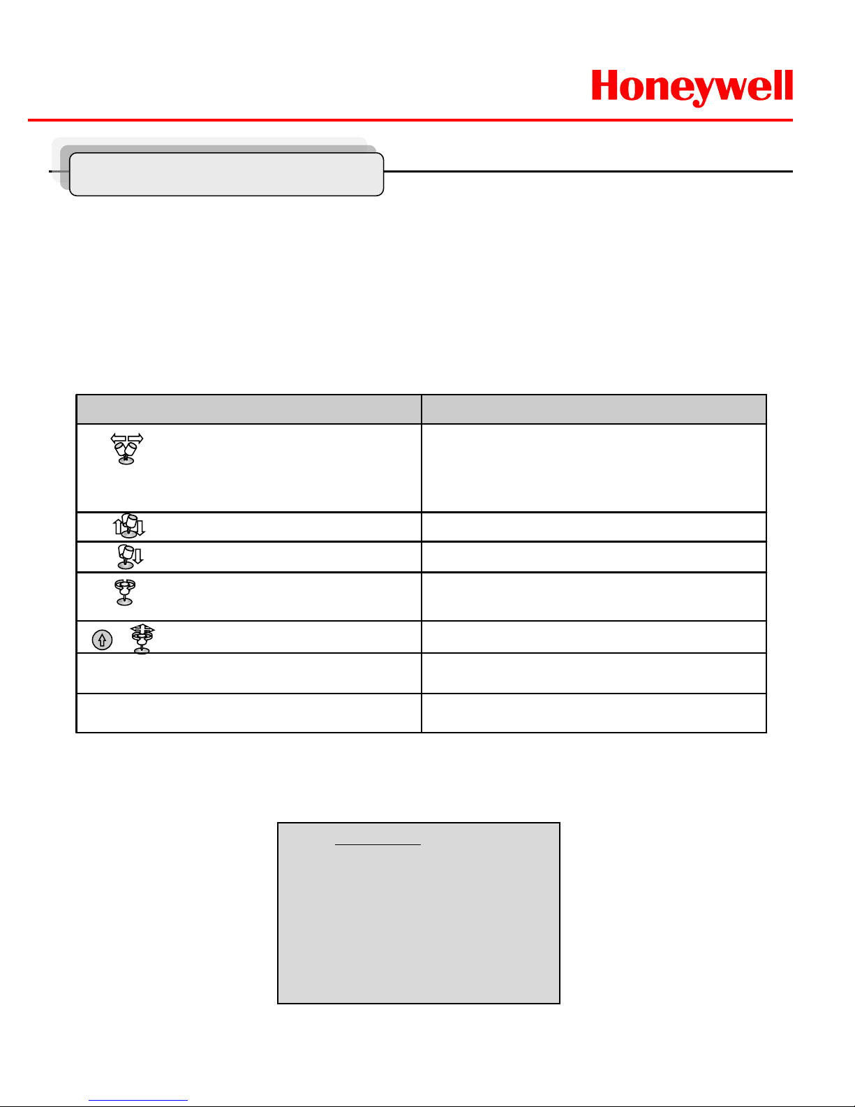
Remote Controller
1. POWER
Power on/off.
2. NUMBERS
Numeric keypads (0~9),
3. Camera Address (ID)
Change camera ID.
Number + CAM
4. WRITE PRESET(1~99)
Saves camera picture’s condition.
Number + SAVE
5. PRESET(1~99)
Recall preset.
Number + PRESET
6. HOME
Immediately calls Home function.
7. MENU
OSD menu on.
8. DOWN / UP / LEFT / RIGHT
Moves up/down in the menu.
Moves left/right in the menu.
Decreases/increases control.
9. ZOOM
Zoom in/out
10. FOCUS
Controls Focus.
11. IRIS
Controls Iris.
Page 37

HWLKS-C-M-1918
Honeywell
- 37 -
Optional Accessories
Models
1. EXPTZ-WL: Wall mount bracket designed to mount the EXPTZ Series Camera
directly to a load-bearing vertical surface.
2. EXPTZ-CN: Corner adapter B r acket for use with the EXPTZ-WL to mount the
EXPTZ Series Camera t o the cor ner of a s tr uc tur e.
3. EXPTZ-PL: Pole adapter Bracket for us e with the EXPTZ-WL to mount the
EXPTZ Series Camera to a vertical pole or itself to mount the EXPTZ
Series to a horizontal pole.
* Recommended pole diameter is 5 to 10 inches (12.7 to 25.4 cm).
General
EXPTZ-WL EXPTZ-CN EXPTZ-PL
Material SUS316 Polished SUS316 Polished SUS316 Polished
Maximum Load 50kg 50kg 50kg
Unit Weight 6.5kg 4.8kg 4.5kg
Note: These M ounti ng Accessories ar e not s uppl ied with the EXPTZ Series units.
These are purchasing par ts.
4. EXPTZ-SS: Sun Shield Bracket for blocking the direct radi ant heat so that it can
be safer against high temperature.
5. EXWJ400 : Water jet for washing and cleaning dust of front window .
Page 38

HWLKS-C-M-1918
Honeywell
- 38 -
Optional Accessories
EXPTZ-WL
EXPTZ-CN
Unit (mm)
Unit (mm)
Page 39

HWLKS-C-M-1918
Honeywell
- 39 -
Optional Accessories
EXPTZ-PL
Unit (mm)
EXPTZ-SS
Page 40

HWLKS-C-M-1918
Honeywell
- 40 -
• IECEx Grade Exd IIC T6 IP66.
• For use in variety of harsh and/or hazardous environments,
including marine env ironment.
• Specialized for High Speed EXPTZ Series.
• Easy to installation.
• Easy to clean any dried dust on the glass.
<Key Feature>
EXWJ400 _ Explosive water jet
Material SUS304
Thickness 1.2mm
Size 350(W) x 340(H) x120(D)
Weight 12kg(include Liquid)
Nozzle Ø1.0
Water Capacity 4.0L
TUBE Ø6.0 X 3m
Rated Voltage DC 12 V
Maximum Current 1.0A
Input 20W
Maximum Pressure 25 psi (1.8kgf/cm2)
Water Temperature 0℃ ~ 40℃
* The temperature can be lower until -10℃ depended on thermal
properties of liquid of insi de tank such as antifreeze.
<Specification>
<Components>
A. Water Jet package
B. Tube
C. Nozzle install bracket
Explosive proof Washer & Water pump housing system
EXWJ400
Optional Accessories
Page 41

HWLKS-C-M-1918
Honeywell
- 41 -
EXWJ400 Schematic & Operating
EXPTZ Series
EXWJ400
CAUTION
1) If EXWJ400 is applied to EXPTZ, the alarm-out can’t
be used.
2) It is recommended that the water-Jet tank should be
located on equal or lower (under 3m) level than the
nozzle location.
POWER
AC 100~240V
BNC
MAIN MONITOR
DATA1 DATA2
+ - -+ + -
J-BOX REAR
J-BOX FRONT
KEYBOARD CONTROLLER
HTX-5000
REAR
DATA 2 DATA 1
DC 12V
RS 485
1 DOME 2
IN
OUT
DVR
RS 232C
ALARM/DVR
DC 12V
SLAVE
DC 12V
+
-
RS 485
+
-
Alram out
COM
N/O
Pump
Motor
+
-
RS 485
Check Valve
Page 42

HWLKS-C-M-1918
Honeywell
- 42 -
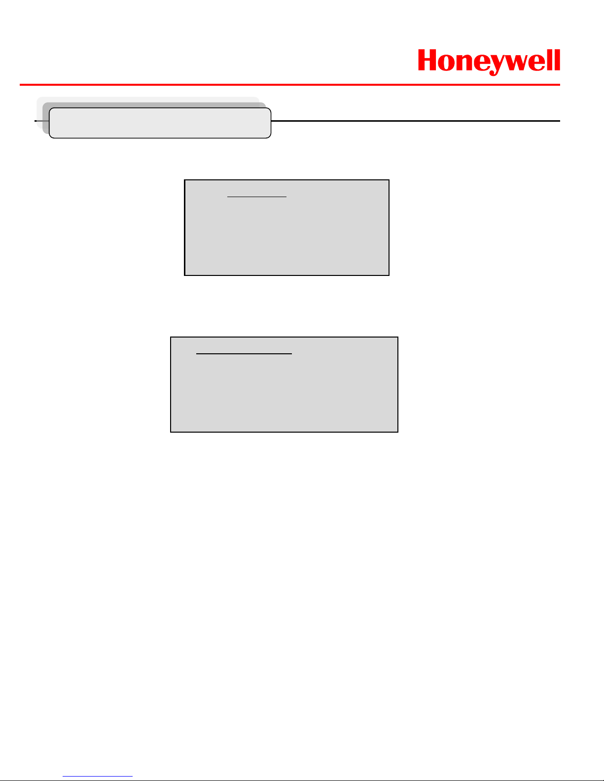
Water jet
① Set washing position
-.Move the window face to nozzle
by using pan/tile and save the
position on preset 59.
② Press and button.
(88+ Preset) at Pelco Protocol
- Set the specific position to wash
front window toward the nozzle on
preset 59.
-
Run washing and wiping.
4
Check water level in
the tank
periodically.
[ Do following step to operate water jet function ]
1. Save the location of nozzle position (washing) on Preset 59.
* First of all, The EXPTZ pan/tilt direction should be decided and saved that window glass of c amera housing toward nozzle
of water jet on preset 59.
( Refer to the “Program and Function Operating 1-2 preset” about preset method)
2. Push The [4+On] button on HTX-5000 Keyboard.
* Push the 88+preset button at Pelco protocol.
Result : 1) Pan/Tilt’s moving to nozzle position (location Preset 59 )
2) Auto-Stop after Spray water & Wiping ( 3 sec, 5 Wiping )
3) Pan/Tilt’s moving back to the previous position
EXWJ400 Schematic & Operating
Page 43

HWLKS-C-M-1918
Honeywell
- 43 -
Dimensions
EXPTZ
Page 44

HWLKS-C-M-1918
Honeywell
- 44 -
Dimensions
EXWJ400
Page 45

HWLKS-C-M-1918
Honeywell
- 45 -
Product Warranty Guide
For more information
----------------------------------------------------------------------------------------------------------------------------------------
-----------------------------------------------------------------------------------------------------------------------------------------
Warranty and Service
Subject to the terms and conditions listed on the Product Warranty Card,
during the warranty period Honeywell will repair or replace, at its sole
option, free of charge, any defective products returned prepaid.
In the event you have a problem with any Honeywell product, please call
Customer Service for assistance or to request a Return Merchandise
Authorization (RMA) number. See the back cover of this document for
contact information.
Be sure to have the model number, serial number, and the nature of the
problem outlined for the technical service representative.
Prior authorization must be obtained for all returns, exchanges, or credits.
Items shipped to Honeywell without a clearly identified Return Merchandise
Authorization (RMA) number may be refused.
Page 46

Honeywell Security Group.
Honeywell Co., Ltd.
Printed in Korea
G-113497-02
 Loading...