

Page 1

Experion PKS
Release 516
Quick Builder User's Guide
EPDOC-XX91-en-516A
August 2020
Page 2

DISCLAIMER
This document contains Honeywell proprietary information.
Information contained herein is to be used solely for the purpose
submitted, and no part of this document or its contents shall be
reproduced, published, or disclosed to a third party without the
express permission of Honeywell International Sàrl.
While this information is presented in good faith and believed to be
accurate, Honeywell disclaims the implied warranties of
merchantability and fitness for a purpose and makes no express
warranties except as may be stated in its written agreement with and
for its customer.
In no event is Honeywell liable to anyone for any direct, special, or
consequential damages. The information and specifications in this
document are subject to change without notice.
Copyright 2020 - Honeywell International Sàrl
2
Page 3

CONTENTS
Contents 3
Chapter 1 - About this guide 11
Chapter 2 - Getting started with Quick Builder 13
Starting Quick Builder 15
Layout of the main window 17
Navigation pane 18
Managing deleted items 19
List View 19
Properties pane 21
History pane 21
Contents
Library pane 22
Toolbar 23
The Jumpbar 24
Status Bar 24
Shortcut menus 24
Basic Quick Builder tasks 25
Enabling project components 26
Capturing changes to a project in the audit log 26
Comparing online and offline configurations 28
Adding items 29
Deleting and restoring deleted items 30
Modifying items 31
Filtering items 32
Searching for items 34
Selecting items 34
Renaming items 35
3
Page 4

Contents
Duplicating items 37
Copying and pasting items 37
Pasting items from a spreadsheet 39
Dragging and dropping items 40
Importing items from a definition file 40
Uploading an item's definition from the server 42
Managing and using add-ins 43
Building a system printer 45
Working with projects 46
Setting Quick Builder project options 47
Creating a new project 47
Migrating old Quick Builder projects 50
Opening an existing project 51
Exporting project data 52
About exporting results of Floating Point data to CSV files 54
Downloading a project 55
Locking a project 58
Opening files listed in the Results dialog box 59
Improving Quick Builder's performance 59
Chapter 3 - Building controllers or channels 61
Building controllers and channels 62
About generic and user scan task controllers 64
Creating a generic controller 64
Point parameter address syntax for a generic controller 65
Creating a user scan task controller 66
Point parameter address syntax for a user scan controller 66
Generic and user scan task controller and channel properties 68
Main properties for a generic channel 68
Main properties for a generic controller 70
4
Page 5

Contents
Main properties of a user scan task channel 71
Main properties for a user scan task controller 73
Modifying a controller or channel after download 75
About scanning 79
Periodic scanning 79
Exception scanning 80
Demand scanning 80
Dynamic scanning 81
About scan packets 81
Building Controller Integration Mappings 82
About Controller Integration Mappings 82
Importing Integration Mappings 85
Exporting Integration Mappings 85
Creating and Modifying Integration Mappings 86
Supported Controller Integration Mapping syntax 89
Example RTU2020 Integration Mapping 103
Chapter 4 - Building servers 106
Creating a server 107
Main properties for a server 107
Sizing limits for the server 108
Upload and download paths for a server 108
Server specific options 108
History options for a server 110
Chapter 5 - Building a Flex Station 112
About Station types 113
About security types 113
Creating a Flex Station 114
Main properties for a rotary Station 114
5
Page 6

Contents
Main properties for a static Station 115
Chapter 6 - Building and configuring points 118
Building points 121
Assigning points to an asset 121
Accumulator points 122
Main properties for an accumulator point 122
Alarm properties for an accumulator point 124
Analog points 126
Main properties for an analog point 126
Alarm properties for an analog point 128
Control properties for an analog point 131
Auxiliary properties for an analog point 133
About drift deadbands 134
Container points 135
Defining the structure of a container point 135
Creating container points 136
Main properties for a container point 137
Using an existing point detail display as the associated display 138
Creating a point detail display for a container point 138
OPC advanced points 140
Main properties for an OPC advanced point 140
Importing OPC advanced point definitions from a spreadsheet 141
OPC parameters for an OPC advanced point 145
Status points 145
Main properties for a status point 146
Alarm properties for a status point 148
Control properties for a status point 150
Configuring the Raise and Lower buttons for OP control 154
Configuring algorithm parameters 155
6
Page 7

Contents
Display-related properties 155
History collection properties 156
Subscribing to non-scanned parameters 159
Creating or editing scripts 161
Creating scripts 161
Electronic signature related properties 161
Configuring points for electronic signatures 162
Configuring user-defined parameters 163
Adding a variable user-defined parameter 164
Adding a constant user-defined parameter 165
Adding a database reference user-defined parameter 165
Adding a parameter reference user-defined parameter 166
About user-defined scanned parameters 166
Adding a scanned analog user-defined parameter 169
Adding a scanned status user-defined parameter 170
Adding a scanned string user-defined parameter 172
Adding a custom user-defined parameter 172
Adding multiple user-defined scanned parameters 173
Modifying multiple user-defined scanned parameters 181
Importing/uploading specialized point configurations 181
Specifying point parameter addresses 182
Using Address Builder 183
Using Address Builder with an Integrated Controller connected 185
Automated Point Generation for an Integrated Controller 186
Chapter 7 - Building Equipment Templates 192
About building equipment templates 193
Creating equipment templates 194
Exporting templates from the Template Library 196
7
Page 8

Contents
Updating equipment by modifying its equipment template 197
Deleting an equipment template 198
Configuring equipment templates 199
Configuring the Template properties 200
Creating a Related Equipment table 202
Configuring Point and Equipment properties 203
Editing properties in Microsoft Excel 209
Creating a tabular view 209
Creating a trend view 210
Configuring the Summary view 211
Template properties 214
Configuring the Tabular view 217
Summary view properties 220
Point properties 222
Equipment properties 224
Shape properties 227
Chapter 8 - Building and configuring Equipment 232
Building equipment 233
Importing equipment templates to the Template Library 234
Modifying equipment properties 235
Details for an Equipment item 236
Point references for an Equipment item 236
Associated items for an Equipment item 237
Relationships for an Equipment item 237
Configuring equipment relationships 239
Assigning equipment to a different asset 240
Deleting equipment 240
Chapter 9 - Building Electronic Flow Measurement (EFM) 242
8
Page 9

Contents
Building EFM meters 243
Main properties for an EFM meter 244
Collection and export properties for an EFM meter 245
Managing EFM meter templates 247
Main properties for an EFM meter template 250
Configuration Log properties for an EFM meter template 254
Interval Log properties for an EFM meter template 257
Daily Log properties for an EFM meter template 260
Alarm and Event properties for an EFM meter template 264
Configuration Record Log properties for an EFM meter template 268
Ultrasonic Log properties for an EFM meter template 272
Composition Log properties for an EFM meter template 275
Gas Quality Log properties for an EFM meter template 278
Liquid Batch Log properties for an EFM meter template 281
Data Export properties for an EFM meter template 284
Defining enumeration mappings for CFX 286
CFX enumeration mappings 288
Configuring CALC data types 297
Defining EFM CSV data export formats 298
Defining the monthly export format 301
Managing EFM schedules 302
Managing meters and meter templates 304
Uploading EFM configurations from the server 305
Exporting and importing EFM configurations 306
Collecting and exporting EFM data 306
About tamper detection of EFM data 309
Chapter 10 - Algorithms 312
Configuring PV algorithms in Quick Builder 313
9
Page 10

Contents
PV Algo 4: General Arithmetic 313
PV Algo 5: Production 314
PV Algo 7: Run Hours 315
PV Algo 10: General Logic 316
PV Algo 12: Composite Alarm Processing 317
PV Algo 15: Integration 319
PV Algo 16: Cyclic Task Request 320
PV Algo 20: Advanced Arithmetic 321
PV Algo 21: Advanced Logic 322
PV Algo 22: Piecewise Linearization 323
PV Algo 64: Maximum/Minimum 324
PV Algo 68: Value Transportation 325
Configuring action algorithms in Quick Builder 326
Action Algo 11: Composite Alarm 326
Action Algo 68: Value Transportation 327
Action Algo 69: Status Change Task Request 328
Action Algo 70: Status Change Report Request 329
Action Algo 71: Queued Task Request 329
Action Algo 72: Status Value Transportation with Mapping 329
Action Algo 74: Status Change USKB LED Request 331
Action Algo 75: Status Point Notification 332
Action Algo 76: Analog Point Notification 332
Action Algo 77: Status Change Display Request 333
Action Algo 78: Group Control of Points 334
Action Algo 79: Status Change Alarm Group Inhibit 335
Action Algo 80: Status Change Alarm Area Inhibit 336
10
Action Algo 92: Queued Task Request 336
Creating a composite alarm hierarchy 337
Notices 339
Page 11

CHAPTER
ABOUT THIS GUIDE
1
This guide describes how to use Quick Builder to configure system
items, such as controllers (other than Process Controllers), points,
Flex Stations, and printers.
Revision history
Revision Date Description
A August 2020 Initial release of document.
11
Page 12

Chapter 1 - About this guide
12
Page 13

CHAPTER
2
GETTING STARTED WITH QUICK BUILDER
In Configuration Studio, you use Quick Builder to create and maintain
a configuration database that defines system items such as
controllers, points and Flex Stations. (For details about configuring
Console Stations, see the Server and Client Configuration Guide.)
When you are satisfied with your configuration, you download it, or
selected parts of it, to the Quick Builder (online) database on the
Experion server.
To modify any part of your configuration, you need to upload (or
backbuild) items from the server (online) database into Quick Builder,
make the required changes, and then download the changes to your
server database.
You can also create an offline Quick Builder database (a database
connected to an SQL server rather than an Experion server) to
configure your entire system and then download that configuration to
the Quick Builder database on the Experion server at a later time. This
offline database is also referred to as a Quick Builder project.
TIP: Offline databases are vulnerable from a security
perspective. Ensure that you save any offline databases in a
secured path.
Quick Builder support for multiple users
Multiple users can open a Quick Builder project in different nodes
simultaneously and perform configuration activities.
Rules have been established within Quick Builder to handle conflicts
between user actions, which means that occasionally you could be
stopped from completing an update to the database if another user is
performing a similar action, or if the item has been modified in some
way since you started your update.
For example, if you modify, add, or delete an item and then try to
download those changes to the Experion server while another user is
also attempting a download, an error message is displayed and you
will need to wait to download your changes until the other user’s
download is complete.
13
Page 14

Chapter 2 - Getting started with Quick Builder
In this section:
Starting Quick Builder 15
Layout of the main window 17
Basic Quick Builder tasks 25
Working with projects 46
14
Page 15
Starting Quick Builder
When starting Quick Builder, you can connect to either an online
Quick Builder database on an Experion Server, or to an offline
database on an SQL (non-Experion) server. When working offline, you
can create Quick Builder projects, that can later be downloaded to the
Quick Builder database on an Experion server.
Prerequisites
To create a Quick Builder project you must have a minimum of SQL
Server Express installed.
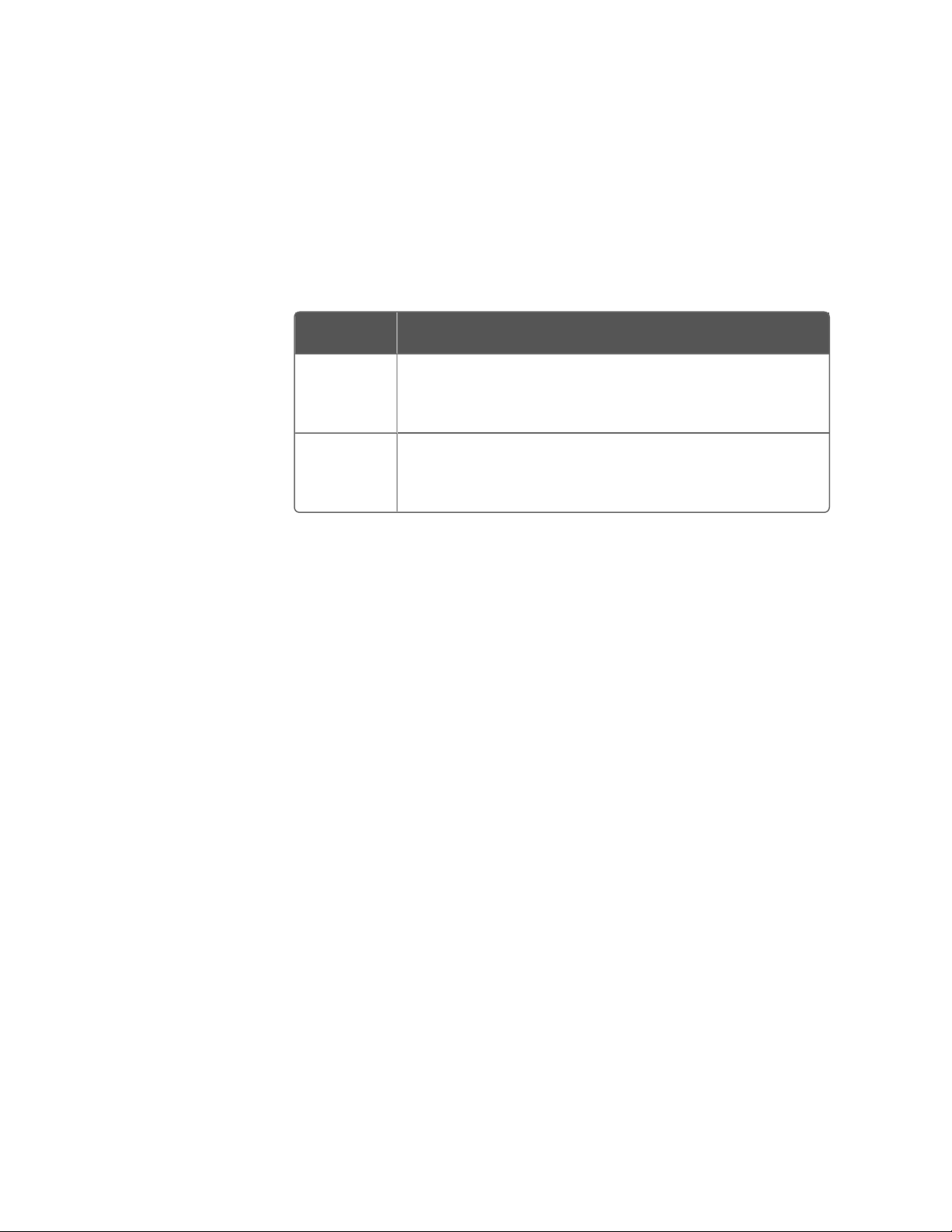
To start Quick Builder
1. Start Configuration Studio.
The Connect dialog box appears.
Chapter 2 - Getting started with Quick Builder
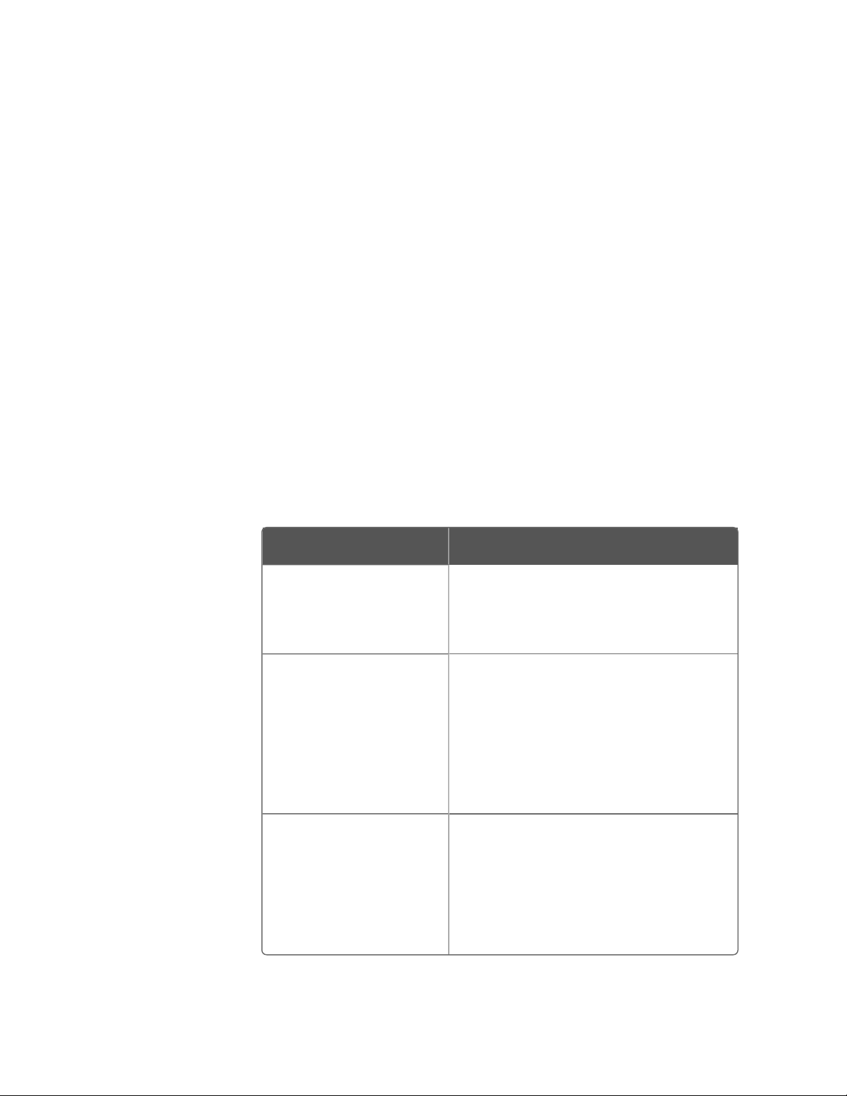
2. Depending on the environment you want to work in, use one of the
following connection options:
Option Description
To work in the Quick
Builder database on
your local Experion
Server.
To work in the Quick
Builder database on a
remote Experion
Server.
To work in an offline
Quick Builder database
on an SQL Server.
On the Local Targets tab, select the
system or server you would like to
connect to.
1. On the Other Targets tab, select
either Experion PKS System or
Experion PKS Server from the
Target type list.
2. Select the system or server you
would like to connect to from
the Target name list.
1. On the Other Targets tab, select
Quick Builder Database from the
Target type list.
2. Select the SQL server you would
like to connect to from the
Target name list.
15
Page 16
Chapter 2 - Getting started with Quick Builder
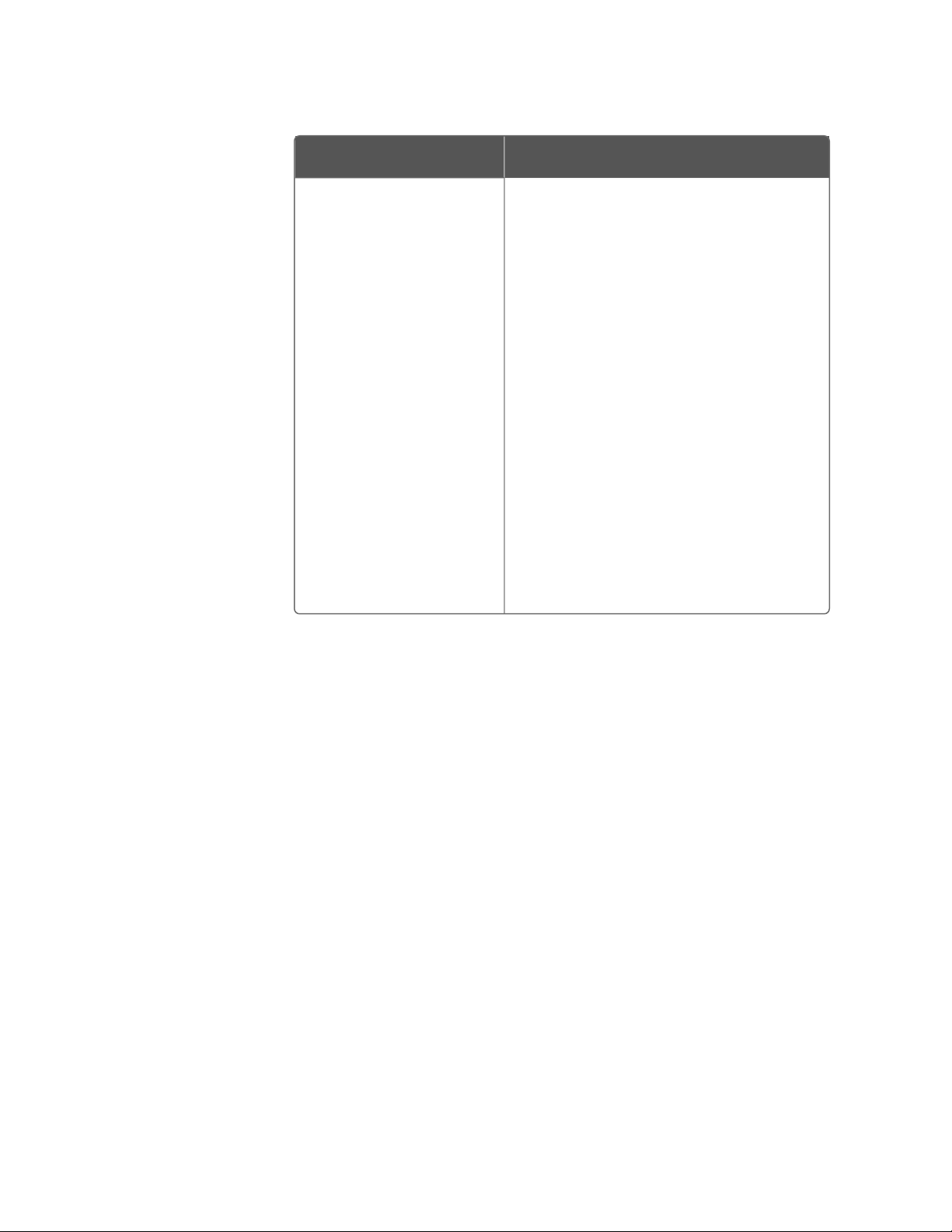
Option Description
3. To open an existing project:
a. Select the Open Existing
Project option
b. Click Search Location to list
the databases existing on that
server.
c. Select the database you
would like to connect to from
the list provided.
4. To create a new project:
a. Select the Create Project
option
b. Type a name for the new
project in the Project Name
field.
3. Click Connect.
If you chose to connect to a Quick Builder database on an
Experion server, the Login to Server dialog box appears. Enter your
credentials and click OK, then skip to step 6.
If you chose to connect to, or create, a Quick Builder project on an
SQL server, the Enable Components dialog box appears.
4. In the Enable Components tab, the check boxes indicate the
components that are enabled by default for your system licence,
and the number of each item that has been created for each
component. Use the check boxes to enable and disable
components as required, then click OK.
5. In the SCADA Control list, click any of the available options, such as
Build Channels.
Quick Builder appears. Your Quick Builder access privileges are
the same as for Configuration Studio.
16
Page 17
Chapter 2 - Getting started with Quick Builder
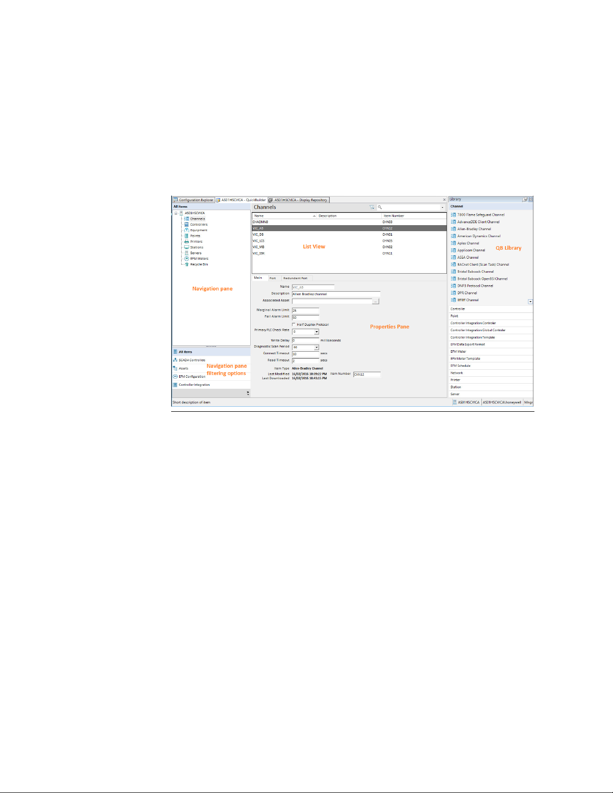
Layout of the main window
The following figure shows the layout of the Quick Builder window,
regardless of whether you are working in an online or an offline
database.
Figure 2-1: Quick Builder window layout
In this section:
17
Page 18
Chapter 2 - Getting started with Quick Builder
Navigation pane
A navigation pane on the left-hand side of the Quick Builder window
contains items that can be created and configured in Quick Builder.
The following table lists the views that you can choose in the
navigation pane, and the contents of those views.
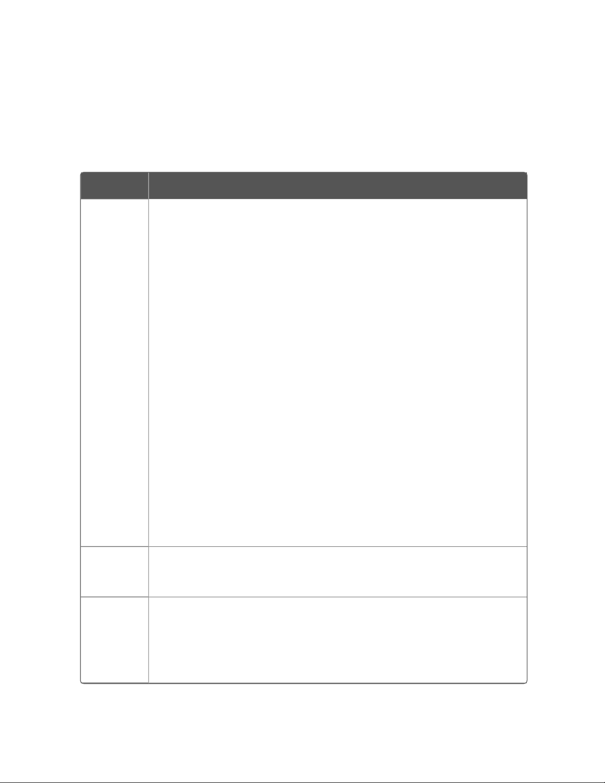
Category Items and descriptions
All items Displays a tree containing all item types supported by Quick Builder:
l Channels (interfaces that enable servers to communicate with
controllers)
l Controllers (field devices such as PLCs, loop controllers, and so
on)
l Points
l Stations (the Operator interfaces)
Quick Builder configures only Flex Stations, the standard type of
Station. (For details about configuring Console Stations, see the
topic titled "Configuring a Console Station" in the Server and Client
Configuration Guide.)
l Printers
l Meters
l Servers
l Equipment
l Recycle bin, which is a holding area for items that have been
deleted from their parent category but have not yet been
permanently deleted and therefore can be recovered if needed.
l Unassigned items
SCADA
Controllers
Lists channels and controllers defined for this server. Selecting a
controller displays a list of the points assigned to that controller in the
List view.
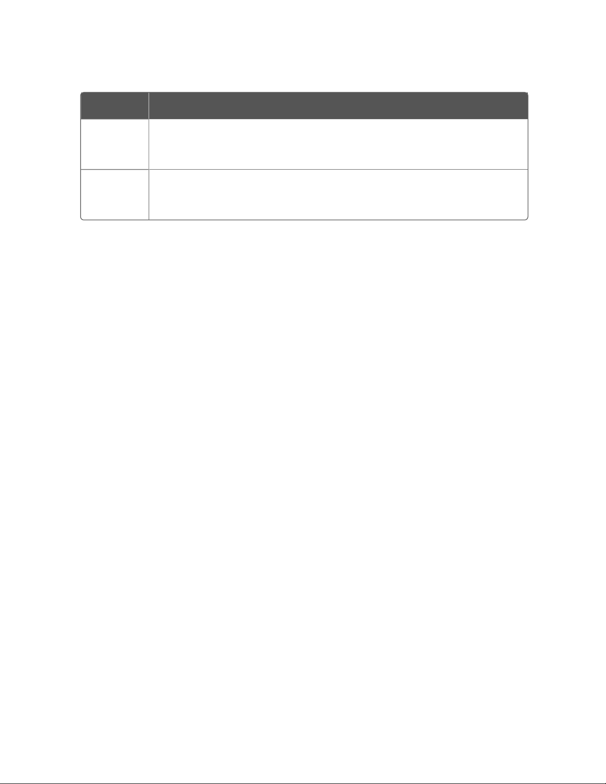
Assets Lists assets that have been downloaded from the server. Selecting an
asset displays a list of the items associated with that asset in the List
view.
18
Adding, editing, duplicating, and renaming operations are not permitted
in the Asset view.
Page 19
Category Items and descriptions
Chapter 2 - Getting started with Quick Builder
Electronic
Flow
Meters
Controller
Integration
Lists Electronic Flow Meters that have been defined for this server.
Selecting a meter displays a list of the items associated with that meter
in the List view.
Launches the configuration forms through which points can be
generated for those controllers where the Integration check box has
been enabled.
Managing deleted items
The Recycle Bin is a holding area within the Navigation pane, where
items you have deleted from other groups are 'marked for deletion',
rather than being actually deleted.
To undelete an item and return it to its original group, right-click the
item and choose Undelete from the shortcut menu.
Note the following points:
n Deleted items will be permanently deleted if you select the
Automatically Download Deletions option when you download a
project (and the download is successful).
n You should not permanently delete items that you have previously
downloaded to the server—if you attempt to do this a warning
message appears. (If you choose to delete items that have been
downloaded, the project and the server database will lose
synchronization—although the item will no longer exist in the
project, it will still be defined in the server database.)
n Quick Builder allocates an item number to each item. Items in the
Recycle Bin retain their numbers until you permanently delete
them. This has no significance unless you reach an item number
limit for your license. For example, if your license allows 40
Stations, and you have already created 40 Stations (including
deleted ones), you cannot add any more until you
delete/download those that have been deleted and are still being
held in the Recycle Bin.
List View
When you select a group of items in the Navigation pane, such as
Printers, Stations, or Points, a list of the items that have been created
within that group is displayed in List View. If no items appear in the
List View, it means that none have yet been created.
19
Page 20
Chapter 2 - Getting started with Quick Builder
You can use List View to edit, delete, and sort items.
TIP: As Quick Builder projects can be modified by more than
one user at a time, you may find that changes made by other
users sometimes appear in the List View when you move from
one item to the next, or when you change focus in the
Navigation pane. Refreshing the view will also display changes
made by other users.
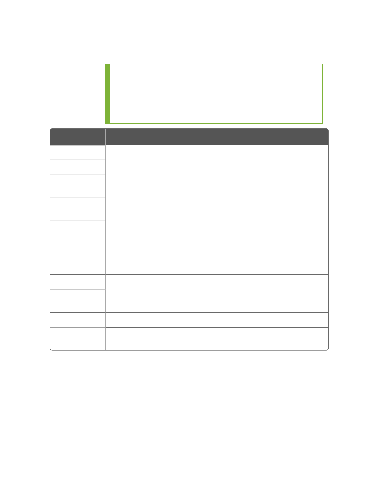
Item type Description
Points Standard points.
Servers Servers, which use the databases created by Quick Builder.
Controllers Controllers, the field devices such as PLCs, loop controllers, and so
on.
Channels Channels, the interfaces that enable servers to communicate with
controllers.
Stations Stations, the operator interfaces
Quick Builder configures only Flex Stations, the standard type of
Station. (For details about configuring Console Stations, see the
topic titled "Configuring a Console Station" in the Server and Client
Configuration Guide.)
Printers Printers.
RecycleBin A holding area for deleted items, which works in the same manner
as the Windows' Recycle Bin.
Trends/Groups Station displays to which you can add points.
Networks The interface that enables servers and point servers to
communicate with channels and controllers.
Customizing the List View
By default, the List View contains columns displaying an item’s major
properties, such as its name and description. You can, however,
customize the List View to show other properties by adding, removing ,
or reordering columns. You can also sort columns to be either
ascending or descending, and the view will reorder accordingly.
20
Page 21

Chapter 2 - Getting started with Quick Builder
To customize the List View
1. Choose ViewColumns.
The Columns dialog box appears.
2. Select the names of the columns you wish to display from the
Details list.
You can use the options in the Select fields from list to filter the
columns shown in the list.
3. Use the Move Up and Move Down buttons to change the order of
how the columns will appear.
4. Click OK to close the dialog and refresh the List View.
Properties pane
You use the Property Pane to view and edit the properties of the item(s)
selected in the List View.
Because an item has so many properties, they are grouped by tab. For
example, if you wanted to see the display-related properties of a
selected point, you would click the Display tab.
The Property Pane is modeless, which means that the selected item(s)
change as soon as you select another item, or perform an action such
as downloading.
The Property Pane also changes as follows when you select several
items:
n Any property whose value is not identical for all selected items is
grayed out. For example, if you select two status points, Point ID
will be grayed out because every point has a unique ID.
n If the items are of different types, such accumulator and status
points, the Property Pane only displays tabs and properties that are
shared by all selected items.
If you edit a property when several items are selected, you make that
same change to every selected item. For example, if you select a
number of accumulator and status points, you can change the PV
Source Address or the PV Scan Period because both properties are
common to both point types.
History pane
Every time a display is modified, those versions are saved and can be
viewed in the History Pane at the bottom of the Display Repository.
21
Page 22
Chapter 2 - Getting started with Quick Builder
From the History Pane you can perform several actions on a display
version. You can:
n Approve or Reject a version read for publication to the Experion
server
n Publish a display version to the Experion server
n Update a version of a display in your working folder to match the
latest version on the Experion server
The display versions are listed in a table, containing the following
information:
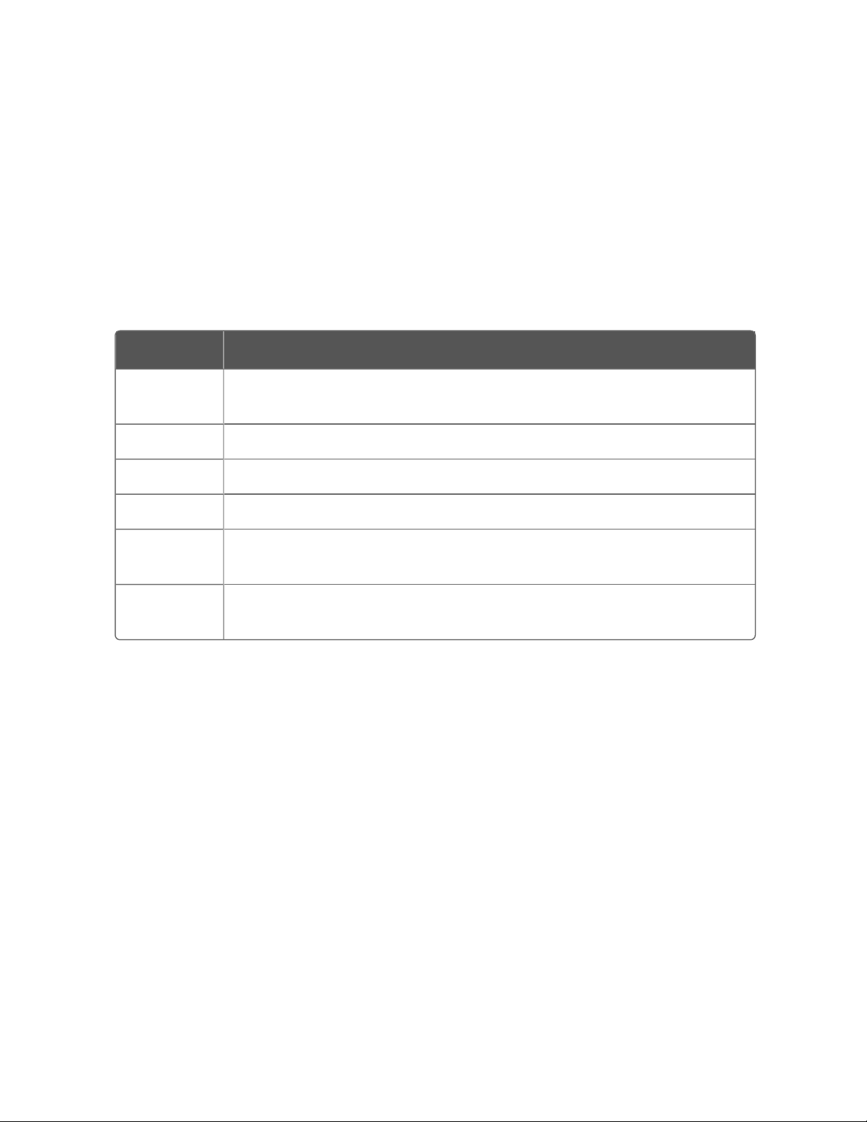
Item Description
User The ID of the user who saved that version of the display in this
database.
Date The date that the version was saved.
Version The version number of the display.
Action The system action that was performed to that version of the display.
Comment Comments added by the user when they saved that version of the
display.
Ready to
Validate
The display is ready for testing and validation prior to being published
to the Experion server.
Library pane
The Library pane on the right hand side of the Quick Builder window
contains templates that can be used to create instances of items in
Quick Builder. The templates are organized into categories to identify
their types:
n Channels
n Controllers
n Points
n Servers
22
n Printers
n Stations
n and so on
Page 23
When creating and importing templates, you can create custom
categories that will then appear in the Library pane. These might
include industry areas, such as Oil and Gas, or Coal Seam Gas.
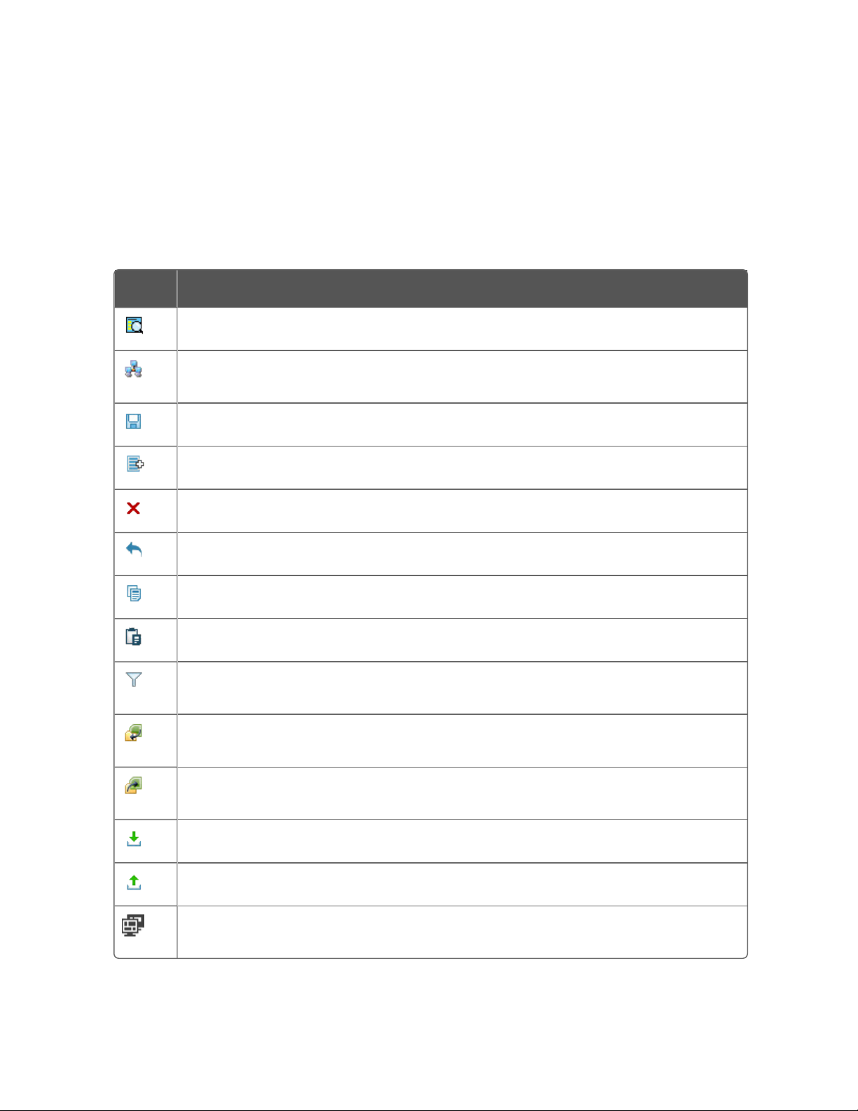
Toolbar
The toolbar provides speedy access to commonly used commands.
Button Description
Search. Searches the Quick Builder database for items such as points.
Change configuration target. Allows you to change to another server, system,
or Quick Builder database.
Save. Saves the project.
Add. Adds one or more items to the project.
Chapter 2 - Getting started with Quick Builder
Delete. Moves the selected items to the Recycle Bin.
Undo. Undoes the previous action.
Copy. Copies the selected items to the clipboard.
Paste. Pastes the clipboard's contents into the display.
Custom Filter. Opens the Custom Filter dialog box, which you use to filter out
(hide) items that are of no immediate interest.
Import. Opens the Select file to Import... dialog box, which you use to locate
and select the file you want to import.
Export. Opens the Export dialog box, which you use to export files from the
current Quick Builder database.
Download. Downloads all or some of the project to the server database.
Upload. Uploads configuration data from the server into a project.
Compare. Compare items in the current project to those in the Quick Builder
database on the server.
23
Page 24

Chapter 2 - Getting started with Quick Builder
The Jumpbar
You use the Jumpbar to quickly select an item in the List View. (Note
that you will not be able to locate and select an item if it has been
filtered out.)
To find items:
1. Click anywhere in the Jumpbar.
2. Type the name of the item you are searching for and press Enter.
Quick Builder finds the first matching item.
You can use one or more wildcards (*) to find items whose full
names you do not know, for example *ana*, which will return items
containing the text ana in its name.
To select an item:
1. Click the Jumpbar.
2. Type the item's name and press Enter.
To move between items, select the item from the Jumpbar list and
press Enter. The Jumpbar remembers the last 20 items you specified.
Status Bar
The Status Bar displays a short description of the selected property (or
its valid values if the current value is incorrect). The right hand side of
the Status bar also displays the name of the connected server, the
name of the current user, and the current security level.
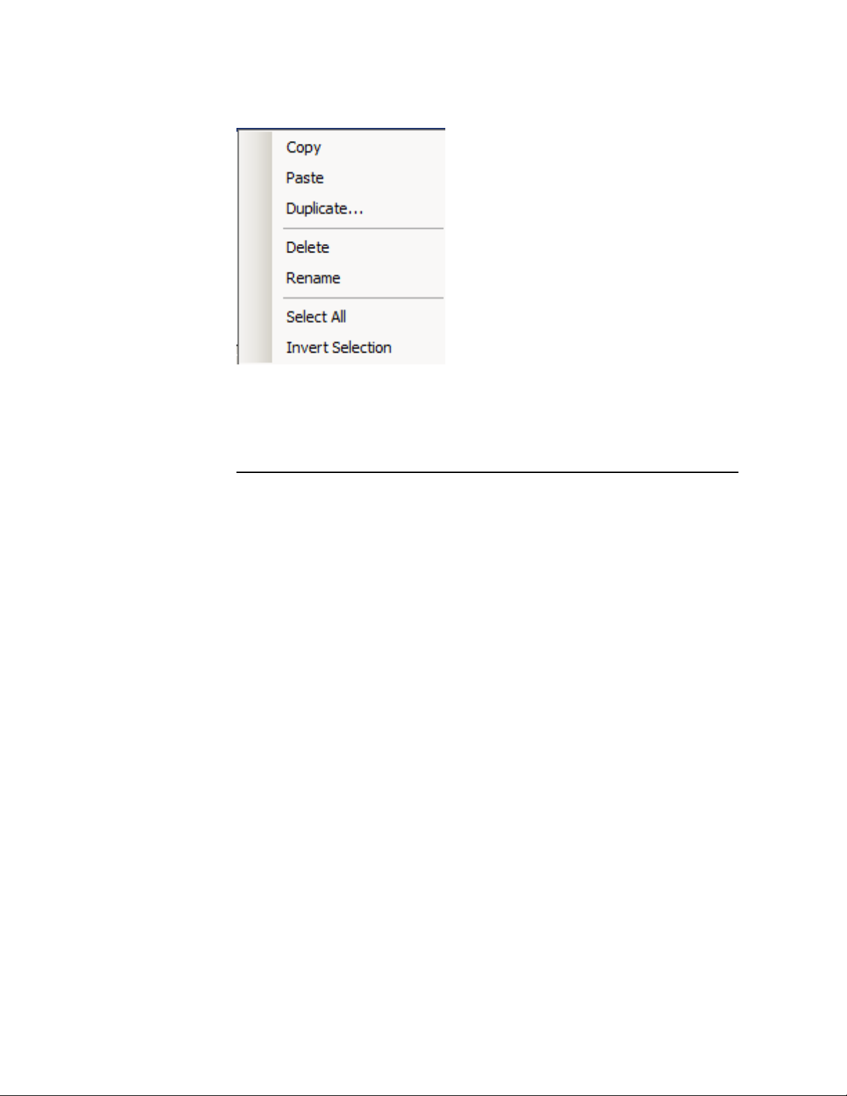
Shortcut menus
If you right-click an item type icon (in List View), a shortcut menu
appears that provides speedy access to commonly used commands.
In the List View, you can highlight multiple items before opening the
shortcut menu.
Figure 2-2: List View Shortcut menu
24
Page 25
Basic Quick Builder tasks
This section outlines the basic tasks you can perform with Quick
Builder.
Chapter 2 - Getting started with Quick Builder
In this section:
25
Page 26

Chapter 2 - Getting started with Quick Builder
Enabling project components
When you first start a new Quick Builder project, or when you add new
component types (such as devices, points, and servers) to a project,
you first need to specify them in the component manager so that you
can configure them.
TIP: When working on the Project Component Manager to
enable or disable components for a project, any other users of
the project will be asked to log off and they will not be able to
log back into the project until you have finished. For this
reason, it is recommended that you perform this action when
there is minimal user activity in the project.
To specify the components to configure
1. From the Quick Builder menu, choose Tools > Project Component
Manager.
The Project Component Manager dialog appears.
The dialog contains a list of components, such as devices, points,
and servers. It also contains a list of non-Experion components.
2. Scroll through list of components and select the check box next to
the items in your project you want to enable or disable.
3. Click OK.
A summary appears of the components being added (or removed).
4. Click OK.
Quick Builder adds the components to the project.
Capturing changes to a project in the audit log
You can capture all changes made to a Quick Builder project,
including details of the user who made the changes, in an audit log.
Audit logs are, by default, stored on the server on which they have
been enabled. You can use a combination of Robocopy scripts and
Windows Task Scheduler to automatically copy audit logs to a
network share regularly.
26
Page 27

Chapter 2 - Getting started with Quick Builder
To enable the audit log for capturing changes to a
project
1. Start Quick Builder.
For more information, see "Starting Quick Builder" on page15.
2. From the Quick Builder menu, select Servers and click the All items
tab.
A list of the servers for this project appears.
3. Select the server on which you want to capture changes, then click
the Server Specific Options tab.
4. Select the Enable audit log checkbox
All Quick Builder changes made to the project and to items on that
server will be recorded in the audit log.
Server Logger is used to store the log files, and Honeywell Log
Viewer (HLV) can be used to view the log files. You can access the
log files through a shortcut in the Start menu on the Experion
Server.
Note the following rules for the audit log:
l The maximum size for a single log file is 8MB
l The maximum number of log files is 100
l After the maximum storage is reached (800MB), the log files
will be overwritten
l It is recommended that audit log files are stored in a secure
location, and backed up periodically.
To copy an audit log and schedule regular saves to a
network share
1. From a Windows Command Prompt on the server, type robocopy
<source> <destination> [<File>[...] [<options>], where:
a. source is the path to the source directory
b. destination is the path for the destination directory
c. file is the audit log file or files to be copied
d. options is a list of the options to be included in the command.
For more information about Robocopy command options, see
https://technet.microsoft.com/en-us/library/cc733145.aspx.
27
Page 28

Chapter 2 - Getting started with Quick Builder
2. Press Enter.
The files are copied to the specified location
3. Copy your Robocopy command syntax to a Notepad file, and save
as a .BAT file so it can be re-run.
4. From the Windows Control Panel, click System and Security, and
then Administrative Tools.
5. Right-click on Task Scheduler and choose Run as Administrator.
6. Choose Action, and then Create Basic Task....
7. Enter a name for the task and a short description, then click Next.
8. Select the option that best meets your scheduling requirements,
then click Next and enter any additional scheduling information as
required.
9. Select Start a program, then click Next.
10. Navigate to and select your Robocopy script, then click Next.
11. Review the summary details, and click Finish.
Comparing online and offline configurations
You can compare items in a standalone (offline) project with those in
an online Quick Builder database either while you are configuring the
items, or before you download a project containing those items to the
database on an Experion server.
Depending on the number of items being compared, one of the
following actions will occur:
n For up to 5000 items, the comparison will occur within the Quick
Builder Compare Report, as documented below.
n For between 5000 and 100,000 items, the comparison data is
exported to a .TSV file, which can be viewed in Microsoft Excel,
Honeywell Log Viewer, or Notepad.
n For more than 100,000 items, a message is displayed stating that
the comparison could take in excess of 4 hours to complete.
A comparison report highlights any item that has changed or been
added since the most recent download of this project.
After adding and configuring items, you download all or part of your
project to the server database. Before committing to the download of
any items, you can compare them with what already exists on the
Experion server.
28
Page 29

Chapter 2 - Getting started with Quick Builder
Comparing items while configuring a project
1.
At any time while working on a Quick Builder item, click in the
tool bar.
The Compare Report appears, highlighting any difference that exists
between the item in your project and on the Experion server.
2. Click Close icon to return to Quick Builder.
Comparing items before downloading a project to the
server
1. As for any download, choose the Scope of the download and
check that the Summary contains the list of items you want to
download to the server.
2. Click Compare.
The Compare Report appears, highlighting any new or changed
items. You can use the tool bar icons to perform actions such as
l Jumping backwards and forwards between changed items in
your project or on the server
l Show all items, or only the ones that are different between your
project and the server
Click the close icon to close the compare report.
3. After reviewing the Compare Report, you can choose to either
Download the items to the Experion server, accepting the changes
as they have been highlighted in the report, or Cancel the
download to return to Quick Builder.
Adding items
To create new items
1. Use one of the following options to create a new item:
l
Click .
l From the menu bar, click Edit > Add item.
l Right-click on an item in the All items view and click Add item.
29
Page 30

Chapter 2 - Getting started with Quick Builder
l From the relevant section within the Library, drag and drop the
template for the required item into the List View.
The Add Items dialog box appears.
2. Type the number if items you want to create in the Number of items
field. If you choose to create more than one item, extra fields
appear where you can define the suffix applied to each item name.
The variable used can be numbers of letters.
3. From the Item Family list, select the applicable family. If you used a
template or a right-click menu option to invoke this dialog, this
field will default to the template type or the item you had selected
at the time.
4. From the Item Type list, select the item type.
5. In the Name text box, type in the name for this item, or you can
accept the default provided. A summary of the details you have
provided is displayed.
6. Click OK to add the item(s) to the list.
The new items appear in the List View.
As more than one user can work in a Quick Builder project at the
same time, you may notice changes occurring in the List view
other than those that you have made. These changes appear
whenever you refresh the List view.
If an item you are adding has the same name as an item added by
another user, an error message appears. If you are adding multiple
items, those that do not have conflicting names will be added
successfully, but you will need to add any conflicting items again
using a different item name.
30
7. Use the properties tabs to configure the item.
Deleting and restoring deleted items
Deleting an item moves it to the Recycle Bin, which means that you can
restore it, or undelete it, if needed.
To delete one or more items
1. Select the item(s) you want to delete in either the Navigation pane
or the List view.
2.
Click (or press Delete).
You can also delete items by:
Page 31

Chapter 2 - Getting started with Quick Builder
l Clicking FileDelete on the menu bar
l Right-clicking on an item and then clicking Delete.
The deleted items are moved to the Recycle Bin.
If you attempt to delete an item at the same time as it is being
modified by another user, a message is displayed and the item is
not deleted. If you attempt to delete multiple items, any items
being modified will be specified in the message and not deleted,
while any items not currently being modified are deleted
successfully.
3. To permanently delete items from the system, select the item in
the Recycle Bin and repeat any of the previously listed delete
options.
To restore one or more items
1. From the Recycle Bin, select the item(s) you want to restore.
2. Click FileRestore from the menu bar, or right-click on an item and
then click Restore
The restored items return to their original locations.
If you attempt to restore an item at the same time as it is being
permanently deleted by another user, a message is displayed and
the item is not restored. If you attempt to restore multiple items,
any items being permanently deleted will be specified in the
message and not restored, while any items not currently being
permanently deleted are restored successfully.
Modifying items
There are two ways to modify items in Quick Builder:
n Modify one or more properties of one item
n Modify common properties of multiple items
TIP: If you attempt to download a modified item (or items) to
the Experion server at the same time as another user is
modifying this item or the Quick Builder project, a message is
displayed and you will need to attempt the download again
later.
31
Page 32

Chapter 2 - Getting started with Quick Builder
To modify properties of one item
1. From the Navigation Pane or the List View, select the item you
would like to modify.
The properties pages for the selected item are displayed.
2. Modify the properties as required.
3. Download the modified item to the server.
To modify common properties of multiple items
1. From the List View, select the items you want to modify.
To select multiple items, hold down the Shift key and click the
mouse button to select sequential items, or the Control key and
the mouse button to select non-sequential items.
The Properties pages are selected for the selected items. The
common properties, that can be changed for all items, are shown
with editable fields. Non-common properties are not editable.
2. Modify the properties as required.
3. Download the modified items to the server.
Filtering items
It is often easier to manage items if you filter the List View to contain
only the items you want to work with.
You can filter items according to item sub-type, such as analog
points, or rotary Stations. For example, if the List View shows all points
but you only want to see analog points, select Analog Point from the
Filter Selector.
Figure 2-3: Filter Selector
32
Page 33

Chapter 2 - Getting started with Quick Builder
To filter items in the List View
1. From the Navigation Pane, select an item, such as an asset, an
equipment, or a channel, for which you would like to view items.
2. Click the Filter button to display the filter options. Options are:
l All Items
l Custom filter – opens the Custom Filter dialog where you can
build custom filters based on a combination of conditions
including property names, conditions, and values.
l A list of options relevant to the item you have selected in the
Navigation Pane. For example, if you selected Points, the
configured point types would be listed (Analog Point,
Accumulator Point, Container Point, and so on).
3. Select the filter you want to use.
The text in the List View header changes to show the filter that has
been applied, for example, Points (Status), and the List View
contents update to show only items that match the filter criteria.
To create a custom filter
1. From the Navigation Pane, select an item, such as an asset, an
equipment, or a channel, for which you would like to view items.
2. Click the Filter button and click Custom Filter.
The Custom Filter dialog appears.
3. Select the item types that should be part of this filter.
4. Use the controls provided to build your filter conditions. The
available variables are:
l Property name, for example, Scripts, Item Name, Tag.
l Condition, for example, Begins with, Contains, Equals
l Value
The list to the left of each condition statement enables you to
specify AND or OR when creating multiple conditions.
Click Save Filter to save a custom filter for future use, or click Load
Filter to load a previously saved custom filter.
5. Click OK to run the filter.
33
Page 34

Chapter 2 - Getting started with Quick Builder
The text in the List View header changes to show the filter that has
been applied, for example, Points (Status), and the List View
contents update to show only items that match the filter criteria.
Searching for items
You can use the Search function to search for a keyword included in
the name of those items in the List view.
To search for an item using the keyword search
1. In Quick Builder type a keyword, or some characters, you would
like to search for within the items listed in the List View.
The Search function also supports wild card searching, such as ?
and *. For example, a search string of SVR?CH01 will return items
with the fourth character in the item’s name being any
alphanumeric, while a search string of SVR2CH* will return all
items with names starting with SVR2CH.
Selecting items
You have the option of selecting items in List View to edit or delete
properties. Selected items are shown in reverse color.
ATTENTION: If you select more than one item, the Property
Pane only displays tabs and properties that are shared by every
selected item. If the selected items have different values for a
particular property, that property is grayed-out without any
value. If you edit a shared property, you make that change to all
selected items.
To select Do this
One item Click it (or the selection box to its left).
All items of a particular
type (points, controllers
and so on)
A contiguous group of
items
1. Select one item of the required type.
2. Choose EditSelect All.
1. Click the first item you want to select.
2. Press and hold down the SHIFT key, and then click
the last item you want to select.
34
Alternatively, you can drag across the items to select
Page 35

To select Do this
them. (You need to start dragging to the right of the
Source Address column.)
If you want to clear one or more selected items, press
and hold down the CTRL key and then click each item
you want to clear.
Chapter 2 - Getting started with Quick Builder
Several non-contiguous
1. Click the first item that you want to select.
items
2. Press and hold down the CTRL key, and then click
each remaining item you want to select.
If you want to clear one or more selected items, press
and hold down the CTRL key and then click each item
you want to clear.
An item by name Use the Jumpbar.
Renaming items
You can change an item's name—point ID in the case of a point—
provided you have not downloaded it to the server.
Note the following considerations:
n The item name of an entity is automatically generated based on
the renamed point ID (tag name).
n An item has been downloaded if there is a date in the Last
Downloaded property on the Main tab.
n If you need to rename items that have been downloaded, see the
procedure below titled "To rename downloaded item(s)." The
procedure involves deleting the items from both the project and
server database, and then recreating them with their new names.
TIP: If you attempt to download a renamed item (or items) to
the Experion server at the same time as another user is
modifying this item, or the name you are using has already
been used, a message is displayed and you will need to either
use a different name or attempt the download again later.
35
Page 36

Chapter 2 - Getting started with Quick Builder
To rename one or more items
1. Highlight the items you want to rename.
2. Right-click and choose Rename from the shortcut menu.
The Rename dialog box opens.
3. If you selected:
l One item, type the new name in the text box.
l Several items, use the Format options to rename them in a
systematic manner.
To rename downloaded item(s)
1. Copy the items you want to rename to Excel.
2. In Quick Builder, delete the items you want to rename so that they
are moved to the Recycle Bin.
3. Download the project. (Make sure that the Automatically Download
Deletions option is selected.)
If the download is successful, the items are deleted from the
server database as well as from the project.
4. In Excel:
a. Clear the entries in the DateDownloaded column.
b. Change the ItemName entries to the new names.
5. Copy the modified Excel contents and paste it into the Quick
Builder project.
This re-adds the items, with their new names, to the project.
6. Save the project.
7. Download the project.
If the download is successful, the items are re-added to the server
database.
Renaming example
This example shows how to rename 10 accumulator
points, giving them the prefix PLC7ACC, and a
numeric suffix between 01 and 10.
36
Page 37

Chapter 2 - Getting started with Quick Builder
1. Type PLC7ACC in Prefix.
2. Click numeric with a and type 2 in character field width.
3. Type 1 in Start and 1 in Step.
Duplicating items
An item can be duplicated from either the Navigation Pane or the List
View.
To duplicate an item
1. From the Navigation Pane or the List View, select the item you want
to duplicate.
2. Click the Duplicate icon in the toolbar, or choose EditDuplicate
Items from the menu.
The Duplicate dialog box opens.
3. Type the number of duplicates in Number of duplicates.
4. If you are creating only one duplicate, specify the name for the
duplicate in the Name field.
5. If you choose to create more than one duplicate, provide a name
for the duplicates in the Prefix field and define a Suffix variable in
the fields provided. You can use with numbers or letters for the
suffix of each duplicate.
The Summary section details the changes about to be made by the
Duplicate process.
6. Click OK to create the duplicates.
The new items are added to the Navigation Pane or List View.
If, for some reason, the duplication cannot be performed at this
time, an error message appears stating the reason that the
duplication cannot proceed. These reasons could include that the
name you have chosen for the duplicate already exists, or another
user is currently modifying the item you are trying to duplicate.
Copying and pasting items
You can cut or copy selected items to the clipboard, where their
details are stored in tab-delimited text format. You then paste the
details back into the project or into another program, such as
Microsoft Excel.
37
Page 38

Chapter 2 - Getting started with Quick Builder
You can also paste item details from another program into a project,
providing the data has the correct format.
To copy one or more items to the clipboard
1. Select the items in either the Navigation Pane or the List View.
2. Use one of these options to copy the items:
l
Click in the toolbar
l On the Edit menu, click Copy
l Press Ctrl+C
l Right-click the selected items, and then click Copy
The selected items are copied to the clipboard.
If the item you are trying to copy has been locked by another user
performing an update to that item, an error message appears and
you will need to try the action again later.
To paste one or more items from the clipboard
1. Use one of these options to paste the items into another Quick
Builder project, or into an Excel spreadsheet:
l
Click in the toolbar
l On the Edit menu, click Paste
l Press Ctrl+V
l Right-click the target position for the copied items, and then
click Paste
If a pasted item already exists in the project, Quick Builder updates
that item.
While attempting to paste an item, several situations can cause an
error message to display, including:
l The item being pasted having an invalid type
l An existing item of the same name failing to be updated
l The list of items failing to be updated
l An attachment to the pasted item failing to also be pasted
38
l An attachment intended to be detached failing to be detached
Page 39

Chapter 2 - Getting started with Quick Builder
l An item being read-only, and therefore not able to be
overwritten with a paste action
Pasting items from a spreadsheet
You can paste items from a Microsoft Excel spreadsheet, providing
the data has the correct format.
TIP: When you paste an equipment item from Excel, it and any
other equipment based on the same equipment template will
have the template reapplied using the most recent values
stored in the equipment’s custom parameters.
To determine the correct format, copy a single item from the project
and paste it into a spreadsheet—the following figure shows the result
for a typical point.
The first row is a heading row, which contains the property names
(ItemName, Class and so on). Each of the following rows contains the
definition for a single item.
If (as in the case of the following figure), you paste a point that has
user-defined parameters, the spreadsheet will contain a second part.
This also has a heading row, and each of the following rows contains
the definition for a single parameter for one of the points listed in the
first part of the spreadsheet.
Figure 2-4: Point with user-defined parameters
These rules apply when pasting items from another application:
n The heading row(s) are required.
n If the spreadsheet contains two parts, there must be a blank row
between the two parts.
n You must define (at least) the ItemName and Class properties for
each item. For user-defined parameters, you must define (at least)
the ParentItemName and Class properties. (You can define any
remaining properties after you have pasted the items into Quick
Builder.)
39
Page 40

Chapter 2 - Getting started with Quick Builder
To paste items from a spreadsheet
1. Use any one of these options to paste the items into a Quick
Builder project:
l
Click in the toolbar
l Select EditPaste from the menu bar
l While holding down the Ctrl key, press the V key
l Right-click on the target position for the copied items and click
Copy
The items are pasted from the clipboard into the project.
Dragging and dropping items
You can select one or more items from the list view and drag them to
another location in the tree view.
Before using the drag and drop feature, consider the following:
n If you drag and drop from one location to another, all items and
assigned points below the selected item will be moved and all
associated location and full name properties updated.
n All references and scope of responsibility (SOR) assignments will
be updated to reflect the changes.
n If you drag and drop points within an Alarm Group, selected points
will be moved (not copied).
n If you drag and drop points from the System Components tree to
a location in an Alarm Group, selected points will be assigned (not
moved) to the selected location or group.
To drag and drop an item
1. In Quick Builder, highlight one or more items to be moved (or
copied).
2. Drag and drop highlighted items to desired location.
Importing items from a definition file
40
You can import the following items:
n Points from either a point definition file (which has a .pnt
extension) or another project file.
Page 41

Chapter 2 - Getting started with Quick Builder
n Controllers, channels, Flex Stations, and printers from a hardware
definition file (which has a .hdw extension).
n Quick Builder Equipment Template files (which have an .eqt.xml or
a .typ.xml extension).
n Electronic Flow Measurement (EFM) configurations from a EFM
download formats (which have an .efmsvr.xml extension).
These files are the files created during an upload or download
between the server and Quick Builder.
n Electronic Flow Measurement (EFM) configurations from a EFM
export formats (which have an .efmdb.xml extension).
These files are the files created during an export of EFM data from
Quick Builder.
Note the following points:
n The import function ignores any points built with Control Builder.
n If an item already exists, it is overwritten with the new values.
n If the point definition file contains specialized point
configurations, some data may be lost or hidden.
n When importing EFM meter templates:
l Experion will first create a backup copy of the meter template
before it is overwritten. The name used for the backed up item
will be
<OrignalItemName>_bk<n>
where <n> is the index number used when there are multiple
backups of the same item. If the backup name exceeds the
character length limit of an item name, the <OrignalItemName>
portion of the name will be truncated.
l After import, any meters that were using the original meter
template will use the newly imported meter template.
To import items from a definition file
1. Choose ToolsImport.
The Import dialog box appears.
2. Select the file that you want to import.
3. Click OK to import the selected file data into the current project.
You can cancel the import by clicking Cancel on the progress bar.
41
Page 42

Chapter 2 - Getting started with Quick Builder
The Results dialog box appears, listing the items that were
imported.
If, while importing templates from a definition file, some of the
items were being modified by another user, a message appears
advising of the conflict and listing the templates that could not be
imported.
Uploading an item's definition from the server
If you need to make changes to items that have already been
downloaded to the Experion server, you can upload (or backbuild)
their definitions from the server into the current project. You can then
make the necessary changes to the items and download the new
definitions to the server.
Note the following points:
n If you upload any specialized point configurations, some data may
be lost or hidden in Quick Builder.
n For user-defined parameters, the state of the Never download initial
value to the server control resides in the user-defined parameters
on the point, and will be included in the upload.
n When you upload an equipment item, that and any other
equipment based on the same template will have the template reapplied using the most recent values stored in the equipment’s
custom parameters.
To upload item definitions from the server database
1.
Click .
The Upload dialog box opens.
2. Check that Server Details are correct. If they aren't, close the dialog
box and change them on the Server Details tab for the server.
3. Select the appropriate Scope option.
The following options are available for uploading data from a
specified server to Quick Builder.
Option Description
42
All items
in Project
Uploads all items from the server, including
hardware and point configuration data, as well as
the history collection rates and offsets.
Page 43

Option Description
Chapter 2 - Getting started with Quick Builder
Selected
Items
Only
All
Hardware
Uploads only the history collection rates and offsets
configured on the server. This upload populates the
History Options tab on the Servers properties page.
Uploads only hardware configuration data. This
option includes EFM configurations.
on Server
All Points
Uploads only point configuration data.
on Server
4. (Optional. Not applicable for EFM.) If you want to use any
specialized bckbld or hdwbckbld command-line parameters, click
Show Options and type them in Other Flags. (For details about the
parameters, see the topics on hdwbld and hdwbckbld in the
Hardware and Point Build Reference.)
5. Check your selections in the Summary list, and then click OK.
If another user is modifying, uploading, or downloading any items
you are attempting to upload, a message appears and the upload
only succeeds for any items not currently being worked on by the
other user.
You can terminate the upload by pressing the ESC key.
Managing and using add-ins
An add-in is an optional software component, such as a wizard, that
performs a specialized task.
Quick Builder is supplied with several add-ins. However, you can add
other add-ins at any time by simply copying them to Quick Builder's
Addins folder. The next time you start Quick Builder, the new add-ins
are automatically activated so that you can use them as required.
Note the following points:
n To use an add-in, choose it from the Tools menu. (If it is grayed-
out, activate it.)
n You can speed up Quick Builder by deactivating any add-ins that
you don't require during the current session.
43
Page 44
Chapter 2 - Getting started with Quick Builder
To activate or deactivate add-ins
1. Choose ToolsAdd-In Manager.
The Add-In Manager dialog box opens.
2. Select or clear the add-ins as required.
Following is a table of the supplied add-ins. Deactivated add-ins
appear grayed-out in the Tools menu.
Add-in Description
QB Import
Del Lines
AddIn
QB
Migration
Wizard
Imports a *.pnt or *.hdw file and deletes items from
the project’s database where there is a DEL
[itemname] within the file.
Migrates old Quick Builder projects to the current
format.
44
Page 45

Chapter 2 - Getting started with Quick Builder
Building a system printer
1. Use one of the following options to create a new system printer:
Option Result
From the Printers section
within the Library, drag and
drop the Printer item into the
List View.
Click .
2. Use the Main tab to configure the printer.
The new printer appears in the
List View.
The Add Item(s) dialog box
appears.
1. From the Item Family list,
2. From the Item Type list,
3. In the Name text box, type
4. Click OK to add the
select the applicable
family.
select Printer.
in the name for this
printer, or you can accept
the default provided.
printer to the list.
Main properties for a system printer
The Main tab defines the Experion system printer's basic properties.
Property Description
Name The printer's name, as defined and configured under Windows.
If the Windows printer name is more than 30 characters long,
or includes a space, you must install a print driver with a
suitable name. See the Software Installation User's Guide for
more information.
Description A description of the printer.
Associated asset The asset that an operator must have access to in order to see
45
Page 46

Chapter 2 - Getting started with Quick Builder
Property Description
system alarms from this system interface. If you leave the
associated asset field empty, the system alarms for this system
interface will be seen by anyone who has access to the system
alarms for the server on which this system interface is
configured.
Alarm/EventPrinter
Language
Only applicable if this is an alarm/event printer. The character
set used for printing alarms and events. (But not reports, which
are always printed in the Latin character set.)
If you select:
l Cyrillic, you must use an Epson LQ-1070 (or later) printer
and set its DIP switches to Bulgaria.
l German, you must use an Epson LQ-1070 (or later)
printer and set its DIP switches to Multilingual.
Item type Shows the printer type.
Last Modified The date/time on which the printer's details were last modified.
Item Number The printer's ID.
Last Downloaded The date on which the item was last downloaded to the server.
Working with projects
A project is a Quick Builder database that has been created and
configured on a standalone SQL server, as opposed to an Experion
server.
46
In this section:
Page 47

Chapter 2 - Getting started with Quick Builder
Setting Quick Builder project options
When you use a project to configure your system in a standalone
database, rather than in the Quick Builder database on the Experion
server, you can specify various Quick Builder options, both general
and project-specific.
If you are working in a Quick Builder project or you have migrated
databases, it is a good idea to verify that your options are correct.
Your options include the server and the enabled components.
To verify your server
1. In Quick Builder click the server icon in the Navigation pane.
2. On the Main tab, check that the server type matches the version of
Experion that you have installed.
To verify your enabled components
1. Choose ToolsComponent Manager.
The list shows which components are enabled, as well as the
number of items that have been created for each component.
2. Select or clear the check box opposite each component you want
to enable/disable.
If other users are working in this project when you make changes
to the enabled components, those users will be locked out of the
project until your changes are complete. A message appears
asking you to confirm this action.
Likewise, if another user chooses to change the enabled
components for a project you are working in, you will be locked
out and will need to log in again after the changes have been
made.
3. Click OK.
Creating a new project
When you create a new project you should specify which components
are needed in the project. (Components include item types, such as
points and controllers, as well as algorithms.) See "Setting Quick
Builder project options" for more information.
47
Page 48

Chapter 2 - Getting started with Quick Builder
TIP: You can substantially improve Quick Builder's performance
by only enabling the components you want to use in the
project. (You can enable more components later if necessary.)
Projects are created in an offline Quick Builder database while
connected to a standalone SQL server and can be downloaded to an
Experion server at a later time.
When creating a project, you have the choice of creating:
n An online project, in the Quick Builder database on an Experion
server; or,
n An offline, or standalone, project in the Quick Builder database on
either a local or remote SQL server, with the intention of
downloading the project to the Quick Builder database on an
Experion server at a later time.
Prerequisites
n You must be logged on with a Windows account that belongs to
the Honeywell Station Users Windows group.
n To be able to create a project, you must have a version of SQL
Server installed. A minimum of SQL Server Express is required.
To create a new project
1. From Configuration Studio, click Connect to open the Connect
dialog.
2. Depending on whether you are creating an online or an offline
project, use one of the following connection options:
Option Description
To create a project in the
Quick Builder database on
your local Experion Server
(online project).
1. On the Local Targets tab,
select the system or server
you would like to connect
to.
48
To create a project in the
Quick Builder database on a
remote Experion Server
2. Click Connect.
1. On the Other Targets tab,
select either Experion PKS
System or Experion PKS
Page 49

Chapter 2 - Getting started with Quick Builder
Option Description
(online project).
To create a project in Quick
Builder database on an SQL
Server (offline project).
Server from the Target type
list.
2. Select the system or server
you would like to connect
to from the Target name list.
3. Click Connect.
1. On the Other Targets tab,
select Quick Builder
Database from the Target
type list.
2. Select the SQL server you
would like to connect to
from the Location list.
3. To open an existing project:
a. Click the Open Existing
Project option
b. Click Search Location to
list the databases
existing on that server.
c. Select the database you
would like to connect to
from the list provided.
4. To create a new project:
a. Select the Create Project
option
b. Type a name for the new
project in the Project
Name field.
5. Click Connect.
3. When the Enable Components dialog box opens, enter the System
Number and Authorization Code details for this server, then click
Apply to enable the components contained in this license.
49
Page 50

Chapter 2 - Getting started with Quick Builder
4. Alternatively, use the Enable Components tab to enable:
l Specific components; or
l All components already installed on your computer
5. Click OK to create the project.
a. While working on a project, click Save at any time to save the
project.
b. As soon as you move from one item (such as a field or a tab) to
another item in Quick Builder, any changes made on the
previous item are automatically saved.
c. When closing a project, Quick Builder saves information about
the project's setup, including the current views and filters. The
next time you open the project, this setup is restored.
d. If you attempt to create and save a new online, or default,
project at the same time as another user, an error message
appears as there can only be one online (default) project.
Multiple offline, or standalone, projects can coexist, however,
with information from those projects downloaded to the online
project as appropriate.
Migrating old Quick Builder projects
The Quick Builder Project Migration wizard, which is supplied with
Quick Builder, guides you through migrating old Quick Builder
projects to the current format. When you start Quick Builder, the
system will prompt you to perform a migration if:
n The target server contains a Microsoft Access Quick Builder
database and no instance of an equivalent initialized SQL Quick
Builder database
n The target server contains an initialized Quick Builder SQL
database, but it has not been matched with the current client
Note that if you try to open a project that was created with
components that are not installed on your current system, you will
receive a message that will tell you which components are missing
and ask you to either cancel the procedure or convert the project.
If you click Convert, the information contained in the missing
component will be deleted.
Before migrating a R3xx/R4xx project you need to minimize the
project because all components are enabled in old Quick Builder
50
Page 51

Chapter 2 - Getting started with Quick Builder
projects, and migrating them in this state may impact performance.
To minimize the a project before migrating:
1. Open the old version of Quick Builder
2. Select Tools > Component Manager > Minimize Project.
You are now ready to migrate your Quick Builder project.
To migrate an old project
1. When prompted, click Next to start the migration wizard.
2. Select the project you want to migrate, and click Next.
If another user is attempting to migrate the project from another
client at the same time, you will be locked out of the project until
the other migration is complete.
3. Select to either overwrite the current project or create a new
project.
4. Review the table supplied which lists items in the old database that
will be migrated, then click Next.
Where any items cannot be mapped to the same item in the new
database, they are listed in the Unresolved properties page.
5. Map any unresolved properties, and then click Next.
Any unresolved properties that are not mapped to a new property
are not migrated.
When the migration is complete, the Migration Results page is
displayed, listing all the migrated items.
6. Click Finish to close the migration wizard.
The first time Quick Builder is opened after the SQL restore it must
be opened with Product Administrator access to complete the
project migration.
Opening an existing project
You can open projects on the current server to which you are
connected, or projects on another server.
ATTENTION: You can only work with one project at a time. If
you open another project or create a new one, Quick Builder
closes the currently open project.
51
Page 52

Chapter 2 - Getting started with Quick Builder
To open an existing project
1. From Quick Builder, click Connect to open the Connect dialog.
2. Click the Other Targets tab.
3. Select QuickBuilder Database from the Target type list.
4. Select the SQL server from the Location list.
5. Select the Open Existing Project option and click Search Location to
display a list of projects on that server.
6. Select the project you want to open, and click Connect.
Quick Builder opens, with the selected project loaded.
A maximum of 4 users can connect to an online Quick Builder
project at the same time. If you try to open a project that already
has 4 users connected, you will receive an error message
suggesting that you try to connect again later.
Exporting project data
You can export project data to external files. The export files contain
point, hardware, or model definition information in a format that the
server database can use. You can export:
n Point definitions to a point definition file (with a .pnt extension).
This includes any user-defined parameters you have created.
n Hardware definitions to a hardware definition file (with a .hdw
extension).
n Electronic Flow Measurement (EFM) definitions to an EFM export
format file (with an .efmdb.xml extension).
To export project data
1. Choose FileExport.
The Export dialog box opens.
2.
Specify the folder in which the exported file(s) are to be created in the
Folder for File(s) field.
3.
Type the base name for the exported files in the Base Name for File(s)
field.
4.
Select the file type from the Export File Type list.
5. Specify what you want to export by selecting the appropriate Scope
option. Options are:
52
Page 53

Chapter 2 - Getting started with Quick Builder
l All items relevant to file type
l Selected items only
6. Click Show Options to display the available options and select the
options you wish to use for this export.
Option Description
Export All Fields Exports every property of an
exported item.
Ignore Deleted Items Prevents items in the Recycle Bin
being exported.
Ignore Attachments Prevents point attachments being
exported. Attachments include
algorithms.
Skip Items in Error Skips an item if its definition
contains any errors.
Abort if format not found Abort the export if the export file
format specified is not found.
Overwrite format extensions Creates an export file without the
file format extension.
For example, to export a point
with a base file name of QBDB
without this option enabled, the
exported file name would be
QBDB.pnt. However, if the option
was enabled, the exported file
name would be QBDB and would
not have the file format extension
of .pnt.
Don'toverwriteexistingfiles Prevents you from overwriting an
existing export file with the same
name.
Create Single File Only Creates a single file, instead of
multiple files.
53
Page 54

Chapter 2 - Getting started with Quick Builder
7. Check your selections in the Summary list, and then click Export.
The Results dialog box opens, listing the download and log files
If another user is currently modifying this project, a message
appears stating that the project is locked and the Export is not
possible at this time.
You can terminate the export at any time by clicking Cancel on the
progress bar.
About exporting results of Floating Point data to CSV files
When exporting Floating Point data types to CSV files, values are
rounded to the following significant digits:
Data type Number of significant digits
Single/Real/Float 6
Double 15
For example for a Real type calculation, 1.236589563251 * 60 =
74.19537379506 will be exported to CSV as 74.1954.
The rounding occurs because Experion stores values in binary format,
whereas CSV files store values as text strings. The export to CSV
process converts the binary format to text strings and rounds values
to either 6 or 15 digits, depending on the data type.
Examples
The following table shows how Single/Real/Float and
Double values are rounded when exported to CVS
files.
Value Single/Real/Float Double
12.345678901234567890 12.3457 12.3456789012346
1234.5678901234567890 1234.57 1234.56789012346
54
123456.78901234567890 123457 123456.789012346
1234567890.1234567890 1.23457e+09 1234567890.12346
Page 55

Chapter 2 - Getting started with Quick Builder
Downloading a project
After adding and configuring items, you download all or part of your
project to the server database.
Note that if Electronic Signature Compliance Restriction is enabled,
you must be logged on with an integrated account with a security
level of engr or mngr. (An integrated account is a Windows account
that has also been defined as an operator ID on the server. For more
details about integrated accounts, see the Server and Client
Configuration Guide.)
To download all or part of a project
1. If you want to download:
l The whole project, or items you have modified since the last
download, go to step 2
l Specific items, select those items.
2.
Click to display the Download dialog box.
3. Check that Server Details are correct. If they aren't, click Edit to
change the server details as required.
4. Specify what you want to download by selecting the appropriate
Scope option. Options are:
l All items in selected server
l Selected items (default)
l Items changed since last download
5. If you want to select any specialized options, click Show Options
and select the options as required. Details of each option are
provided in the following table.
Option Description
Automatically
download
If selected, items in the Recycle Bin are deleted from the server
database when you download to the server.
deletions
TIP: Normally, deleted items are kept in the Recycle Bin to
enable users to undo an item's deletion from Quick Builder.
If the download is successful, the Recycle Bin is emptied.
55
Page 56

Chapter 2 - Getting started with Quick Builder
Option Description
Rebuild scan
tables
Select this if you want the server to rebuild the scan packets. (Note
that the scan packets will only be rebuilt if no error occurs during the
point configuration phase of the download operation.)
If you are making many changes, you can save time when
downloading by clearing the check box. You only need to select the
check box when you perform the final download.
(Scan tables must be rebuilt when adding new controllers or points,
or when changing the scan periods of existing points. The server
does not scan at the configured rate until the scan tables are rebuilt.)
ATTENTION:
For SCADA systems, downloading items from Quick Builder to
the server (orwhen using the pntbld command) may cause
temporary bad values on any controllers that are configured to
report by exception. This is because the scanning system loads
the new scanning strategy. If this occurs, values will return to
normal after 1–2 seconds.
If you want to prevent the rebuilding of the new scan strategy,
clear the Rebuild Scan Tables check box when downloading
from Quick Builder, or use the -ns switch in pntbld. Be
aware that scanning of any new or changed points will not
occur until the new scanning strategy is loaded.
56
Download all
Fields
Skip Items in
Error
Downloads all parameter values, including default values, associated
with the downloaded items.
Select this option to synchronize the runtime values with Quick
Builder.
NOTE: Typically this synchronization is achieved by uploading
the Quick Builder database.
Prevents an item definition being downloaded if it contains any
errors.
TIP: Select this option if you have partially defined a number of
items in Quick Builder and you would like the bulk download
to complete building as many items as possible.
Page 57

Option Description
Chapter 2 - Getting started with Quick Builder
Check points
off scan
Force
Hardware
Building
Don't
overwrite
existing files
Sets each point's Scanning Enabled property to Off Scan, regardless of
its setting in your project. This is useful when you are developing
points, and don't want them to be scanned immediately after
download.
Forces downloading of Flex Stations, channels and controllers even if
there are errors.
Note that if this is used for a:
l Station, it will be rebuilt even if it is currently connected
l Channel, the controllers and points attached to the channel may
lose their reference to the channel
l Controller, the points attached to the controller may lose their
reference to the controller
Prevents existing download-related files being overwritten. (Each
time you perform a download, various files are created as part of the
download process.)
This option would typically be enabled when requested by Honeywell
Support to help collect additional information which may assist to
diagnose an issue.
Deletions
only
Other flags
Deletes the selected point(s) in the server database. (They remain in
the project.)
This option can be used to temporarily remove items from the
runtime server but keep the configuration in Quick Builder. This
would be helpful if there were configuration changes that required
related items to be removed from the server to complete a task. For
example, moving a controller to a different channel (requires points
to be deleted).
Allows you to specify specialized pntbld and hdwbld command-line
parameters. (For details, see the Hardware and Point Build
Reference.)
This option would typically only be used if instructed to do so by
Honeywell Support.
6. Click OK to close the Download Options dialog box.
7. Check your selections in the Summary list, then click OK.
57
Page 58

Chapter 2 - Getting started with Quick Builder
8. If Electronic Signature Compliance Restriction is enabled and you are
not logged on with an integrated
account, the QB User Sign-On dialog box opens. Type a User Name,
Password, and Domain, then click OK.
Downloading starts and, when finished, the Results dialog box
opens, listing the resultant download and log files.
You can terminate the download by clicking Cancel on the
progress bar.
TIP: If another user is also trying to download this project at
the same time, the download fails and an error message
appears suggesting that you try again later.
Locking a project
Projects can be locked, or placed into maintenance mode by a
Product Administrator for a period of time during which no changes
can be made to the project.
When a project is locked, a lock icon and the text LOCKED appear in
the bottom right area of the Status Bar. Only users with sufficient
authority can lock or unlock projects. Attempting to modify items
within a project while it is locked results in an error message
appearing.
To lock a project
1. From the Tools menu in Quick Builder, choose Lock Project for
Maintenance.
The project is locked, and the lock icon and text LOCKED appear in
the Status Bar. All current users of the project receive a message
stating that The Quick Builder project has been locked for maintenance.
To unlock a project
1. From the Tools menu in Quick Builder, choose Release Maintenance
Lock.
The project is unlocked, and the lock icon and text LOCKED
disappear from the Status Bar. All current users of the project
receive a message stating that The maintenance lock has been
removed from the Quick Builder project.
58
Page 59

Chapter 2 - Getting started with Quick Builder
Opening files listed in the Results dialog box
The Results dialog box lists every file created by Quick Builder when
importing, downloading, or exporting project details. In addition to
the point and hardware definition files (*.pnt and *.hdw), the list
includes the following log files (*.log).
Log file Description
Event Lists events incurred for all tools within Configuration Studio.
Upload
Download
Import
Export
Migration List any errors that occur when migrating database into Quick Builder.
List errors that occur when connecting to the server.
List any errors that occur when import/export items contain invalid
configurations.
You can view any file by double-clicking it.
Improving Quick Builder's performance
You can substantially improve the performance of Quick Builder by
disabling any components that are not required in the project (You
can enable more components later if necessary.)
To disable unused components
1. Choose ToolsComponent Manager.
The Component Manager dialog box appears, listing which
components are enabled, as well as the number of items that have
been created for each component.
2. Disable any components that are not required in the project, and
click OK.
59
Page 60

Chapter 2 - Getting started with Quick Builder
60
Page 61

CHAPTER
3
BUILDING CONTROLLERS OR CHANNELS
This section outlines how to use Quick Builder to build and configure
controllers and channels.
TIP: When building controllers and channels for use with
equipment, or to be referenced by Equipment Templates, do
not include underscores or hyphens in the names specified for
the controller or channel, and avoid channel names ending in x.
In this section:
Building controllers and channels 62
About generic and user scan task controllers 64
Creating a generic controller 64
Creating a user scan task controller 66
Generic and user scan task controller and channel properties 68
Modifying a controller or channel after download 75
About scanning 79
Building Controller Integration Mappings 82
61
Page 62

Chapter 3 - Building controllers or channels
Building controllers and channels
To build a new controller, do one of the following:
Option Result
From the
Controllers
section within
the Library, drag
and drop the
Controller item
into the List
View.
Click .
The new controller(s) appears in the List View, and the properties
tabs enable you to complete the configuration of the new
controller.
The Add Item(s) dialog box appears.
1. In the Number of items to Add text box, type the number of
controllers you want to add.
2. From the Item Family list, select the applicable family.
3. From the Item Type list, select Controller.
4. In the Name text box, type in the name for this controller, or
you can accept the default provided. If you have chosen to
create multiple controllers, the Multi – Items section is
enabled, and you can provide a prefix for all the controllers,
or you can accept the default provided. You can also indicate
whether to use a sequential number or letter to differentiate
between the controllers.
62
TIP: When building controllers and channels for use with
equipment, or to be referenced by Equipment Templates,
do not include underscores or hyphens in the names
specified for the controller or channel.
5. Click OK to add the channel(s) to the list.
Use the properties tabs to configure each controller by first
highlighting it in the List View.
Each type of controller supported by Experion has its own help file
that includes detailed installation and configuration instructions
specific to that controller type.
Page 63

To access the help file for a specific controller, either:
n Press F1 when you are currently editing the properties of the
controller or its associated channel; or,
n From Configuration Studio, choose HelpController Help[Controller],
where [Controller] is the name of the controller for which you want
help.
To build a new channel, do one of the following:
Option Result
Chapter 3 - Building controllers or channels
From the
Channels
section within
the Library,
drag and drop
the Channel
item into the
List View.
Click .
The new channel(s) appears in the List View, and the properties tabs
enable you to complete the configuration of the new channel.
The Add Item(s) dialog box appears.
1. In the Number of items to Add text box, type the number of
channels you want to add.
2. From the Item Family list, select the applicable family.
3. From the Item Type list, select Channel.
4. In the Name text box, type in the name for this channel, or you
can accept the default provided. If you have chosen to create
multiple channels, the Multi – Items section is enabled, and
you can provide a prefix for all the channels, or you can
accept the default provided. You can also indicate whether to
use a sequential number or letter to differentiate between the
channels.
TIP: When building controllers and channels for use with
equipment, or to be referenced by Equipment Templates,
do not include underscores or hyphens in the names
specified for the controller or channel, and avoid channel
names ending in x.
5. Click OK to add the channel(s) to the list.
63
Page 64

Chapter 3 - Building controllers or channels
Use the properties tabs to configure each channel by first highlighting
it in the List View.
About generic and user scan task controllers
There are two specialized types of controller: generic and user scan
task.
Generic controllers
You use a generic controller if you want to configure a device that is
supported by the server (that is, the server can access its database)
but for which there is no controller-specific Property Page in Quick
Builder.
User scan task controllers
A user scan task controller is a 'virtual controller' that treats a user file
(a server database table) as if it were a controller.
Notes
n A userscantask controller can have a status of disabled or failed.
The database point is updated, regardless of the status.
n You can use a user scan task controller to interface with an
unsupported controller. For details, see the Application
Development Guide.
n For details about designing an efficient user file, see the
Application Development Guide.
Creating a generic controller
You can add generic controllers and channels to your project.
To create a generic controller and channel:
64
1. Add a Generic channel to the project.
2. Configure the channel as appropriate.
3. Add a Generic controller to the project.
4. Configure the controller as appropriate, making sure that you
Page 65

Chapter 3 - Building controllers or channels
select the generic channel that you have just added.
5. Add points as appropriate.
Point parameter address syntax for a generic controller
The address syntax for a point parameter in a generic controller is
either:
ControllerNameWord [Format]
or
ControllerNameWordBit [Width | MODE]
Part Description
ControllerName The name of the generic controller.
Word The data address (in decimal) for the parameter value in the PLC
data table. Addresses range from 0001 to 8192.
Format For unscaled values:
l DBLE = Double precision (64-bit) floating point
l INT2 = Short (16-bit) integer
l INT4 = Long (32-bit) integer
l REAL = Single precision (32-bit) floating point number
For scaled values (If the following formats are used, the value is
assumed to be an unsigned 16-bit integer and is scaled by the range
specified for the point. The following formats specify the raw range
of the value in the device.):
U100 = 0 to 100
U999 = 0 to 999
U9999 = 0 to 9999
S9999 = -9999 to 9999
U1023 = 0 to 1023
Bit The start bit within the word (for partial integers).
65
Page 66

Chapter 3 - Building controllers or channels
Part Description
You cannot specify Bit and Width for analog point parameters that
are used as controls.
Width The number of bits, including the start bit, which make up the partial
integer.
The default width is dependent on the type of point and the
parameter. For MD point parameters the default is 1-bit; for PV or
OP status point parameters the default is the PV or OP width.
You cannot specify Bit and Width for analog point parameters that
are used as controls.
MODE Only applicable to the MD parameter. Controls the bit width. If you
specify MODE, the mode is 2-bit; if you don't, the mode defaults to
1-bit.
Example
An analog point PV source: CNTGEN1 003 INT2
Creating a user scan task controller
To create a userscan task controller and channel:
1. Add a User Scan Task channel to the project.
2. Configure the channel as appropriate.
3. Add a User Scan Task controller to the project.
4. Configure the controller as appropriate, making sure that you
select the user scantask channel that you have just added.
5. Add points as appropriate.
Point parameter address syntax for a user scan controller
The address syntax for a point parameter in a user scan task
controller is either:
66
ControllerName Word [Format]
or
Page 67

ControllerName Word Bit [Width] [MODE]
Part Description
Chapter 3 - Building controllers or channels
ControllerName
Word
Format
The name of the user scan task.
The data address (in decimal) for the parameter value in the PLC
data table. Addresses range from 0001 to 8192.
For unscaled values:
l DBLE = double precision (64-bit) floating point
l INT2 = short (16-bit) integer
l INT4 = long (32-bit) integer
l REAL = single precision (32-bit) floating point number
For scaled values (If the following formats are used, the value is
assumed to be an unsigned 16-bit integer and is scaled by the
range specified for the point. The following formats specify the raw
range of the value in the device.):
l U100 = 0 to 100
l U999 = 0 to 999
l U9999 = 0 to 9999
l S9999 = -9999 to 9999
l U1023 = 0 to 1023
Bit
Width
If you want to use a user-defined data format, you must define the
format on the server. See the section titled "About user-defined
data formats" in the Server and Client Configuration Guide for more
information.
The start bit within the word (for partial integers).
You cannot specify Bit and Width for analog point parameters that
are used as controls.
The number of bits, including the start bit, which make up the
partial integer.
The default width is dependent on the type of point and the
parameter. For MD point parameters the default is 1-bit; for PV or
OP status point parameters the default is the PV or OP width.
You cannot specify Bit and Width for analog point parameters that
are used as controls.
67
Page 68

Chapter 3 - Building controllers or channels
Part Description
MODE
Only applicable to the MD parameter. Controls the bit width. If you
specify MODE, the mode is 2-bit; if you don't, the mode defaults to
1-bit.
Example
An analog point PV source: RTUUSE0 003 1 INT2
Generic and user scan task controller and channel properties
This section describes the properties of generic and user scan task
controllers and their associated channels.
TIP: Every other type of controller has its own help file. If you
are currently editing a controller's or channel's properties,
press F1 to open its help file. (Alternatively select it from the
Help menu.)
Main properties for a generic channel
The Main tab defines the basic properties for a generic channel.
Property Description
Name The unique name of the channel. A maximum of 10 alphanumeric
characters (no spaces or double quotes). Note: In Station displays,
underscore characters ( _ ) appear as spaces.
Description (Optional) A description of the channel. A maximum of 132
alphanumeric characters, including spaces.
Associated
asset
Port The full port description, which includes the port name, baud, and
The asset that an operator must have access to in order to see
system alarms from this system interface. If you leave the
associated asset field empty, the system alarms for this system
interface will be seen by anyone who has access to the system
alarms for the server on which this system interface is configured.
68
Page 69

Chapter 3 - Building controllers or channels
Property Description
parity.
Format:
serial port=PortName baud=BaudRate [parity=odd|even|none data=n
stop=n checksum=ChecksumType duplex=half|full connect=nn
read=n]
RedundantPort The full redundant port description, which includes the port name,
baud, and parity. The redundant port format is the same as that for
the port, except for the port name.
Definition Format:
ChannelType [name=ChannelName marg=nn fail=nn]
Where:
l ChannelType is the type of channel, for example GEM80.
l ChannelName is the channel name.
l marg=nn is the communications marginal alarm limit at which
the channel is declared to be marginal. A high priority alarm
is generated when this number of errors is reached. To
calculate an acceptable limit, multiply the square root of the
number of controllers on the channel with the controllers'
Marginal Alarm Limit (generally, you specify the same value for
all controllers on a particular channel). For example, if there
are 9 controllers, and you have set the controllers' Marginal
Alarm Limit to 10, the value would be ÷9x10 (that is, 30).
l fail=nn is the communications alarm fail limit at which the
channel is declared to have failed. An urgent alarm is
generated when this number of errors is reached. Set this to
double the value of the marginal alarm limit.
Item Type Shows the channel type.
Last Modified Shows the date of the most recent modification to this channel's
property details.
Item Number The unique item number currently assigned to this item. You can
change the item number if you need to match your current server
database configuration. The number must be between 1 and the
69
Page 70

Chapter 3 - Building controllers or channels
Property Description
maximum number of channels allowed for your system (the
maximum is shown on the Sizing tab for the server).
Last
The date on which the item was last downloaded to the server.
Downloaded
Main properties for a generic controller
The Main tab defines the basic properties for a generic controller.
Property Description
Name The unique name of the controller. A maximum of 10
alphanumeric characters (no spaces or double quotes). Note: In
Station displays, underscore characters ( _ ) appear as spaces.
Some controller types may impose restrictions on the name you
give the controller. See the specific controller interface
documentation for more information.
Description (Optional) A description of the controller. A maximum of 132
alphanumeric characters, including spaces.
Associated asset The asset that an operator must have access to in order to see
system alarms from this system interface. If you leave the
associated asset field empty, the system alarms for this system
interface will be seen by anyone who has access to the system
alarms for the server on which this system interface is
configured.
70
Channel Name The name of the channel on which the controller communicates.
(You must have already defined the generic channel so that it
appears in this list.)
Definition Defines the controller type and its communication settings. For
detailed information, see the documentation supplied with the
controller.
The generic syntax is:
TypeNo ID=nn [name=ControllerName marg=nn fail=nn]
Where:
l TypeNo is the number that identifies the type of controller.
Page 71

Chapter 3 - Building controllers or channels
Property Description
l ID=nn is the controller ID number.
l ControllerName is the of the controller.
l marg=nn is the communications marginal alarm marginal at
which the controller is declared to be marginal. When this
number of errors is reached, a high priority alarm is
generated. The default value is 25.
l fail=nn is the communications fail alarm limit at which the
controller is declared to have failed. When this number of
errors is reached, an urgent alarm is generated. Set this to
double the marginal alarm limit.
Item Type Shows the controller type.
Last Modified Shows the date of the most recent modification to this
controller's property details.
Item Number The unique item number currently assigned to this item. You can
change the item number if you need to match your current server
database configuration. The number must be between 1 and the
maximum number of channels allowed for your system (the
maximum is shown on the Sizing tab for the server).
LastDownloaded The date on which the item was last downloaded to the server.
Main properties of a user scan task channel
The Main tab defines the basic properties for a userscantask
channel.
Property Description
Name The unique name of the channel. A maximum of 10 alphanumeric
characters (no spaces or double quotes). Note: In Station displays,
underscore characters ( _ ) appear as spaces.
Description (Optional) A description of the channel. A maximum of 132
alphanumeric characters, including spaces.
Associated
asset
The asset that an operator must have access to in order to see system
alarms from this system interface. If you leave the associated asset
field empty, the system alarms for this system interface will be seen by
71
Page 72

Chapter 3 - Building controllers or channels
Property Description
anyone who has access to the system alarms for the server on which
this system interface is configured.
Marginal
alarm limit
The communications alarm marginal limit at which the channel is
declared to be marginal. When this limit is reached, a high priority
alarm is generated. To change the priority of the alarm system wide,
see the topic titled "Configuring system alarm priorities" in the Server
and Client Configuration Guide.
To change the priority of the alarm for one channel, see the topic
titled "About configuring custom system alarm priorities for an
individual channel or controller" in the Server and Client Configuration
Guide.
A channel barometer monitors the total number of requests and the
number of times the controller did not respond or response was
incorrect. The barometer increments by two or more, depending on
the error, and decrements for each good call.
To calculate an acceptable marginal alarm limit, use the formula:
Square root of the number of controllers on the channel × Marginal
Alarm Limit defined on those controllers (Normally, you specify the
same value for all controllers on a channel).
For example, if there are 9 controllers on the channel and their
Marginal Alarm Limit is set to 25, the value would be 3 (which is the
square root of 9) × 25 = 75.
72
Fail Alarm
Limit
The communications alarm fail limit at which the channel is declared
to have failed. When this barometer limit is reached, an urgent alarm
is generated. To change the priority of the alarm system wide, see the
topic titled "Configuring system alarm priorities" in the Server and
Client Configuration Guide. To change the priority of the alarm for one
channel, see the topic titled "About configuring custom system alarm
priorities for an individual channel or controller" in the Server and
Client Configuration Guide.
Set this to double the value specified for the channel Marginal Alarm
Limit.
Item Type Shows the channel type.
Last
Modified
Shows the date of the most recent modification to this channel's
property details.
Page 73

Property Description
Chapter 3 - Building controllers or channels
Item
Number
Last
Downloaded
The unique item number currently assigned to this item. You can
change the item number if you need to match your current server
database configuration. The number must be between 1 and the
maximum number of channels allowed for your system (the maximum
is shown on the Sizing tab for the server).
The date on which the item was last downloaded to the server.
Main properties for a user scan task controller
The Main tab defines the basic properties for a userscantask
controller.
Property Description
Name The unique name of the controller. A maximum of 10 alphanumeric
characters (no spaces or double quotes). Note: In Station displays,
underscore characters ( _ ) appear as spaces.
Description (Optional) A description of the controller. A maximum of 132
alphanumeric characters, including spaces.
Associated
asset
Channel
Name
Marginal
alarm limit
The asset that an operator must have access to in order to see system
alarms from this system interface. If you leave the associated asset
field empty, the system alarms for this system interface will be seen by
anyone who has access to the system alarms for the server on which
this system interface is configured.
The name of the channel on which the controller communicates. (You
must have already defined the generic channel so that it appears in
this list.)
The communications alarm marginal limit at which the channel is
declared to be marginal. When this limit is reached, a high priority
alarm is generated. To change the priority of the alarm system wide,
see the topic titled "Configuring system alarm priorities" in the Server
and Client Configuration Guide.
To change the priority of the alarm for one channel, see the topic
titled "About configuring custom system alarm priorities for an
individual channel or controller" in the Server and Client Configuration
Guide.
73
Page 74

Chapter 3 - Building controllers or channels
Property Description
A channel barometer monitors the total number of requests and the
number of times the controller did not respond or response was
incorrect. The barometer increments by two or more, depending on
the error, and decrements for each good call.
To calculate an acceptable marginal alarm limit, use the formula:
Square root of the number of controllers on the channel × Marginal
Alarm Limit defined on those controllers (Normally, you specify the
same value for all controllers on a channel).
For example, if there are 9 controllers on the channel and their
Marginal Alarm Limit is set to 25, the value would be 3 (which is the
square root of 9) × 25 = 75.
Fail Alarm
Limit
File Number
Record
Number
LRN
Number
The communications alarm fail limit at which the channel is declared
to have failed. When this barometer limit is reached, an urgent alarm
is generated. To change the priority of the alarm system wide, see the
topic titled "Configuring system alarm priorities" in the Server and
Client Configuration Guide. To change the priority of the alarm for one
channel, see the topic titled "About configuring custom system alarm
priorities for an individual channel or controller" in the Server and
Client Configuration Guide.
Set this to double the value specified for the channel Marginal Alarm
Limit.
The file and record number of the user table that this 'controller'
represents.
The logical resource number of the user scan task to be notified of
point control requests.
This entry specifies the LRN of a user scan task written with the
Application Programming Interface. (For details about writing a user
scan task, see the Application Development Guide.)
74
Item Type Shows the controller type.
Last
Modified
Item
Number
Shows the date of the most recent modification to this controller's
property details.
The unique item number currently assigned to this item. You can
change the item number if you need to match your current server
Page 75

Property Description
database configuration. The number must be between 1 and the
maximum number of channels allowed for your system (the maximum
is shown on the Sizing tab for the server).
Chapter 3 - Building controllers or channels
Last
Downloaded
The date on which the item was last downloaded to the server.
Modifying a controller or channel after download
Some of the properties of channels and controllers cannot be
changed after they have been downloaded to the server database.
However, it is possible to delete and then rebuild the channel or
controller, effectively changing the properties. The procedure is
similar to modifying the controller’s item number, described below.
The following procedures describe how to perform typical tasks:
n Modifying a controller's Item Number
n Move a controller to another channel (this is typically done to
redistribute communications loads between channels)
n Change a channel from redundant to non-redundant
ATTENTION: These tasks must be performed on the primary
server.
The procedures for modifying the controllers involve temporarily
moving the points attached to the controller you are modifying to a
temporary controller—this is necessary to prevent loss of point
configuration and history data while you are modifying the controller.
For clarity, the controller being modified is called Original and the
temporary controller is called Temporary.
CAUTION: These procedures are laborious and if not followed
carefully have the potential to delete point configuration and
history data. You should therefore attenpt these procedures only
after you have fully backed up your system.
75
Page 76

Chapter 3 - Building controllers or channels
To modify a controller's Item Number
1. Create a controller called Temporary that is of the same type as
Original.
2. Arrange the points by Source Address and copy all the points
attached to Original to the clipboard.
3. Paste the points into an Excel worksheet.
4. In Excel, globally change Original to Temporary to reassign the
points to the controller called Temporary.
5. Copy the contents of the Exscel worksheet to the clipboard.
6. Paste the points back into Quick Builder. This will overwrite the
existing point definitions.
7. Download Temporary and its points. If the download is successful,
the points are now assigned to Temporary in the server database.
8. Copy Original to an Excel worksheet.
9. Move Original to the Recycle Bin.
10. Download the project, making sure that Austomatically Download
Deletions is selected.
If the download is successful, the Original controller is deleted
fron the server database and well as from the project.
11. In Excel:
a. Change Item Number as required.
b. Clear the contents of the Date Downloaded entry.
c. Copy the contents to the clipboard.
12. Paste the controller back into Quick Builder. This recreates
Original, with its new Item Number.
13. Download the project.
14. Repeat steps 2 to 6, but this time globally change Temporary to
Original. This effectively assigns the points back to Original.
15. Download the project. If the download is successful, the points are
reassigned to Original in the server database.
16. Move Temporary to the Recycle Bin.
17. Download the project, making sure that the Automatically
Download Deletions option is selected.
If the download is successful, the Temporary controller is deleted
from the server database as well as from the project.
76
Page 77

Chapter 3 - Building controllers or channels
To move a controller to another channel
1. If the channel to which you want to add the controller does not
already exist, create and configure it now.
2. Create controller called Temporary that is of the same type as
Original.
3. Arrange the points by Source Address and copy all the points
attached to Original to the clipboard.
4. Paste the points into an Excel worksheet.
5. In Excel, globally change Original to Temporary.
This effectively reassigns the points from Original to Temporary.
6. Copy the contents of the Excel worksheet to the clipboard.
7. Paste the points back into Quick Builder to overwrite the existing
point definitions.
8. Download Temporary and its points. If the download is successful,
the points are assigned to Temporary in the server database.
9. Copy Original to an Excel worksheet.
10. Move Original to the Recycle bin.
11. Download the project. (Make sure that the Automatically Download
Deletions option is selected.)
If the download is successful, the Original controller is deleted
from the server database as well as from the project.
12. In Excel:
a. Change Channel Name as required.
b. Clear the contents of the Date Downloaded entry.
c. Copy the contents to the clipboard.
13. Paste the controller back into Quick Builder. This recreates
Original, which is now attached to the other channel.
14. Download the project.
15. Repeat steps 3 to 7, but this time globally change Temporary to
Original.
This effectively reassigns the points back to Original.
16. Download the project.
If the download is successful, the points are reassigned to Original
in the server database.
77
Page 78

Chapter 3 - Building controllers or channels
17. Move Temporary to the Recycle bin.
18. Download the project. (Make sure that the Automatically Download
Deletions option is selected.)
If the download is successful, the Temporary controller is deleted
from the server database as well as from the project.
To change a channel from redundant to nonredundant
1. In Quick Builder, export the channel to a local folder on the
computer. See the topic titled "Exporting project data" for more
information.
2. Using Notepad, open the .hdw file that was created when you
exported the redundant channel.
For example, the file is called QBDB.hdw and the contents of the
file is as follows:
&Item:ModiconChan1
ADD CHN04 TRMSRV PORT=127.0.0.1:3003 CONNECT=200
READ=150
ADD CHN04D TRMSRV PORT=127.0.0.1:3004
CONNECT=200 READ=150
DEF CHN04 NAME=MODICONChan1 MAR=25 FAIL=50
&
Where CHN040 is the redundant connection you want to remove.
3. Edit the line that refers to the redundant link by changing ADD to
DEL and removing the remainder of the line.
To continue the example in the previous step:
&Item:ModiconChan1
ADD CHN04 TRMSRV PORT=127.0.0.1:3003 CONNECT=200
READ=150
DEL CHN04D
DEF CHN04 NAME=MODICONChan1 MAR=25 FAIL=50
&
4.
Save the .hdw file.
5. Open a Command Prompt and change the directory to the
expoerted folder you specified at step 1.
6.
Type hdwbld QBDB.hdw, where QBDB is the name of the file you
edited. The non-redundant channel should now exist of the server.
78
Page 79

7. After successfully building the channel, return to the QUIck
Builder project, select the channel and upload the non-redundant
channel details from the server.
About scanning
Scanning is the process by which the server reads point parameter
values from controllers.
To minimize the load on the system, it is important to plan for and
implement an efficient scanning strategy, and to use the appropriate
scanning methods. This section describes the various scanning
methods.
Periodic scanning
Periodic scanning involves reading parameter values at specified time
intervals.
Chapter 3 - Building controllers or channels
With periodic scanning, you select the appropriate scan period,
ranging from seconds to minutes, for each input/output parameter.
For example, if you assign a scan period of 15 seconds to the PV, the
server scans the value in the controller every 15 seconds.
When choosing a scan period, consider the following factors:
n Whether the controller automatically reports changes of state. If
so, periodic scanning might not be necessary.
n The rate of change of the value. If a value only changes once an
hour, it is inefficient to scan that value every five seconds.
n The rate at which you need to collect history for the point (in the
case of the PV parameter). A point requiring one minute snapshots
needs a scan period greater than 60 seconds.
n How quickly field changes need to appear in Station displays.
Dynamic values on a display are updated from the database at the
configured update rate of the Station.
n The number of values that can be scanned from a controller at a
particular scan rate. For example, it is unlikely that 2,000 analog
values could be scanned from a controller connected to server via
a serial line operating at 1200 baud.
n Whether periodic scanning is available—some controllers do not
respond to scanning polls and rely on reporting by exception.
79
Page 80

Chapter 3 - Building controllers or channels
You may have to experiment to arrive at optimum scanning periods.
For details about using the lisscn utility to analyze analyzing scanning
performance, see the Server and Client Configuration Guide.
Exception scanning
Exception scanning is only available if the controller supports
reporting of significant events. They are set up and configured to
report by exception (initiate the communication).
Significant events can be caused by events such as:
n Changes in a status point
n Significant changes in an analog point
n Analog alarms
For more information about configuring exception scanning, see the
appropriate Controller Reference.
Demand scanning
Demand scanning is a 'one-shot' scan of a point parameter in
response to a request. Two main types of demand scanning are used:
n Scan point special
n Control confirmation
Scan point special
A demand scan of point parameters is referred to as a scan point
special. A scan point special is performed whenever scanning of a
point is disabled and then re-enabled (for example using the Point
Detail display). Application programs and free format reports can
cause a scan point special demand scan of a point. For details, see the
Application Development Guide.
Control confirmation
A control confirmation demand scan is issued on the source address
(if configured) after an OP, SP, MD, or an auxiliary parameter control
is issued. This is to confirm that the control took place correctly. If the
scanned value does not match the controlled value (within the
deviation deadband), a control fail alarm may be generated.
80
Page 81

Chapter 3 - Building controllers or channels
Dynamic scanning
Dynamic scanning involves scanning point parameters in response to
a particular request, using a scan method that differs from its usual
scan method (if any). The particular request could be to:
n Scan a parameter that is not otherwise scanned, either as a 'once-
off' read, or for as long as an operator views the parameter on the
display.
n Scan a parameter at an accelerated rate for as long as an operator
views the parameter on the display.
n Perform a once-off scan of all parameters on a controller
configured for dynamic scanning.
n Perform a time-limited (two-minute) scan of all parameters on a
controller configured for dynamic scanning, either at the
configured scan period (CSP) or at an accelerated rate.
See the topic titled "About dynamic scanning" in the Server and Client
Configuration Guide for more information.
About scan packets
A scan packet is the basic unit used by the server to acquire data from
a controller. A scan packet represents a single input/output
(transaction) with a controller—that is, one scan packet is used every
time the server sends a request for data to a controller.
A scan packet can access several addresses within a controller to
provide values for several points. Because the number of requests per
second is generally a limiting factor, the scanning strategy should
attempt to obtain the maximum number of point values in the
minimum number of scan packets.
The basic requirements for including points in the same scan packet
are:
n The points have the same scan period.
n The point source addresses reference the same controller.
n The number of values acquired does not exceed the scan packet
size for the particular controller.
n Some controllers require that the addresses to be scanned are
contiguous.
Whenever you change the point configuration, the server re-builds the
scan packets in order to re-optimize scanning. For example, the
server ensures that:
81
Page 82

Chapter 3 - Building controllers or channels
n If there are multiple references to an address at the same scan
rate, there is only one entry in the scan packet.
n If there are multiple references to an address at different scan
rates, a single entry is made at the fastest rate.
A separate scan packet is created for database addresses. Database
addresses are used to scan information from other point parameters,
or from files in the server database.
It is strongly recommended that you follow the instructions for
optimizing scan packets—and hence maximizing scanning
performance—included in the help for the specific controller.
Building Controller Integration Mappings
About Controller Integration Mappings
Controller Integration Mappings are XML files each of which define
the SCADA point(s) that will be built for a type of program element in
any given controller for which integration with the Experion Server is
available.
A program element is a part of the controller program, for example; a
variable, a tag, a function block or the program.
Controller Integration is available for the following controllers:
n Honeywell ControlEdge PLC
n Honeywell RTU2020
n Allen-Bradley ControlLogix
Controller Integration Mappings are supplied with Experion for these
controllers. Due to the higher level of integration available for the
Honeywell RTU2020 and Honeywell ControlEdge PLC, the associated
Integration Mappings will not normally require any editing. However,
since users of the Allen-Bradley ControlLogix may use User Defined
Types that cannot be predicted, it is possible to edit existing, and
create new, Integration Mappings for any supported controller type.
Existing Integration Mappings can be edited from Configuration
Studio enabling the user to make changes as required.
An Integration Mapping is composed of four components:
n Header: Provides identification of this Integration Mapping.
82
n Matches: Defines the program element(s) that will be searched for
Page 83

Chapter 3 - Building controllers or channels
and the rule against which each will be matched. When any one of
these matches is made the point(s) specified in the Points
component below will be created.
n Parameters: Provide a way of defining configurable properties or
constants used in the point definitions that are not derived from
the program elements in the controller. These may vary between
controllers or customer sites.
n Points: Defines the point(s) that will be created or updated when
this Integration Mapping is matched against a program element.
Header
The Integration Mapping header’s properties are:
n Name: Unique name for this Integration Mapping.
n Version: Version of this Integration Mapping (read only).
n Integration: Controller type for which this Integration Mapping
applies.
n Description: Description of this Integration Mapping.
Matches
Defines the program element(s) that will be searched for and the rule
against which each will be matched. When any one of these matches
is made a point, or points, will be created using the definitions in the
Points section below.
Parameters
Defines parameters that are used within the Points section below.
Each parameter can have a value defined per controller or across the
whole SCADA point database. Alternatively the user is able to enter a
value during the point creation in Quick Builder. See the “Automated
Point Generation for an Integrated Controller” section in this guide.
The following table shows some example mapping parameters:
83
Page 84

Chapter 3 - Building controllers or channels
Table 3-1: Example Mapping Parameters
Name Type Label
Fast Scan
Period
Slow Scan
Period
Point Name
Prefix
Int2 Scan period to be used for PV, SP, OP & MD. 1
Int2 Scan period to be used for A1, A2, A3 & A4. 60
char Prefix to be applied to the program element name
when creating the point name.
Points
Defines the points that will be created or updated when a match is
made in the Matches section above. It is anticipated that most
matches would only require a single point to be created, but it is
possible to create multiple points if required for more complex
program elements.
When a point is selected its Property Details are displayed.
The properties listed are some, or all, of those properties available in
Quick Builder for the specific point type; analog, status, or
accumulator.
Default
Value
PPPP
Each property has a value listed or an expression that will be used to
provide that property’s value when a point is created, for example:
Table 3-2: Example Point Property Detail Expressions
Property Expression Result
Name PropertyDetailName Name of this set of property details
Class AnalogPoint An analog point will be created
StatusPoint A status point will be created
AccumulatorPoint An accumulator point will be created
ItemName [%TagPrefix%]_
[%#Property
(Name)%]
The point created will have an Item Name
with the format PPPP_NNNNNNNN
where:
PPPP = Tag Prefix (from Parameters section
84
Page 85

Chapter 3 - Building controllers or channels
Property Expression Result
above)
NNNNNNNN = Name of matched element in
the controller program
ScanPeriodPV [%ScanPeriodFast%] The point created will have a PV scan period
with a value defined by ScanPeriodFast in
Parameters above (1 sec in this example).
Importing Integration Mappings
Although a standard set of Integration Mappings is supplied with
Experion they are not imported into Quick Builder by default. Any
Integration Mapping required for point generation must be imported
into Quick Builder before it can be used.
To import an Integration Mapping into Quick Builder
1. From the Quick Builder menu, choose File > Import....
The Select File to Import dialog appears.
2. From the Files of Type list, select Controller Integration Mapping XML
(*.cim.xml).
3. Locate and select the Integration Mappings you want to import.
4. Click Open.
The selected Integration Mappings are imported into Quick
Builder. If an Integration Mapping with the same name already
exists it will be overwritten.
The imported Integration Mapping can now be viewed in Quick
Builder under Controller Integration > Mappings. For more information
see the “Automated Point Generation for an Integrated Controller”
section of this guide.
Exporting Integration Mappings
Although a standard set of Integration Mappings is supplied with
Experion it might be required to export an Integration Mapping so
that, for example, it can be used as the basis for a new Integration
Mapping, or imported into another system’s database.
85
Page 86

Chapter 3 - Building controllers or channels
To export an Integration Mapping from Quick Builder
1. In Quick Builder navigate to Controller Integration>Mappings
2. Select the Integration Mapping(s) you wish to export
3. From the Quick Builder menubar, click File > Export....
The Export dialog appears.
4. Under File Details
a. Browse to the folder to where you wish to export.the Integration
Mapping(s)
b. Set the Base Name for File(s): to an appropriate base name
c. Ensure the Export File Type: is set to Controller Integration
Mapping XML
5. Under Scope select to export all the Integration Mappings or only
those selected in step 2
6. Check the Summary details to verify what you are about to export
7. Click OK
The selected Integration Mapping(s) is(are) exported to the
location defined in step 4a with a file name basename.cim.xml.
You can now browse to these Integration Mapping in Windows
Explorer and rename them as required.
Renaming the file does not rename the Integration Mapping.
If this file is to be used as the basis for a new Integration Mapping
then its Name must be changed appropriately in the Integration
Mapping’s Header details.
86
Creating and Modifying Integration Mappings
A standard set of Integration Mappings is supplied with Experion
however, if the controller program contains a tag or variable name in
that is not matched in any of these Integration Mappings, then a new
Integration Mapping is required. It is recommended that an existing
Integration Mapping be copied, renamed and then modified to suit
this requirement. It is not recommended to attempt to create a new
Integration Mapping from an empty file.
To open an existing Integration Mapping
1. From Configuration Explorer in Configuration Studio, under
Control Strategy > Controller Integration Mapping, click Build Controller
Integration Mapping.
Controller Integration Mapping Builder opens.
Page 87

Chapter 3 - Building controllers or channels
2. From the menubar or toolbar open the required Integration
Mapping; file format is *.cim.xml.
The selected Integration Mapping will open and its file name will
be displayed at the head of the Navigation pane.
To edit an existing Integration Mapping
1. Select the Integration Mapping header and enter an appropriate
new Name and Description.
It is this Name that identifies the new Integration Mapping in Quick
Builder, not the file name.
2. Select Matches and add or delete program elements as required
and set the Rule for any new ones.
3. Select Parameters and add or delete Parameters as required and
set the data Type and Default Value (if required) for any new ones.
4. Select Points and delete properties whose values are not required
to be enforced when the point generation is run. Expressions may
be edited if required.
Properties cannot be added to existing point definitions. The
recommended method of doing this follows.
To add properties to existing point definitions
1. Open Quick Builder.
2. Open a point of the required type; analog, status or accumulator.
3. From the menubar select Edit > Copy to copy the point.
4. Return to Controller Integration Mapping Builder, Points view, and
paste the point from the toolbar.
5. Delete unwanted properties and edit property expressions as
required.
To save an edited mapping
1. From the menubar select File > Save As...
The Save As dialog will open
2. Browse to the required path. Honeywell suggests using
C:\ProgramData\Honeywell\Experion
PKS\Server\data\ControllerIntegration if you are on the primary
server, or \\PrimaryServerName\ControllerIntegration if you are on
87
Page 88

Chapter 3 - Building controllers or channels
another node. This mapping will then be available for importing
into Quick Builder at any Experion node.
3. Enter a new file name
Using the original file name, or using File > Save, will overwrite the
original Integration Mapping file.
4. Click Save.
The new Integrated Mapping file with edits will be saved.
88
Page 89

Chapter 3 - Building controllers or channels
Supported Controller Integration Mapping syntax
This topic lists and describes the syntax of expressions that are supported within Experion Controller Integration
Mappings.
Supported Controller Integration Mapping syntax
Description Syntax Example Result
Simple
Controller
Integration
Parameter
Retrieving a
property
from a
program,
function
block, or
tag/variable
Retrieving
the property
of a member
of a
structured
tag/variable
Retrieving
the property
of a pin on
[%ParameterName%] [%Fast Scan Period%] Uses the value of the parameter named
“Fast Scan Period”
[%#Property(property_name)%]
[%#Property(property_
name)%]
See table below for examples of valid
entries for property_name.
See table below for valid property_name
[%#MemberProperty(member_name,property_
name)%]
Behaves like #Property, except rather
than retrieving the property of the
matched structured variable it retrieves
the variable indicated by member_
See table below for valid property_name
nameand gets the property from that
member variable based on property_
name.
[%#ConnectedProperty(pin_name_
syntax,property_name)%]
[%#ConnectedProperty
(OP, FullAddress)%]
Searches for the pin identified by pin_
name_syntax on the matched block.
89
Page 90

Chapter 3 - Building controllers or channels
Description Syntax Example Result
function
block
(RTU2020
and
ControlEdge
PLC only)
Retrieving
the property
of a pin on an
adjacent
function
block;
where
“adjacent”
means “in the
same
where pin_name_syntax is the name of the pin
on the function block whose value is
required. If there are IN and OUT pins with
the same name, the pin_name_syntax is pin_
name[in] or pin_name[out] depending on
which pin the mapping is required to match.
See table below for valid property_name
[%#BlockProperty(adjacent_block_name,pin_
name_syntax,property_name)%]
See table below for valid property_name
If the pin is connected to a local/global
variable this query searches for the
variable connected to the pin of a
function identified by pin_name_syntax.
The value of property_name is then
retrieved for this variable.
If the pin is connected to a different
block from the matched block, do not
use #ConnectedProperty, instead use
#BlockProperty or #IOProperty.
If the pin is connected to a numerical or
string expression, e.g. 1.0, then the only
property supported is “Value” and the
value of the pin would be returned.
ControlEdge PLC only: If the pin is
connected to a numerical or string, or is
unconnected, the "FullAddress" property
can also be used.
Searches for the function block named
adjacent_block_name which is adjacent to
the matched block. Then searches for
the variable connected to the pin
identified by pin_name_syntax on the
adjacent block. The value of property_
name is then retrieved for this variable.
If the pin is connected to a numerical or
string expression, e.g. 1.0, then the only
property supported is “Value” and the
90
Page 91

Chapter 3 - Building controllers or channels
Description Syntax Example Result
worksheet”.
(RTU2020
and
ControlEdge
PLC only)
Retrieving IO
Channel
property for a
connected
pin
(RTU2020
and
ControlEdge
PLConly)
[%#IOProperty(adjacent_block_name,pin_
name_syntax,io_property_name)%]
See table below for valid io_property_name
value of the pin would be returned.
ControlEdge PLC only: If the pin is
connected to a numerical or string, or is
unconnected, the "FullAddress" property
can also be used.
Retrieves the io_property_name of an IO
Variable connected to the pin_name_
syntax pin on an adjacent function
block.
The allowable types of IO variables are:
l ANALOG_INPUT_TYPE
l ANALOG_OUTPUT_TYPE
l DIGITAL_INPUT_TYPE
l DIGITAL_OUTPUT_TYPE
l PULSE_INPUT_TYPE
ControlLogix
Prefix
(ControlLogix
These IO variables must be bound to an
IO Channel for #IOProperty to function.
[%#ClgxPrefix()%] [%#ClgxPrefix()%] Returns Name Name:Name: where
Name = the name of the controller.
91
Page 92

Chapter 3 - Building controllers or channels
Description Syntax Example Result
only)
[%#ClgxPrefix()%]:
[%#Property
(FullAddress)%].PV.VALUE
Returns the address of the PV of the
matched item (FC1001) in the format
Controller Location, where
Controller = Name
Location =
Name:Name:PID:FIC1001.PV.VALUE
Retrieving
Controller
properties
from Quick
Builder
[%#Controller(property_name)%]
See table below for valid property_name
[%#Controller(property_
name)%]
See table below for examples of valid
entries for property_name.
92
Page 93

Valid Properties
Chapter 3 - Building controllers or channels
Source of
Property
Program Name ControlLogix [%#Property(Name)%] Retrieves the name of the program
Property_
Name
Description ControlLogix [%#Property
Applicable
controller
RTU2020 [%#Property(Name)%] Retrieves the name of the task running the program
ControlEdge
PLC
RTU2020 n/a
ControlEdge
PLC
Example of use Description
[%#Property(Name)%] Retrieves the name of the task running the program
(Description)%]
Retrieves the description of the program
n/a
93
Page 94

Chapter 3 - Building controllers or channels
Source of
Property
Property_
Name
Applicable
controller
Example of use Description
Function Block Name ControlLogix n/a
94
Page 95

Chapter 3 - Building controllers or channels
Source of
Property
Property_
Name
Applicable
controller
Example of use Description
RTU2020 [%#Property(Name)%] Retrieves the name of the matched function block
variable
ControlEdge
PLC
[%#Property(Name)%] Retrieves the name of the matched function block
variable
Description ControlLogix n/a
RTU2020 [%#Property
(Description)%]
ControlEdge
PLC
[%#Property
(Description)%]
Retrieves the description of the matched function
block variable
Retrieves the description of the matched function
block variable
TypeName ControlLogix n/a
RTU2020 [%#Property
Retrieves the matched function block’s type
(TypeName)%]
ControlEdge
PLC
[%#Property
(TypeName)%]
Retrieves the matched function block’s type
FullAddress RTU2020 [%#Property
(FullAddress)%]
ControlEdge
PLC
[%#Property
(FullAddress)%]
Retrieves the full address of the matched function
block
Retrieves the full address of the matched function
block
95
Page 96

Chapter 3 - Building controllers or channels
Source of
Property
Property_
Name
Applicable
controller
Example of use Description
Units ControlLogix n/a
RTU2020 n/a
ControlEdge
[%#Property(Units)%] Retrieves the Engineering Unit of matched variable
PLC
Max ControlLogix n/a
RTU2020 n/a
ControlEdge
PLC
[%#Property(Max)%] Retrieves the Maximum range value of matched
variable
Min ControlLogix n/a
RTU2020 n/a
ControlEdge
PLC
[%#Property(Min)%] Retrieves the Minimum range value of matched
variable
96
Page 97

Chapter 3 - Building controllers or channels
Source of
Property
Tag/Variable
(either
structured or
basic)
Property_
Name
Applicable
controller
Example of use Description
Name All types [%#Property(Name)%] Retrieves the name of the matched tag/variable
97
Page 98

Chapter 3 - Building controllers or channels
Source of
Property
Property_
Name
Applicable
controller
Example of use Description
Description All types [%#Property
(Description)%]
Value ControlLogix [%#MemberProperty
(PVL,Value)%]
RTU2020 n/a
ControlEdge
PLC
FullAddress ControlLogix [%#Property
(FullAddress)%]
RTU2020 [%#BlockProperty
(HWDACA_
1,AI,FullAddress)%]
ControlEdge
PLC
[%#BlockProperty
(HWDACA_
1,AI,FullAddress)%]
Retrieves the description of the matched tag/variable
Retrieves the value of PV Low alarm limit
n/a
Retrieves the OPC path to the tag; requires
[%#ClgxPrefix()%][%#Property(DataType)%] as a
prefix.
Retrieves the address of the Analog Input connected
to the HWDACA_1 block adjacent to the matched
variable
Retrieves the address of the Analog Input connected
to the HWDACA_1 block adjacent to the matched
variable.
98
DataType All types [%#Property
(DataType)%]
NumElements Alltypes [%#Property
(NumElements)%]
If it is not connected or connected to constant value,
then FullAddress will return the address of the
function block pin itself.
Retrieves the data type of tag/variable
Retrieves the number of elements in array
tag/variable
Page 99

Chapter 3 - Building controllers or channels
Source of
Property
Property_
Name
Applicable
controller
Example of use Description
Units ControlLogix [%#Property(Units)%] Retrieves the Engineering Unit of matched tag
ATTENTION: This applies to basic tags,
multidimensional arrays of basic tags, and
structured types containing basic or structured
type tags.
RTU2020 n/a
ControlEdge
[%#Property(Units)%] Retrieves the Engineering Unit of matched variable
PLC
Max ControlLogix [%#Property(Max)%] Retrieves the Maximum range value of matched tag
ATTENTION: This applies to basic tags,
multidimensional arrays of basic tags, and
structured types containing basic or structured
type tags.
RTU2020 n/a
ControlEdge
PLC
[%#Property(Max)%] Retrieves the Maximum range value of matched
variable
Min ControlLogix [%#Property(Min)%] Retrieves the Minimum range value of matched tag
ATTENTION: This applies to basic tags,
multidimensional arrays of basic tags, and
structured types containing basic or structured
99
Page 100

Chapter 3 - Building controllers or channels
Source of
Property
Property_
Name
Applicable
controller
Example of use Description
type tags.
100
 Loading...