

Page 1

Experion LX
Series 8 Cabinet Installation Instruction
EXDOC-X290-en-500A
April 2017
Release 500
Page 2

Disclaimer
Document Release Issue Date
EXDOC-X290-en-500A 500 0 April 2017
This document contains Honeywell proprietary information. Information contained herein is to be used solely
for the purpose submitted, and no part of this document or its contents shall be reproduced, published, or
disclosed to a third party without the express permission of Honeywell International Sàrl.
While this information is presented in good faith and believed to be accurate, Honeywell disclaims the implied
warranties of merchantability and fitness for a purpose and makes no express warranties except as may be stated
in its written agreement with and for its customer.
In no event is Honeywell liable to anyone for any direct, special, or consequential damages. The information
and specifications in this document are subject to change without notice.
Copyright 2017 - Honeywell International Sàrl
2 www.honeywell.com
Page 3

Contents
1 About this document ............................................................................................................................. 5
2 Overview of CE Compliance .................................................................................................................. 7
3 Mounting and segregation of wiring .................................................................................................. 13
4 Bonding and grounding ....................................................................................................................... 17
5 Power supply selection and distribution ........................................................................................... 21
6 CE Limitations ...................................................................................................................................... 25
2.1 Related products and modules ............................................................................................................................ 8
2.2 Compliance statement and standards used ....................................................................................................... 10
2.3 Reference to original tested configuration (in cabinet) .................................................................................... 11
3.1 Cabling and wiring ........................................................................................................................................... 14
3.2 Mounting limitations within a cabinet .............................................................................................................. 16
4.1 Cabinet safety ground connections ................................................................................................................... 18
4.2 Power supply grounding considerations ........................................................................................................... 20
5.1 Selecting the Power System .............................................................................................................................. 22
5.2 Power Distribution System ............................................................................................................................... 23
6.1 Operation environment and shielded wiring ..................................................................................................... 26
6.2 ESD issues ........................................................................................................................................................ 27
6.3 Transient protection required ............................................................................................................................ 28
7 Maintenance .......................................................................................................................................... 29
7.1 C300 controller module and IOTA replacement ............................................................................................... 30
7.2 PGM Replacement ............................................................................................................................................ 32
7.3 Series 8 IOTA and I/O module Replacement ................................................................................................... 34
8 Declaration of conformity .................................................................................................................... 37
9 Conclusions .......................................................................................................................................... 41
9.1 Conclusions ....................................................................................................................................................... 42
10 Notices ................................................................................................................................................ 43
3
Page 4

CONTENTS
4 www.honeywell.com
Page 5
1 About this document
This document describes how to install and configure the Series 8 cabinet and other important instructions.
Revision History
Revision Date Description
A April 2017 Initial release of the document
5
Page 6

1 ABOUT THIS DOCUMENT
6 www.honeywell.com
Page 7

2 Overview of CE Compliance
Related topics
“Related products and modules” on page 8
“Compliance statement and standards used” on page 10
“Reference to original tested configuration (in cabinet)” on page 11
7
Page 8

2 OVERVIEW OF CE COMPLIANCE
2.1 Related products and modules
Products and modules
Model number Description
8C-PCNT02 C300 Control Processor, coated
8U-PCNT02 C300 Control Processor, uncoated
8C-PAIHA1 HART Analog input module, coated
8U-PAIHA1 HART Analog input module, uncoated
8C-PAINA1 Analog input module, coated
8U-PAINA1 Analog input module, uncoated
8C-PAOHA1 HART Analog output module, coated
8U-PAOHA1 HART Analog output module, uncoated
8C-PAONA1 Analog output module, coated
8U-PAONA1 Analog output module, uncoated
8C-PDILA1 Digital input module, coated
8U-PDILA1 Digital input module, uncoated
8C-PDISA1 Digital input Sequence of Events module,
8U-PDISA1 Digital input Sequence of Events module,
8C-PDIPA1 Digital input Pulse Accumulation module,
8U-PDIPA1 Digital input Pulse Accumulation module,
8C-PDODA1 Digital output module, coated
8U-PDODA1 Digital output module, uncoated
8C-PAIMA1 TC/RTD input module, coated
8U-PAIMA1 TC/RTD input module, uncoated
8C-IP0102 PROFIBUS Gateway module, coated
8U-IP0102 PROFIBUS Gateway module, uncoated
8C-SHEDA1 Header board, coated
8U-SHEDA1 Header board, uncoated
8C-TCNTA1 C300 Controller IOTA, coated
8U-TCNTA1 C300 Controller IOTA, uncoated
8C-TAIXA1 Analog Input IOTA, coated
8U-TAIXA1 Analog Input IOTA, uncoated
8C-TAIXB1 Analog Input redundant IOTA, coated
8U-TAIXB1 Analog Input redundant IOTA, uncoated
8C-TAOXA1 Analog Output IOTA, coated
8U-TAOXA1 Analog Output IOTA, uncoated
8C-TAOXB1 Analog Output redundant IOTA, coated
coated
uncoated
coated
uncoated
8 www.honeywell.com
Page 9
2 OVERVIEW OF CE COMPLIANCE
Model number Description
8U-TAOXB1 Analog Output redundant IOTA, uncoated
8C-TDILA1 Digital Input IOTA, coated
8U-TDILA1 Digital Input IOTA, uncoated
8C-TDILB1 Digital Input redundant IOTA, coated
8U-TDILB1 Digital Input redundant IOTA, uncoated
8C-TDODA1 Digital Output IOTA, coated
8U-TDODA1 Digital Output IOTA, uncoated
8C-TDODB1 Digital Output redundant IOTA, coated
8U-TDODB1 Digital Output redundant IOTA, uncoated
8C-TAIMA1 TC/RTD IOTA, coated
8U-TAIMA1 TC/RTD IOTA, uncoated
8C-TPOXA1 PROFIBUS GATEWAY IOTA, coated
8U-TPOXA1 PROFIBUS GATEWAY IOTA, uncoated
51202971-112 Combo IOLINK cable
CPS20.241 (PULS) AC/DC power supply module
TRIO-PS/1AC/24DC/20 (Phoenix) AC/DC power supply module
SDR-480P-24 (MEAN WELL) AC/DC power supply module
9
Page 10
2 OVERVIEW OF CE COMPLIANCE
2.2 Compliance statement and standards used
The models specified in the Related Products section conform to the following directives:
• 2004/108/EC Electromagnetic Compatibility (EMC) Directive
• 2006/95/EC Low Voltage (LVD) Directive
The following standards are used for an LVD directive:
Standard Number Standard Name
EN 61010-1:2010 Safety requirements for electrical equipment for
measurement, control, and laboratory use. Part One consists
of general requirements
The following standards are used for an EMC directive:
Standard Number Standard Name
EN 61326-1:2006 Electrical equipment for measurement, control and
laboratory use. EMC requirements are Part One of general
requirements
10 www.honeywell.com
Page 11
2 OVERVIEW OF CE COMPLIANCE
2.3 Reference to original tested configuration (in cabinet)
The C300 controller and PGM modules were tested in cabinet. Other modules were tested independently
without the benefit of cabinet.
11
Page 12

2 OVERVIEW OF CE COMPLIANCE
12 www.honeywell.com
Page 13
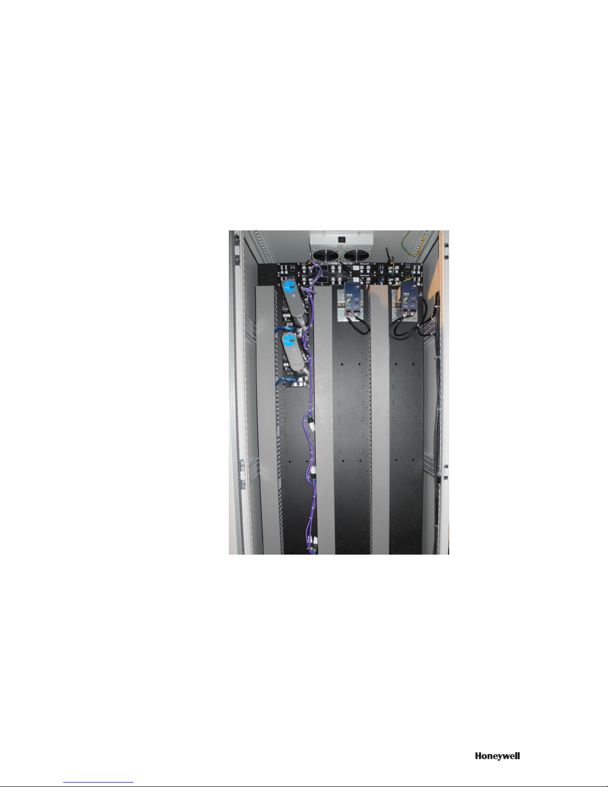
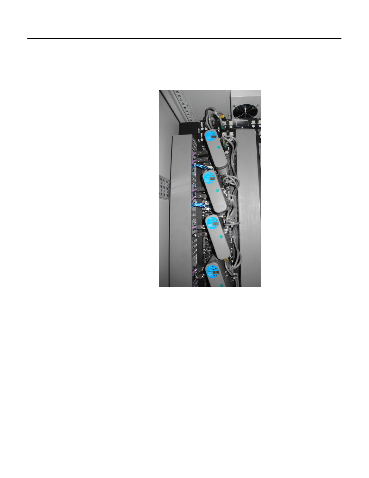
3 Mounting and segregation of wiring
This topic describes the mounting and segregation of wiring. Refer to the illustration below for more
information:
Related topics
“Cabling and wiring” on page 14
“Mounting limitations within a cabinet” on page 16
13
Page 14
3 MOUNTING AND SEGREGATION OF WIRING
3.1 Cabling and wiring
The following table describes the procedure for cabling and wiring.
1
Determine physical installation and routing. See illustration for more information:
2
Consider cable type, cable distance, and redundant cable run paths while laying cables.
3
Avoid installing cables through areas of high human traffic and high EMI/RFI.
4
Determine the maximum cable lengths and the number of drops.
5
Prepare a wiring list.
6
Maintain a blueprint with the location of wiring.
7
Plan for expansion.
8
Plan for diagnostics such as attachment spots for diagnostic tools like a protocol analyzer. See illustration
below for more information:
14 www.honeywell.com
Page 15

3 MOUNTING AND SEGREGATION OF WIRING
15
Page 16

3 MOUNTING AND SEGREGATION OF WIRING
3.2 Mounting limitations within a cabinet
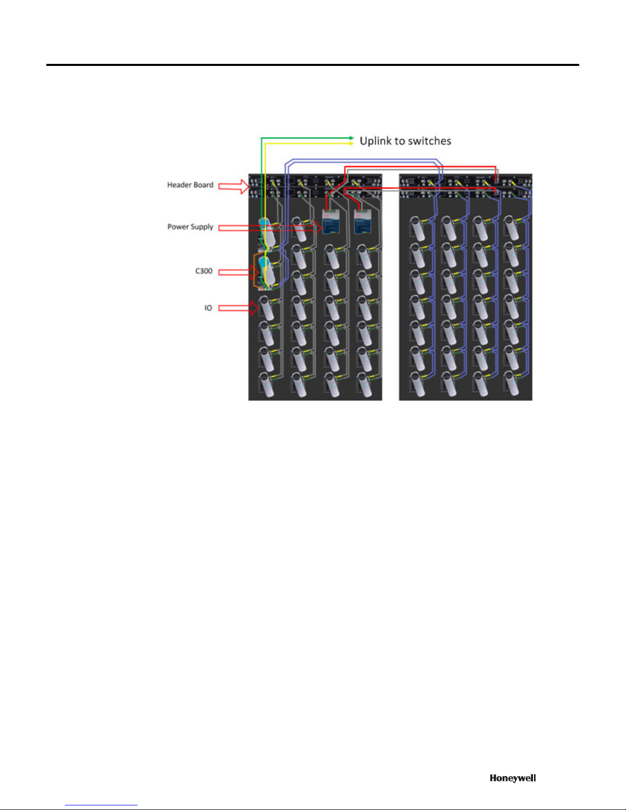
The following mounting limitations within a cabinet exist for Series 8:
• The Power System provides +24 VDC power to compatible assemblies through the header board on top of
one or more cabinets.
• The top connector of the topmost drop cable plugs into a connector on the header board. Use this cable to
connect to all the Series 8 IOTAs. These have three kinds of dimensions: six-inches (152 mm), nine inches
(229 mm) and 12 inches (305 mm).
• An extension cable is used to extend the I/O link to another cabinet side. It can plug into taps on a header
board, at the end of a header board, or at the bottom of a drop cable (although this is not normally done).
Extension cables are normally used to extend a header board to another cabinet side in a complex.
16 www.honeywell.com
Page 17

4 Bonding and grounding
This chapter provides more information about bonding and grounding
Related topics
“Cabinet safety ground connections” on page 18
“Power supply grounding considerations” on page 20
17
Page 18

4 BONDING AND GROUNDING
4.1 Cabinet safety ground connections
Adequate grounding is important for safety considerations and for reducing electromagnetic noise interference.
All earth-ground connections must be permanent and provide a continuous low impedance path to earth ground
for induced noise currents and fault currents. Refer to the following guidelines when considering the grounding
requirements of your system:
Grounding requirements
For safe operations of your equipment, a high-integrity grounding system must be installed as part of the
building's wiring system.
• An equipment ground wire must be enclosed with the circuit conductors (phase and neutral wires).
• The size of the ground conductor must be the same as, or larger, than the circuit conductors supplying the
equipment.
• The ground conductor must be securely bonded to the building-ground electrode.
• Grounding provisions must be in accordance with the NEC, CEC, and any other local codes.
• Ensure that the cabinet enclosure is connected to a protective earth ground using at least a #8 AWG solid
copper wire. There should be metal to metal contact between the grounding bus bar and the enclosure as
well as the channel. See the illustration below for more information:
The following illustration and callout table identifies typical safety ground connections in the cabinet. For
Honeywell assembled cabinets, all power and ground connections within the cabinet are made by Honeywell
manufacturing. The illustration is not to scale nor are component positions representative of actual mounting
locations within the cabinet. See illustration below for more information:
Callout Description
1 The AC safety ground bar is mounted to the cabinet frame.
2 To the cabinet front or rear AC safety ground bar if required.
3 To the cabinet complex front or rear AC safety ground bar as required.
4 To a supplementary ground connection, if required.
5 The local ground bar is mounted to the cabinet frame, if required
See illustration below for more information:
18 www.honeywell.com
Figure 1: Power and ground connections
Page 19

Figure 2: Typical safety ground connections in cabinet
4 BONDING AND GROUNDING
19
Page 20

4 BONDING AND GROUNDING
4.2 Power supply grounding considerations
AC Safety Ground System (mains ground)
The safety ground protects the plant power system, electrical equipment, and personnel from electric shock. All
metal equipment and enclosures are connected to this system through the ground wire. If insulated, the ground
wire color is normally green. The ground wire and neutral wire are connected to the mains ground rods or grid
located where the power enters the building or job area as shown in the following figure. It also describes a
typical AC power source through the mains panel with a safety ground bus and an AC safety (mains) ground
rod.
Termination of any required cable shields
The shield of the cable must be grounded.
20 www.honeywell.com
Page 21

5 Power supply selection and distribution
Series 8 system CE Compliance requires the following manufacturers and model power supplies:
Manufacturer Model number
PULS CPS20.241
MEAN WELL SDR-480P-24
Phoenix TRIO-PS/1AC/24DC/20
Refer to the corresponding manuals of each manufacturer’s for installation limitations.
Related topics
“Selecting the Power System” on page 22
“Power Distribution System” on page 23
21
Page 22

5 POWER SUPPLY SELECTION AND DISTRIBUTION
5.1 Selecting the Power System
The Power System provides +24 VDC power to compatible assemblies through the header board at the top of
one or more cabinet.
Power system parts
The power systems provide 24 VDC power to assemblies that are compatible in one or more cabinet sides. Each
power system includes the following:
• The metal piece that holds power supplies
• Two 20A Power Supply 120/240 VAC
See illustration below for more information:
22 www.honeywell.com
Page 23

5.2 Power Distribution System
The power distribution subsystem consists of the hardware listed in the following table. It distributes 24 VDC
from a power system to one or more columns of mounting plates in one or both sides of a cabinet that contains
the power system.
The following hardware requirements are prerequisites for the power distribution subsystem.
• The power system mentioned in the Selecting Power System section.
• Two header boards (51307186)
• Select power cables greater than or equal to 16AWG for AC. Maximum current of the header board is 20 A
See illustration below for more information:
5 POWER SUPPLY SELECTION AND DISTRIBUTION
Figure 3: Cabling for the power distribution subsystem
23
Page 24

5 POWER SUPPLY SELECTION AND DISTRIBUTION
24 www.honeywell.com
Page 25

6 CE Limitations
The following topics provide more information about operating conditions for components, shielded twisted
pair (STP) cables and ESD issues.
Related topics
“Operation environment and shielded wiring” on page 26
“ESD issues” on page 27
“Transient protection required” on page 28
25
Page 26

6 CE LIMITATIONS
6.1 Operation environment and shielded wiring
The operating conditions for components are as follows:
Attributes Values
Storage temperature: -40°C to +85°C (–40°F to +185°F)
Ambient temperature (T4) 0°C to +60°C (32°F to +140°F)
Relative humidity: 5% to 95% (non-condensing)
Vibration (sinosoidal): Excitation: sine-shaped with sliding frequency
Shock 15 G in 3 axes (shock duration: 11 ms)
Shielded wiring required
Ethernet cables are used in cabinets to interconnect C300 Controller IOTAs. Only a shielded twisted pair (STP)
type cable is used. The use of unshielded twisted pair (UTP) cable is not allowed.
• Frequency range: 10-150 Hz
• Loads: 10 Hz— 57 Hz: 0.075 mm
• Loads: 57 Hz-150 Hz: 1 G
• Number. of axes: 3 (x, y, z)
• Traverse rate: 1 oct/min.
26 www.honeywell.com
Page 27

6.2 ESD issues
Static electrical charges
Static electricity can influence electronic equipment, and cause equipment malfunctions or damage. The effects
may range from momentary glitches to outright failures, data loss, and intermittent failures that are difficult to
locate and correct. The situation becomes even more acute with high-resistance materials, such as carpets and
plastic seat covers, in work areas that are not environmentally controlled. Devices and techniques that can be
used to reduce electrostatic discharge include:
• An increase in the relative humidity:This may be practical in only relatively small, closed work areas.
• Conductive over-covering for shoes
• Antistatic floor surfaces: These floor surfaces have all the attributes of conventional floor surfaces, except
they are conductive to suppress static electrical build-up.
• Low-pile antistatic carpets: These carpets are conductive to suppress static electricity. Carpets are available
in a wide variety of patterns and colors, can be placed over most existing floor surfaces and some carpets.
• Antistatic grounded pads: These pads are for operator work station areas, and can be placed over most
existing floor surfaces and carpets. They are meant primarily for the immediate vicinity of the work area,
and require proper grounding.
• Avoiding synthetic materials: Avoid linoleum and synthetic carpets, and other materials that generate static.
If such floor coverings are already in place, antistatic mats can be installed on the floor near the terminals.
6 CE LIMITATIONS
27
Page 28

6 CE LIMITATIONS
6.3 Transient protection required
Why do they occur?
Transient electromagnetic interference (EMI) can be generated whenever inductive loads (such as relays,
solenoids, motor starters, or motors) are operated by hard contacts (such as pushbutton or selector switches).
The wiring guidelines are based on the assumption that you guard your system against the effects of transient
EMI by using surge-suppressors; these will suppress transient EMI at its source. Inductive loads switched by
solid-state output devices alone do not require surge-suppression. However, inductive loads of ac output
modules (that are in series or parallel with hard contacts) require surge-suppression to protect the module output
circuits as well as to suppress transient EMI.
Surge-suppressors
Surge-suppressors are usually most effective when connected at the inductive loads. They are still usable when
connected at the switching devices; however, this may be less effective, because the wires connecting the
switching devices to the inductive loads act as antennas that radiate EMI. You can see the effectiveness of a
particular suppressor by using an oscilloscope to observe the voltage waveform on the line.
28 www.honeywell.com
Page 29

7 Maintenance
Related topics
“C300 controller module and IOTA replacement” on page 30
“PGM Replacement” on page 32
“Series 8 IOTA and I/O module Replacement” on page 34
29
Page 30

7 MAINTENANCE
7.1 C300 controller module and IOTA replacement
To replace a non-redundant controller module, perform the following steps:
Prerequisites
• These procedures can only be performed while off process.
• We recommend that you proceed with extreme caution whenever replacing any component in a control
system.
• Be sure the system is offline or in a safe operating mode.
• Component replacements may also require corresponding changes in the control strategy configuration
through Control Builder, as well as downloading appropriate data to the replaced component.
• Note that all modules are keyed.
1
Loosen screws at each side of the module cover that secures the controller module to the IOTA board.
2
Carefully remove the Controller module from the IOTA board and connector.
3
Insert the new controller module onto the IOTA board making sure that the controller circuit board mates
properly with the IOTA board connector.
4
Secure the controller module to the IOTA board with two screws located at each side of the plastic cover.
5
The new controller will boot-up to ALIVE or NODB state.
6
Load firmware. Ensure that the version is the same as was running on the old controller.
7
On Control Builder, perform a Load with Contents to the controller.
To replace a non-redundant controller IOTA board, perform the following steps.
1
On the defective IOTA, loosen screws at each side of the module cover that secures the controller module to
the IOTA board.
2
Carefully remove the controller module from the IOTA board and connector.
3
Label and disconnect all cables from the IOTA board connectors, (yellow and green FTE cables, gray and
violet I/OLink cables, and Battery cable).
4
Loosen the four mounting screws only half-way that secure the IOTA board to the channel.
5
Remove completely the four mounting screws securing the IOTA board to the channel and remove the
IOTA.
6
Place screws, washers and spacers aside for reassembly.
7
Assemble screws, washers and spacers on the new IOTA board. Mount new controller IOTA board on the
channel at the same position as the old IOTA board.
8
Insert and thread the four mounting screws only half-way to attach the IOTA board to the channel. Do not
tighten.
9
Tighten the four mounting screws securing the IOTA board to the channel.
10
Set the Device Index address to the same address as the old IOTA using the three rotory FTE DEVICE
INDEX switches.
11
Connect FTE-A and FTE-B Ethernet link cables to the RJ-45 connectors on C300 IOTA board.
12
The yellow Cat5 cable connects to the FTEA connector on the IOTA.
13
The green Cat5 cable connects to the FTEB connector on the IOTA.
14
Connect I/O Link cables to IOTA board, if present.
a
Connect the gray I/O LINK cable to IOL1A and IOL1B for IOLINK 1 interface of the controller.
b
Connect the violet IOLINK cable to IOL2A and IOL2B for IOLINK 2 interface of the controller.
15
Install the two-wire twisted pair battery cables onto the Memory Hold Up connector on the left side of the
IOTA board.
30 www.honeywell.com
Page 31

7 MAINTENANCE
16
Insert the controller module onto the IOTA board making sure that the controller circuit board mates
properly with the IOTA board connector.
17
Secure the controller module to the IOTA board with two screws located at each side of the plastic cover.
18
The controller will boot-up into an Alive state or a NODB operating state.
19
In Control Builder, perform a Load with Contents to the controller.
31
Page 32

7 MAINTENANCE
7.2 PGM Replacement
CAUTION
We recommend that you proceed with extreme caution whenever replacing any component in a control system. Be
sure the system is offline or in a safe operating mode. Component replacements may also require corresponding
changes in the control strategy configuration through Control Builder, as well as downloading appropriate data to
the replaced component.
Prerequisites
• This procedure can be performed only while off process. See illustration below for more information:
To replace a non-redundant PGM:
1
Loosen screws at each side of the module cover that secures the PGM to the IOTA board.
2
Loosen the plastic screw on the front of the PGM cover. Be careful not to strip the plastic screw head.
3
Carefully remove the PGM from the IOTA board and connector.
4
Insert the new PGM onto the IOTA board making sure that the PGM circuit board mates properly with the
IOTA board connector.
5
Secure the PGM to the IOTA board with two screws located at each side of the plastic cover.
6
Using a #2 Phillips screwdriver, hand tighten the plastic screw on the front of the module cover. Be careful
not to strip the plastic screw head.
7
The new PGM boots up to Alive or NODB state.
8
Load firmware which is the same version as was running in the old PGM.
9
From Control Builder, perform a Load with Contents to the PGM.
32 www.honeywell.com
Page 33

7 MAINTENANCE
To replace a non-redundant PGM IOTA board
1
On the defective IOTA, loosen the screws at each side of the module cover that secures the PGM to the
IOTA board.
2
Loosen the plastic screw on the front of the module cover. Be careful not to strip the plastic screw head.
3
Carefully remove the PGM from the IOTA board and connector.
4
Label and disconnect all cables from the IOTA board connectors, (yellow and green FTE cables and PBLink
cables).
5
Loosen the four mounting screws only half-way that secure the IOTA board to the channel.
6
Remove the screw from the left side of the IOTA board.
7
Remove the screw from the right side of the IOTA board that connects to the COM bus bar.
8
Remove completely the four mounting screws securing the IOTA board to the channel and remove the
IOTA.
9
Place screws, washers and spacers aside for reassembly.
10
Assemble screws, washers and spacers on the new IOTA board.
11
Mount the new PGM IOTA board on the channel at the same position as the old IOTA board.
12
Insert and thread the four mounting screws only half-way to attach the IOTA board to the channel.
13
Insert and tighten the screw to the left side of the IOTA board.
14
Insert and tighten the screw to the right side of the IOTA board that connects to the COM bus bar.
15
Tighten the four mounting screws securing the IOTA board to the channel.
16
Set the Device Index Address to the same address as the old IOTA using the three rotary FTE Device
Index switches.
17
Connect the FTE-A and FTE-B Ethernet link cables to the RJ-45 connectors on the PGM IOTA board. The
yellow Cat5 cable connects to the FTEA connector on the IOTA. The green Cat5 cable connects to the
FTEB connector on the IOTA.
18
Connect the PBLink cables to the IOTA board.
19
Insert the PGM onto the IOTA board making sure that the PGM circuit board synchronises properly with the
IOTA board connector.
20
Secure the PGM to the IOTA board with two screws located at each side of the plastic cover.
21
Using a #2 Phillips screwdriver, tighten the plastic screw on the front of the module cover. Be careful not to
strip the plastic screw head.
22
The PGM boots up into an Alive state or a NODB operating state.
23
Perform a Load with Contents to the PGM.
Next steps
CAUTION
We recommend that you proceed with extreme caution whenever replacing any component in a control system. Be
sure the system is offline or in a safe operating mode. Component replacements may also require corresponding
changes in the control strategy configuration through the Control Builder; as well as downloading appropriate data
to the replaced component.
33
Page 34

7 MAINTENANCE
7.3 Series 8 IOTA and I/O module Replacement
Prerequisites
• Replacing the Series 8 IOTA, requires that the IOM is in an inactive offprocess state.
To replace a Series 8 IOTA:
1
Label and disconnect all cables from the IOTA board connectors.
2
To remove the IOTA board, it is recommended that you perform the following steps:
a
Remove the IOTA from the panel by loosening the IOTA's mounting screws only half-way one by one.
b
Completely remove the IOTA's mounting screws.
c
Place screws, washers, and spacers in a secure place for potential reuse.
3
Select the mounting location on the carrier and align the mounting holes in the IOTA with screw-hole
locations on the carrier. Ensure that the component side of IOTA is facing up.
a
When mounting either the 9 or 12 inch IOTA board, it is recommended that you secure the three
mounting screws on one side (either left or right) and then secure the other side.
Tip
Securing the four corner screws and the two middle screws may cause bowing of the board and impact the
alignment of the IOTA board to the carrier holes and is not recommended.
4
Insert the I/O module onto the IOTA board making sure that the I/O circuit board mates properly with the
IOTA board connector. Secure the module to the IOTA board with two screws located at each side of the
plastic cover.
5
The I/O module boots-up into Idle state.
6
In Control Builder, perform a Load with Contents procedure.
To replace a Series 8 I/O module:
•
You have logged onto Control Builder with sufficient security level to make control strategy changes. You
can perform the following tasks:
a
You can remove and install the Series 8 IOM under power.
b
Ensure you take ESD hazard precautions when handling the module and IOTA.
CAUTION
We recommend that you proceed with extreme caution whenever replacing any component in a control
system. Ensure the system is offline or in a safe operating mode. Component replacements may also require
corresponding changes in the control strategy configuration through Control Builder, as well as downloading
appropriate data to the replaced component.
To replace an I/O module:
1
Remove the I/O module from the IOTA board and connector.
2
Insert the new I/O module onto IOTA board making sure that the I/O circuit board mates properly with the
IOTA board connector.
3
Secure the module to the:
a
IOTA board using the two metal screws at the plastic cover.
b
Carrier with the long screw that is inserted into the hole on the face of the module's plastic cover.
c
The new I/O module boots-up to the Idle state.
4
Load firmware which is the same version as was running in the old controller.
34 www.honeywell.com
Page 35

5
In the Control Builder, perform a Load with Contents.
Results
<replace with description of results>
7 MAINTENANCE
35
Page 36

7 MAINTENANCE
36 www.honeywell.com
Page 37

8 Declaration of conformity
Please see the attached CE DOC_Series 8 R110.2.
Model Number Description Rating
8C-PCNT02 C300 Control Processor, coated 24Vdc, 320mA
8U-PCNT02 C300 Control Processor,
8C-PAIHA1 HART Analog input module,
8U-PAIHA1 HART Analog input module,
8C-PAINA1 Analog input module, coated 24Vdc, 105mA
8U-PAINA1 Analog input module, uncoated 24Vdc, 105mA
24Vdc, 320mA
uncoated
24Vdc, 110mA
coated
24Vdc, 110mA
uncoated
37
Page 38

8 DECLARATION OF CONFORMITY
Model Number Description Rating
8C-PAOHA1 HART Analog output module,
8U-PAOHA1 HART Analog output module,
8C-PAONA1 Analog output module, coated 24Vdc, 190mA
8U-PAONA1 Analog output module,
8C-PDILA1 Digital input module, coated 24Vdc, 95mA
8U-PDILA1 Digital input module, uncoated 24Vdc, 95mA
8C-PDISA1 Digital input Sequence of
8U-PDISA1 Digital input Sequence of
8C-PDIPA1 Digital input Pulse
8U-PDIPA1 Digital input Pulse
8C-PDODA1 Digital output module, coated 24Vdc,105mA
8U-PDODA1 Digital output module,
8C-PAIMA1 TC/RTD input module, coated 24Vdc, 120mA
8U-PAIMA1 TC/RTD input module,
8C-IP0102 PROFIBUS Gateway module,
R110.1 Series 8 Cabinet
Installation Instruction 35
January 2014 Honeywell
Confidential & Proprietary
8U-IP0102
8C-SHEDA1 Header board, coated 24Vdc, 20A
8U-SHEDA1 Header board, uncoated 24Vdc, 20A
8C-TCNTA1 C300 Controller IOTA, coated 24Vdc, 20A
8U-TCNTA1 C300 Controller IOTA,
8C-TAIXA1 Analog Input IOTA, coated 24Vdc
8U-TAIXA1 Analog Input IOTA, uncoated 24Vdc
8C-TAIXB1 Analog Input redundant IOTA,
8U-TAIXB1 Analog Input redundant IOTA,
8C-TAOXA1 Analog Output IOTA, coated 24Vdc
8U-TAOXA1 Analog Output IOTA, uncoated 24Vdc
8C-TAOXB1 Analog Output redundant
coated
uncoated
uncoated
Events module, coated
Events module, uncoated
Accumulation module, coated
Accumulation module,
uncoated
uncoated
uncoated
coated
PROFIBUS Gateway module,
uncoated
uncoated
coated
uncoated
IOTA, coated
24Vdc, 205mA
24Vdc, 205mA
24Vdc, 190mA
24Vdc, 95mA
24Vdc, 95mA
24Vdc, 105mA
24Vdc, 105mA
24Vdc,105mA
24Vdc, 120mA
24Vdc, 430mA
24Vdc, 430mA
24Vdc
24Vdc
24Vdc
24Vdc
38 www.honeywell.com
Page 39

Model Number Description Rating
8U-TAOXB1 Analog Output redundant
24Vdc
IOTA, uncoated
8C-TDILA1 Digital Input IOTA, coated 24Vdc
8U-TDILA1 Digital Input IOTA, uncoated 24Vdc
8C-TDILB1 Digital Input redundant IOTA,
24Vdc
coated
8U-TDILB1 Digital Input redundant IOTA,
24Vdc
uncoated
8C-TDODA1 Digital Output IOTA, coated 24Vdc
8U-TDODA1 Digital Output IOTA, uncoated 24Vdc
8C-TDODB1 Digital Output redundant
24Vdc
IOTA, coated
8U-TDODB1 Digital Output redundant
24Vdc
IOTA, uncoated
8C-TAIMA1 TC/RTD IOTA, coated 24Vdc
8U-TAIMA1 TC/RTD IOTA, uncoated 24Vdc
8C-TPOXA1 PROFIBUS GATEWAY IOTA,
24Vdc
coated
8U-TPOXA1 PROFIBUS GATEWAY IOTA,
24Vdc
uncoated
51202971-112 Combo IOLINK cable 24Vdc
CPS20.241 (PULS) AC/DC power supply module 100-240V, 6.4-2.7A,
50-60Hz;
TRIO-PS/1AC/24DC/20
AC/DC power supply module 100-240V,6-3A, 50-60Hz
(Phoenix)
SDR-480P-24 (MEAN
AC/DC power supply module 100-240V,5A, 50/60Hz
WELL)
8 DECLARATION OF CONFORMITY
39
Page 40

8 DECLARATION OF CONFORMITY
40 www.honeywell.com
Page 41

9 Conclusions
Related topics
“Conclusions” on page 42
41
Page 42

9 CONCLUSIONS
9.1 Conclusions
Refer to the following statement of Honeywell for the compliance of the CE standard:
• The SI must provide final judgment regarding the CE Conformity of the assembled cabinet
• Honeywell does not take responsibility for the CE Conformity of the assembled cabinet.
• SI responsibility is inclusive of third-party assemblies that are included within the assembled cabinet
42 www.honeywell.com
Page 43

10 Notices
Trademarks
Experion® and SafeBrowse® are registered trademarks of Honeywell International, Inc.
Other trademarks
Microsoft and SQL Server are either registered trademarks or trademarks of Microsoft Corporation in the
United States and/or other countries.
Trademarks that appear in this document are used only to the benefit of the trademark owner, with no intention
of trademark infringement.
Third-party licenses
This product may contain or be derived from materials, including software, of third parties. The third party
materials may be subject to licenses, notices, restrictions and obligations imposed by the licensor. The licenses,
notices, restrictions and obligations, if any, may be found in the materials accompanying the product, in the
documents or files accompanying such third party materials, in a file named third_party_licenses on the media
containing the product, or at http://www.honeywell.com/ps/thirdpartylicenses.
Documentation feedback
You can find the most up-to-date documents on the Honeywell Process Solutions support website at:
http://www.honeywellprocess.com/support
If you have comments about Honeywell Process Solutions documentation, send your feedback to:
hpsdocs@honeywell.com
Use this email address to provide feedback, or to report errors and omissions in the documentation. For
immediate help with a technical problem, contact your local Honeywell Technical Assistance Center (TAC).
How to report a security vulnerability
For the purpose of submission, a security vulnerability is defined as a software defect or weakness that can be
exploited to reduce the operational or security capabilities of the software.
Honeywell investigates all reports of security vulnerabilities affecting Honeywell products and services.
To report a potential security vulnerability against any Honeywell product, please follow the instructions at:
https://honeywell.com/pages/vulnerabilityreporting.aspx
Submit the requested information to Honeywell using one of the following methods:
• Send an email to security@honeywell.com.
or
• Contact your local Honeywell Technical Assistance Center (TAC) listed in the “Support” section of this
document.
43
Page 44

10 NOTICES
Support
For support, contact your local Honeywell Process Solutions Customer Contact Center (CCC). To find your
local CCC visit the website, https://www.honeywellprocess.com/en-US/contact-us/customer-support-contacts/
Pages/default.aspx.
Training classes
Honeywell holds technical training classes about Experion LX. These classes are taught by experts in the field
of process control systems. For more information about these classes, contact your Honeywell representative, or
see http://www.automationcollege.com.
44 www.honeywell.com
 Loading...