

Page 1

Experion
C300 Controller
User's Guide
EP-DCX464
R301.1
11/06
Page 2

Notices and Trademarks
Copyright 2006 by Honeywell International Inc.
Release 301.1 November 27, 2006
While this information is presented in good faith and believed to be accurate, Honeywell disclaims
the implied warranties of merchantability and fitness for a particular purpose and makes no
express warranties except as may be stated in its written agreement with and for its customers.
In no event is Honeywell liable to anyone for any indirect, special or consequential damages. The
information and specifications in this document are subject to change without notice.
Honeywell, PlantScape, Experion, and TotalPlant are registered trademarks of Honeywell
International Inc.
Other brand or product names are trademarks of their respective owners.
Honeywell International
Process Solutions
2500 West Union Hills
Phoenix, AZ 85027
1-800 343-0228
ii Experion C300 Controller User's Guide R301.1
Honeywell 11/06
Page 3

About This Document
This guide provides information that will assist you in planning and designing activities, as well as
the installation, operation, and troubleshooting of C300 Process Controllers in an Experion
system.
Release Information
Document Name Document ID
C300 Controller User's Guide - ccig EP-DCX464 301.1 11/06
References
The following list identifies all documents that may be sources of reference for material discussed
in this publication.
Document Title
Release
Number
Publication
Date
Contacts
World Wide Web
The following Honeywell web sites may be of interest to Process Solutions customers.
Honeywell Organization WWW Address (URL)
Corporate
Honeywell Process Solutions
R301.1 Experion C300 Controller User's Guide iii
11/06 Honeywell
http://www.honeywell.com
http://hpsweb.honeywell.com
Page 4

About This Document
Contacts
Telephone
Contact us by telephone at the numbers listed below.
Location Organization Phone
United States
and Canada
Europe Honeywell TAC-EMEA +32-2-728-2704
Pacific
India
Korea
People’s
Republic of
China
Singapore
Taiwan
Japan
Elsewhere
Honeywell IAC Solution
Support Center
Honeywell Global TAC Pacific
Honeywell Global TAC India
Honeywell Global TAC Korea
Honeywell Global TAC China
Honeywell Global TAC South East Asia
Honeywell Global TAC Taiwan
Honeywell Global TAC Japan
Call your nearest
Honeywell office.
1-800-822-7673
1300-300-4822
(toll free within Australia)
+61-8-9362-9559
(outside Australia)
+91-20-2682-2458
+82-2-799-6317
+86-10-8458-3280 ext. 361
+65-6580-3500
+886-7-323-5900
+81-3-5440-1303
iv Experion C300 Controller User's Guide R301.1
Honeywell 11/06
Page 5
About This Document
Symbol Definitions
Symbol Definitions
The following table lists those symbols used in this document to denote certain conditions.
Symbol Definition
CAUTION
ATTENTION: Identifies information that requires special
consideration.
TIP: Identifies advice or hints for the user, often in terms of
performing a task.
REFERENCE -EXTERNAL: Identifies an additional source of
information outside of the bookset.
REFERENCE - INTERNAL: Identifies an additional source of
information within the bookset.
Indicates a situation which, if not avoided, may result in equipment
or work (data) on the system being damaged or lost, or may result in
the inability to properly operate the process.
CAUTION: Indicates a potentially hazardous situation which, if not
avoided, may result in minor or moderate injury. It may also be used
to alert against unsafe practices.
CAUTION symbol on the equipment refers the user to the product
manual for additional information. The symbol appears next to
required information in the manual.
WARNING: Indicates a potentially hazardous situation, which, if not
avoided, could result in serious injury or death.
WARNING symbol on the equipment refers the user to the product
manual for additional information. The symbol appears next to
required information in the manual.
R301.1 Experion C300 Controller User's Guide v
11/06 Honeywell
Page 6
About This Document
Symbol Definitions
Symbol Definition
WARNING, Risk of electrical shock: Potential shock hazard where
HAZARDOUS LIVE voltages greater than 30 Vrms, 42.4 Vpeak, or
60 VDC may be accessible.
ESD HAZARD: Danger of an electro-static discharge to which
equipment may be sensitive. Observe precautions for handling
electrostatic sensitive devices.
Protective Earth (PE) terminal: Provided for connection of the
protective earth (green or green/yellow) supply system conductor.
Functional earth terminal: Used for non-safety purposes such as
noise immunity improvement. NOTE: This connection shall be
bonded to Protective Earth at the source of supply in accordance
with national local electrical code requirements.
Earth Ground: Functional earth connection. NOTE: This
connection shall be bonded to Protective Earth at the source of
supply in accordance with national and local electrical code
requirements.
Chassis Ground: Identifies a connection to the chassis or frame of
the equipment shall be bonded to Protective Earth at the source of
supply in accordance with national and local electrical code
requirements.
vi Experion C300 Controller User's Guide R301.1
Honeywell 11/06
Page 7

Contents
ABOUT THIS GUIDE ..............................................................................1
Introduction ................................................................................................................ 1
Intended audience..................................................................................................................1
Prerequisite skills ...................................................................................................................1
Online documentation reference ............................................................................................1
Locating related documentation .............................................................................................2
C300 CONTROLLER PURPOSE............................................................3
C300 Controller and C200 Controller comparison .................................................3
Getting started............................................................................................................ 5
What task do you want to perform?........................................................................................5
C300 CONTROLLER PLANNING AND DESIGN ...................................7
Review Experion system capabilities ...................................................................... 7
Control Hardware Planning Guide ........................................................................... 7
Series C control hardware ........................................................................................ 8
Series C form factor ...............................................................................................................8
C300 Controller ....................................................................................................................10
C300 Controller execution environments .............................................................................11
I/O modules supported by the C300 Controller ....................................................................12
Identify C300 Controller components.................................................................... 13
C300 Controller performance data......................................................................... 15
Control network considerations............................................................................. 16
C300 Interface to C200 Controllers and ControlNet using FTEB .........................................16
C300 Peer communication with Experion nodes..................................................................16
C300 connections with Rockwell PLC devices.....................................................................17
C300 connections to the Control Firewall.............................................................................17
C300 CONTROLLER INSTALLATION AND UPGRADES ...................19
Pre-installation considerations ..............................................................................19
Installation declarations........................................................................................................19
Series C control hardware installation requirements ............................................................20
R301.1 Experion C300 Controller User's Guide vii
11/06 Honeywell
Page 8

Contents
Series C Power System............................................................................................20
Controller Memory Backup.................................................................................................. 21
C300 Controller installation.....................................................................................21
C300 Controller assembly ................................................................................................... 21
To install a C300 Controller ................................................................................................. 24
C300 Secondary Controller Installation ............................................................................... 27
To install a partner secondary C300 Controller ................................................................... 28
CF9 Control Firewall.................................................................................................30
9-Port Control Firewall (CF9)............................................................................................... 30
Series C I/O modules installation ...........................................................................31
Series C FIM installation ..........................................................................................31
Upgrading C300 Controller Firmware.....................................................................31
Using the Controller Migration Wizard................................................................................. 31
C300 Controller behavior during firmware upgrade and timeout ......................................... 31
C300 CONTROLLER CONFIGURATION ............................................ 33
Configuration overview............................................................................................34
Configuration Studio............................................................................................................34
Define and add assets in your enterprise model ................................................................. 34
FTE system configuration.................................................................................................... 34
Specifying a Time Server .................................................................................................... 35
C300 Controller Device Index ............................................................................................. 35
Create C300 Controller and CEE function blocks.................................................36
To configure a C300 Controller block .................................................................................. 36
Configure CEEC300 block .......................................................................................42
To configure a CEEC300 function block.............................................................................. 42
Configure a Secondary C300 Controller block......................................................46
To configure a Secondary C300 Controller block ................................................................ 47
Convert a non-redundant C300 Controller to a redundant controller.................49
To convert a non-redundant C300 Controller to a Redundant controller ............................. 49
Convert a redundant C300 Controller to a non-redundant controller.................51
To convert a redundant C300 Controller to a non-redundant controller .............................. 51
Configure IOLINK function blocks..........................................................................52
To configure IOLINK blocks ................................................................................................ 53
Import/export C300 Controller configuration ........................................................55
Reset Device Index and IP address of a controller...............................................55
viii Experion C300 Controller User's Guide R301.1
Honeywell 11/06
Page 9

Contents
Create a Control Module ......................................................................................... 57
To create and save a Control Module. .................................................................................58
Assign Control Modules and IOMs to a CEEC300 block ..................................... 60
To assign Control Modules and IOMs to a CEE...................................................................61
Copy Control Modules............................................................................................. 66
To copy an existing Control Module .....................................................................................66
Assign I/O Modules to C300 IOLINK blocks.......................................................... 68
To assign Series C IO Modules and Process Manager IOMs to IOLINK blocks ..................68
Add an I/O Channel to a Control Module............................................................... 73
To add IO Channel blocks to a Control Module chart...........................................................74
C300 CONFIGURATION FORM REFERENCE ....................................77
C300 Controller Block ............................................................................................. 77
Main tab ...............................................................................................................................77
Redundancy tab ...................................................................................................................79
System Time tab ..................................................................................................................82
Statistics tab.........................................................................................................................84
Peer Connections tab...........................................................................................................86
Hardware Information tab.....................................................................................................87
FTE tab ................................................................................................................................88
UTP/TCP tab........................................................................................................................92
IP/ICMP tab..........................................................................................................................95
Soft Failures tab ...................................................................................................................98
QVCS tab...........................................................................................................................100
Server History tab ..............................................................................................................100
Server Displays tab ............................................................................................................102
Control Confirmation tab ....................................................................................................104
Identification tab .................................................................................................................104
Secondary C300 Block .......................................................................................... 106
Main Tab ............................................................................................................................106
Redundancy Tab................................................................................................................106
CEEC300 Function Block ......................................................................................106
Main Tab ............................................................................................................................106
Peer Configuration tab .......................................................................................................109
Statistics tab.......................................................................................................................110
CPU Loading Tab...............................................................................................................114
CPU Overruns tab..............................................................................................................114
Memory tab ........................................................................................................................115
Peer Communications tab..................................................................................................117
Display Communications tab..............................................................................................118
Block Types Info tab...........................................................................................................119
R301.1 Experion C300 Controller User's Guide ix
11/06 Honeywell
Page 10

Contents
Custom Types Info tab ...................................................................................................... 120
QVCS tab .......................................................................................................................... 121
Server History tab.............................................................................................................. 121
Server Displays tab ........................................................................................................... 121
Control Confirmation tab ................................................................................................... 121
Identification tab ................................................................................................................ 121
IOLINK Block...........................................................................................................122
Main Tab ........................................................................................................................... 122
Memory Stats tab .............................................................................................................. 124
Statistics tab...................................................................................................................... 125
I/O Link Status tab............................................................................................................. 133
I/O Status Summary tab .................................................................................................... 136
IOTA Summary tabs.......................................................................................................... 137
QVCS tab .......................................................................................................................... 139
Server History tab.............................................................................................................. 139
Server Displays tab ........................................................................................................... 140
Control Confirmation tab ................................................................................................... 140
Identification tab ................................................................................................................ 140
LOAD C300 CONTROLLER CONFIGURATION ............................... 141
About load operations ...........................................................................................141
Loaded versus project database versions ......................................................................... 141
Load initiation and load dialog box .................................................................................... 142
Load action with compare parameters function ................................................................. 143
Load options for server history and server displays configuration..................................... 143
Initial load order guidelines...................................................................................144
Component deletion considerations .................................................................................. 145
Load components from Project ............................................................................145
Loading C300 Controller ................................................................................................... 145
To load a C300 Controller block and its associated blocks ............................................... 145
Loading IOLINK................................................................................................................. 148
To load a IOLINK block ..................................................................................................... 149
Loading CEEC300............................................................................................................. 151
To load a CEEC300 block ................................................................................................. 151
Loading IOMs and CMs..................................................................................................... 153
Load With Contents command..............................................................................154
Reloading components from project....................................................................154
Upload to the Monitoring database ......................................................................156
C300 CONTROLLER OPERATION ................................................... 157
x Experion C300 Controller User's Guide R301.1
Honeywell 11/06
Page 11

Contents
C300 Controller start up ........................................................................................157
C300 Controller states in boot mode..................................................................................160
C300 Controller states in application mode........................................................................161
C300 faceplate indicators/displays ...................................................................... 162
Power and Status LEDs .....................................................................................................163
Faceplate display information.............................................................................................164
FTE activity LEDs...............................................................................................................166
C300 faceplate display indications ......................................................................167
Control Builder block icon descriptions.............................................................. 168
Activate C300 Controller’s CEE............................................................................ 172
Initial activation order guidelines ........................................................................................172
Activating the CEE .............................................................................................................172
Setting the CEE inactive.....................................................................................................174
CEE Icon states in the Monitoring tab ................................................................................176
Initiating C300 Controller Shutdown.................................................................... 176
Initiating Synchronization command................................................................... 177
Prerequisites ......................................................................................................................177
Commanding synchronization............................................................................................177
Disable Synchronization command ..................................................................... 178
Prerequisites ......................................................................................................................178
To Disable Synchronization................................................................................................178
Initiating Become Primary command................................................................... 178
Prerequisites ......................................................................................................................178
Commanding Become Primary ..........................................................................................179
Initiating Switchover command............................................................................ 179
Prerequisites ......................................................................................................................179
Commanding a switchover.................................................................................................179
Using Station displays .......................................................................................... 180
C300 Controller Point Detail displays.................................................................................180
Controller Detail displays....................................................................................................180
Event and Alarm summary displays ...................................................................................180
FTE Status display .............................................................................................................180
Viewing controller operation and status in Control Builder.............................. 181
C300 operating behaviors ..................................................................................... 183
Time management in the C300 Controller..........................................................................183
Hardware Watchdog Timer ................................................................................................184
Critical Task Health Monitor ...............................................................................................184
C300 Controller overload conditions ..................................................................................185
R301.1 Experion C300 Controller User's Guide xi
11/06 Honeywell
Page 12

Contents
C300 REDUNDANCY OPERATION................................................... 187
Description..............................................................................................................187
Redundancy configuration restrictions ...............................................................188
C300 Controller Device Index ........................................................................................... 188
IOLINK interface considerations........................................................................................ 188
Series C FIM restrictions ................................................................................................... 188
Partner (controller) compatibility..........................................................................189
Redundancy compatibility parameter - RDNCMPT ........................................................... 190
Synchronization states ..........................................................................................191
Standby state .................................................................................................................... 192
Redundancy parameters........................................................................................193
Enable Synchronization – ENBLSYNCCMD ..................................................................... 194
Disable Synchronization – DSBLSYNCCMD .................................................................... 194
Enable Standby – ENBLSTBYCMD .................................................................................. 194
Auto-Synchronization State – RDNAUTOSYNC ............................................................... 194
Inhibit Sync Reason – RDNINHIBITSYNC ........................................................................ 195
Initial Sync Progress – RDNSYNCPROG ......................................................................... 196
Maximum Initial Synchronization Time – RDNISTIMEMAX............................................... 196
Last Synchronization Time – SYNCTIMEBEG .................................................................. 197
Last Lost of Sync Time – SYNCTIMEEND........................................................................ 197
Redundancy Traffic ........................................................................................................... 197
Redundancy Delay ............................................................................................................ 197
Conditions that result in loss of sync ................................................................................. 197
Conditions that do not result in loss of sync ...................................................................... 198
Switchover...............................................................................................................198
Initiate Switchover – SWITCHCMD ................................................................................... 198
Max Switchover Time – RDNSOTIMEMAX ....................................................................... 198
Conditions that result in switchover ................................................................................... 199
Conditions that do not result in a switchover ..................................................................... 199
Become Primary command – BECMPRICMD................................................................... 200
Redundancy history ...............................................................................................200
C300 Redundancy-related notifications...............................................................200
Redundancy Link Status – RDNLINKFAILED ................................................................... 204
OPM Status – RDNOPMSTATUS ..................................................................................... 204
On-process Migration of C300 Controller ............................................................208
‘Go-Back to Idle’ option ..................................................................................................... 208
Controller redundancy specifications..................................................................209
C300 CONTROLLER MAINTENANCE .............................................. 211
xii Experion C300 Controller User's Guide R301.1
Honeywell 11/06
Page 13

Contents
C300 Controller module and IOTA replacement ................................................. 211
To replace a non-redundant controller module...................................................................211
To replace a redundant or secondary controller module ....................................................212
To replace a non-redundant controller IOTA board............................................................213
To replace a redundant or secondary controller IOTA .......................................................214
C300 CONTROLLER TROUBLESHOOTING .....................................217
Overview ................................................................................................................. 217
What to do when faults occur............................................................................... 217
Initial checks........................................................................................................... 218
Checking Control Builder error code reference ..................................................................218
Checking faceplate display and LEDs................................................................................218
Using CTools to capture diagnostic data............................................................................219
Viewing flash log ................................................................................................................220
Viewing release information log .........................................................................................220
Checking server point build log ..........................................................................................220
Checking server point build error log..................................................................................220
Checking error log..............................................................................................................220
Fixing common problems ..................................................................................... 220
Loss of power.....................................................................................................................221
Power-On Self Test (POST) does not complete.................................................................221
Controller display shows –bp– or –ts– ...............................................................................222
Controller display shows –SF– alternating with OK/BKUP.................................................222
One or both FTE LEDs are RED ........................................................................................223
Controller does not synchronize with backup.....................................................................224
Fatal ECC error ..................................................................................................................225
Display shows FAIL............................................................................................................226
Isolated (lonely) Node ........................................................................................................226
Duplicate Device Index setting ...........................................................................................227
Device Index value is zero upon power up.........................................................................228
C300 Controller soft failures................................................................................. 228
IOLINK block soft failures .....................................................................................232
Additional status and fault messages ................................................................. 235
Redundancy-related notifications .......................................................................................235
OPM-related notifications – RDNOPMSTATUS parmaeter................................................235
Online diagnostics................................................................................................. 235
Fault classifications............................................................................................... 235
Hard/Severe Failures .........................................................................................................237
Soft Failures .......................................................................................................................238
Installation-Startup Failures................................................................................................239
R301.1 Experion C300 Controller User's Guide xiii
11/06 Honeywell
Page 14

Contents
Hardware Watchdog Timer Expired .................................................................................. 239
Communications Faults..................................................................................................... 240
Communication and system time startup fault scenarios .................................240
Non-redundant C300 Controller with no Memory Retention.............................................. 240
Non-redundant C300 Controller with Memory Retention................................................... 242
Redundant Primary C300 Controller with no Memory Retention....................................... 243
Redundant Primary C300 Controller with Memory Retention............................................ 245
Secondary C300 Controller with no Memory Retention..................................................... 246
Secondary C300 Controller with Memory Retention.......................................................... 248
Notes:................................................................................................................................ 249
Gathering information for reporting problems to Honeywell ............................250
Getting further assistance.....................................................................................251
Other troubleshooting sources .......................................................................................... 251
Guidelines for requesting support...................................................................................... 253
xiv Experion C300 Controller User's Guide R301.1
Honeywell 11/06
Page 15

Contents
Tables
Tables
Table 1 Series A I/O Modules supported by C300 Controller ......................................12
Table 2 Series C Hardware components...................................................................... 13
Table 3 C300 Controller IOTA Board Connector Summary ......................................... 23
Table 4 Initial Load Order Guidelines ......................................................................... 144
Table 5 C300 Controller Startup and Power On Self Test routine ............................. 158
Table 6 Controller in Boot mode.................................................................................. 160
Table 7 C300 Controller in Application mode............................................................. 161
Table 8 C300 Controller LED indications ...................................................................163
Table 9 C300 Controller faceplate display indications ............................................... 165
Table 10 FTE Activity LED Indications ....................................................................... 166
Table 11 Display indications when controller is in application mode .........................167
Table 12 Display indications when controller is in boot mode.................................... 168
Table 13 C300 Controller icon indications in Control Builder..................................... 169
Table 14 Redundancy-Related Notifications .............................................................. 201
Table 15 OPM-Related Notifications ........................................................................... 204
Table 16 C300 Controller Soft Failures ...................................................................... 229
Table 17 IOLINK Block Soft Failures.......................................................................... 232
Table 18 C300 Fault Classifications and Possible Causes ........................................236
R301.1 Experion C300 Controller User's Guide xv
11/06 Honeywell
Page 16

Contents
Figures
Figures
Figure 1 Series C form factor example ...........................................................................9
Figure 2 Redundant C300 Controller block in the Project tree .....................................11
Figure 3 C300 Controller IOTA Board Features ...........................................................22
Figure 4 Control Module chart with an AICHANNEL block...........................................75
Figure 5 Sample Load Dialog......................................................................................143
Figure 6 C300 Controller Startup and Boot Mode indications .....................................160
Figure 7 C300 Controller faceplate features ...............................................................163
Figure 8 Control Builder Monitoring tab ......................................................................181
Figure 9 C300 Controller configuration form...............................................................182
Figure 10 C300 Controller synchronization states ......................................................192
Figure 11 C300 Controller Block Redundancy tab.......................................................193
Figure 12 Soft Failures tab in Control Builder .............................................................229
xvi Experion C300 Controller User's Guide R301.1
Honeywell 11/06
Page 17

Introduction
This guide provides information that will assist you in planning and designing activities,
as well as the installation, operation, and troubleshooting of C300 Process Controllers in
an Experion system.
Intended audience
This guide is intended for the following users:
• Persons responsible for system planning, initial hardware installation, and control
strategy configuration
• Operators who help to maintain control system operations on a day-by-day basis
• Service persons responsible for routine maintenance of control hardware and who
also diagnose and repair faults.
Prerequisite skills
It is assumed that you should have some knowledge of Experion control systems and
experience of working in a Microsoft Windows environment.
About this guide
Online documentation reference
Knowledge Builder is the online documentation library for the Experion system. It is
provided on a compact disc and can be installed on a suitable personal computer. If you
are using a printed copy of the C300 Controller Guide, we recommend that you install
Knowledge Builder to take advantage of its online search and reference capabilities.
Other resources and guides in Knowledge Builder provide this same information for
other Experion control hardware, such as Process Manager I/O, Series C I/O, and Series
A Chassis I/O. See Locating related documentation
documents.
R301.1 Experion C300 Controller User's Guide 1
11/06 Honeywell
for a partial listing of these
Page 18

Introduction
Locating related documentation
Locating related documentation
Listed here are Knowledge Builder documents that contain general information for
planning and implementing control hardware and network communications in your
Experion system:
Control Hardware Planning Guide - Provides general information to assist you in
planning and design of control hardware in an Experion system. Control hardware
includes C200 Controllers, Series A Chassis I/O and FIMs, also, all I/O families, (except
Series C I/O). It includes some supervisory network considerations for general reference.
Series C I/O Module User’s Guide - The guide contains planning and implementation
information for Series C I/O modules. Module types include: AI, AO, AIMUX, DI and
DO.
Series C Fieldbus Interface Module User’s Guide - Provides planning and
implementation guide for the Series C Fieldbus Interface Module4.
Control Firewall User’s Guide – A hardware and installation reference about the FTE
switch component for Series C control hardware.
Fault Tolerant Ethernet Overview and Implementation Guide - Provides basic
installation instructions and configuration requirements for a Fault Tolerant Ethernet
(FTE) network and its components.
Fault Tolerant Ethernet Installation and Service Guide - Contains instructions for
installing and configuring a Fault Tolerant Ethernet (FTE) node. The guide includes
troubleshooting and service information for an FTE node.
Fault Tolerant Ethernet Bridge User Guide - Provides information for implementing a
Fault Tolerant Ethernet supervisory network through the FTE Bridge module. It
includes module installation, configuration, operation and service data.
Process Manager I/O Troubleshooting and Maintenance Guide - Guide features
notification messages (soft fail codes and hard fail codes), service procedures and parts
lists for PMIO I/O control hardware.
2 Experion C300 Controller User's Guide R301.1
Honeywell 11/06
Page 19
C300 Controller Purpose
This section provides a quick comparison of C200 and C300 Controller features and
reference to topics in this book for a given task related to using the C300 Controller with
the Experion system. Click on the topic to view it.
Topic
C300 Controller and C200 Controller comparison
Getting started task list
C300 Controller and C200 Controller comparison
If you are familiar with the operation and capabilities of the C200 chassis-based process
controller, then you can readily appreciate the design improvements and greater
capabilities for process control that the C300 Controller provides. The following table is
a listing that compares design features and operational improvements of the C300
Controller with the C200 controller.
Controller Feature Comparison
Form Factor
Memory (RAM)
Redundancy
I/O Link Interface C200 – An I/O Link Interface plug-in Module (IOLINK) installed
R301.1 Experion C300 Controller User's Guide 3
11/06 Honeywell
C200 – Chassis-based controller with plug-in modules for
Control Processor, I/O Link Interface, Redundancy, FTE
interface, Fieldbus, other I/O and control modules.
C300 – A single control module that plugs into an Input Output
Terminal Assembly (IOTA). Control module functions include
a Control processor, two I/O Link interfaces, Redundancy
functions, and FTE interfaces.
C200 – 4MB User Memory
C300 – 16MB User Memory
C200 –Two identically-equipped controller chassis that contain
two Redundancy Modules (RM) provide controller redundancy.
C300 – Controller redundancy function is built in. A second
C300 Controller and redundancy cable is all that is required for
redundant controller operation. (No RMs)
in the controller chassis is required to connect PMIO I/O to the
Page 20
C300 Controller and C200 Controller comparison
Locating related documentation
Controller Feature Comparison
controller CPM.
C300 – Two I/O Link interfaces are built in to the controller.
Each I/O Link can connect with either PMIO I/O or Series C I/O
modules.
Communications
Interface to supervisory
network
Peer-to-Peer
Connections
Function Blocks C200 and C300 – Both Controllers use the same standard
Engineering Tools C200 and C300 – Both controllers use the same engineering
C200 – Ethernet or Fault Tolerant Ethernet plug-in modules
are needed to connect to respective Ethernet and FTE
communication networks. ControlNet Interface plug-in module
is needed to connect with other ControlNet nodes.
C300 – Ethernet interface is built into the controller and
supports both Ethernet and redundant FTE communications.
No ControlNet interface.
C200 – Ethernet or Fault Tolerant Ethernet Bridge plug-in
modules are needed to connect to respective Ethernet and
FTE networks. ControlNet Interface plug-in module is needed
to connect with other ControlNet nodes.
C300 – Ethernet interface is built into the controller and
supports both Ethernet and redundant FTE communications.
No ControlNet interface. C300 connection to C200 controller
is made through an FTE Bridge module installed in the C200
chassis.
Experion function block types for control strategy execution.
There are some exceptions.
tools utilities and applications for maintenance tasks (except
NTools). C300 uses CTools engineering utility.
4 Experion C300 Controller User's Guide R301.1
Honeywell 11/06
Page 21
Getting started
What task do you want to perform?
Getting started
The following table lists some of the tasks covered in this document that are related to
implementing a C300 Controller in your Experion R300 system or later. If you are
viewing this document online, just click the reference to jump to the topic in this
document.
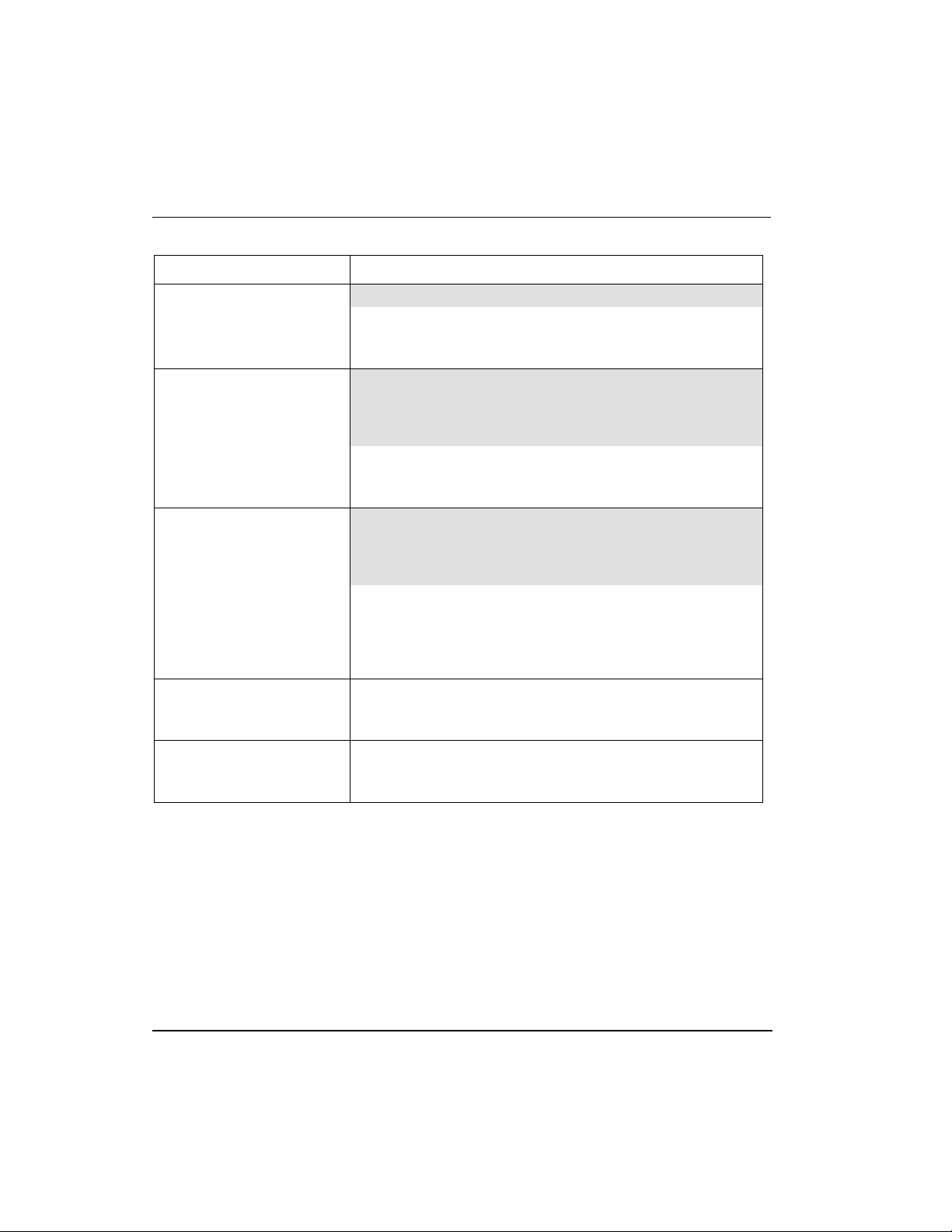
What task do you want to perform?
If You Want to . . . Then, See This Topic . . .
Plan and design a C300 Controller installation C300 Controller Planning and Design
Know more about C300 hardware Series C Control Hardware
Identify C300 Controller components
Know more about C300 Controller
performance
Install and wire C300 Controller hardware C300 Controller installation
Upgrade Controller firmware Upgrading C300 Controller firmware
Create C300 Controller and CEE function
blocks
Configure CEE function blocks Configure CEEC300 block
Configure IOLINK function blocks Configure IOLINK function blocks
Configure a Secondary C300 Controller Configure a Secondary C300 Controller block
Convert a Non-redundant C300 Controller to a
redundant controller
Convert a redundant C300 Controller to a Nonredundant controller
Reset Controller Device Index
View configuration parameter descriptions C300 Configuration Form Reference
Load function blocks to C300 components Load C300 Controller Configuration
Reload components from Project Reloading components from Project
C300 Controller performance data
C300 Controller Configuration
Convert a non-redundant C300 Controller to a
redundant controller
Convert a redundant C300 Controller to a Nonredundant controller
Reset Device Index and IP address of a
controller
Review C300 Controller start up routines C300 Controller start up
R301.1 Experion C300 Controller User's Guide 5
11/06 Honeywell
Page 22
Getting started
What task do you want to perform?
If You Want to . . . Then, See This Topic . . .
Review C300 Controller operating indications C300 Faceplate indicators/displays
Shutdown a C300 Controller C300 Controller shutdown
Activate the Controller’s CEE Activate C300 Controller’s CEE
View Controller operations Viewing controller operation and status
Interacting through Station displays
Review C300 Controller redundancy
functionality
Review C300 Controller maintenance and
replacement procedures
Investigate a cause of a problem C300 Controller Troubleshooting
Install and wire C300 Controller hardware C300 Controller installation
C300 redundancy operation
C300 Controller Maintenance
6 Experion C300 Controller User's Guide R301.1
Honeywell 11/06
Page 23
C300 Controller Planning and Design
This section includes information about system planning and design of the C300
Controller. The following topics are presented here. Click on the topic to view it.
Topic
Review Experion system capabilities
Control Hardware Planning Guide
Series C control hardware
C300 Controller
Identifying C300 Controller components
C300 Controller performance data
Control network considerations
Review Experion system capabilities
Read the Overview document in Knowledge Builder so that you understand the basic
concepts and terminology, and appreciate the capabilities of Experion.
Complement the information in this document with the data in the Server and Client
Planning Guide to cover all aspects of an Experion installation.
REFERENCE - INTERNAL
For planning and design topics for Experion servers and clients as well as
information about adding third-party controllers, see the Server and Client
Planning Guide.
Control Hardware Planning Guide
Refer to the Control Hardware Planning Guide in Knowledge Builder for a general
discussion of planning activities for Experion Control hardware that covers:
• Initial planning and design
• Control network considerations
• Control hardware configuration
R301.1 Experion C300 Controller User's Guide 7
11/06 Honeywell
Page 24

Series C control hardware
Series C form factor
• Site selection and planning
• Control processing considerations
• Application licensing considerations
Series C control hardware
Series C control hardware consists of the following system components:
• C300 Controller is a distributed process controller and I/O gateway for the
Experion system. With only a few exceptions, the C300 Controller fully supports
configuration, load and execution of the standard function blocks supported in
previous Experion releases, (R210).
• Series C Input/Output Modules that feature HART-capable AI and AO modules,
and a low level Mux AI module. Digital input modules that support high voltage AC
and 24V DC inputs, and a Digital Output module that provides 24 VDC.
• The Series C Fieldbus Interface Module, (Series C FIM) which is designed to
complement the C300 Controller and support Fault Tolerant Ethernet (FTE)
communications within Experion R300 systems or later.
• A 9-port Control Firewall, (CF9) provides eight FTE interface connections for
C300 Controllers and Series C FIMs within a control cabinet and one uplink to the
supervisory FTE communications network.
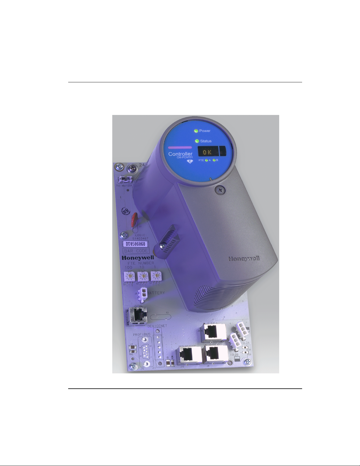
Series C form factor
All Series C control hardware is constructed using the same form factor; that is, the C300
Controller modules, Series C I/O modules, Control Firewall modules, and Series C FIMs
all mount on their associated Input Output Termination Assemblies (IOTAs), which are
installed on carrier hardware specifically designed to support Series C hardware
installation. The module’s circuit board assemblies are housed in a plastic case with a
round faceplate that identifies the module type and model number along with status
LEDs and a four-character alphanumeric display. The IOTA contains connectors that
accept the associated control module and the various I/O connectors for cables that
connect to other Series C control hardware. Figure 1 shows an example of the design.
8 Experion C300 Controller User's Guide R301.1
Honeywell 11/06
Page 25
Series C control hardware
Series C form factor
Figure 1 Series C form factor example
R301.1 Experion C300 Controller User's Guide 9
11/06 Honeywell
Page 26

Series C control hardware
C300 Controller
REFERENCE - INTERNAL
For more details about Series C I/O and FIM modules refer to the Series C
I/O User’s Guide and the Series C Fieldbus Interface Module User’s Guide.
C300 Controller
The C300 Controller is constructed using the Series C form factor that employs an Input
Output Termination Assembly (IOTA) and an electronics module which mounts and
connects to the IOTA. One C300 Controller contains all of the control functionality and
most of the communications functions that previously required a C200 controller chassis
filled with plug-in modules. This smaller controller footprint and ease of installation,
combined with enhanced functionality that is built upon C200 performance, provides
greater value for Experion users.
The C300 Controller fully supports configuration, load and execution of the standard
function blocks supported in previous Experion releases, (R210). Note that there are a
few exceptions defined below.
Exceptions
The following function blocks are not supported by the C300 Controller in Experion
Release 300.1:
• The LIOM function block set.
• CAB related function blocks other than the Custom Data Block (CDB)
• The REEOUT Function Block – an ACE only function block
• Series A IOM function blocks not listed in Table 1 Series A I/O Modules supported
by C300 Controller.
C300 Controller redundancy
The C300 Controller may operate in both non-redundant and redundant configurations.
Redundant operation requires a second identical controller and connecting cables, which
is the typical configuration.
C300 Controller block
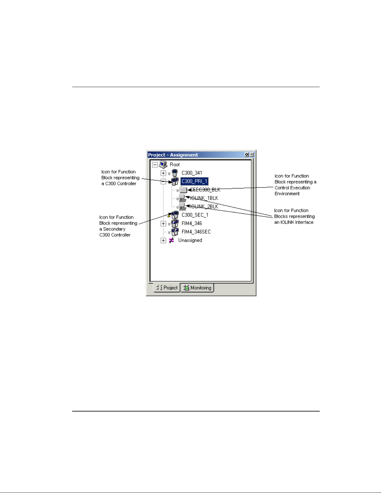
When a C300 Controller block is added to the Project tree in Control Builder, a graphic
representation of a controller module and its resident function blocks appears as shown in
Figure 2. The function blocks that are contained in the controller support multiple
execution environments. A Control Execution Environment block (CEEC300) and two
10 Experion C300 Controller User's Guide R301.1
Honeywell 11/06
Page 27
Series C control hardware
C300 Controller execution environments
IOLINK blocks are contained in the controller and appear under the controller. When the
controller block is configured as redundant, the secondary controller block is added in the
Project tree.
Figure 2 Redundant C300 Controller block in the Project tree
C300 Controller execution environments
The C300 Controller supports three Execution Environment (EE) function blocks. One is
the Control EE block, (CEEC300) which is essentially the same block found in the C200
controller. The other two are I/O Link blocks, (IOLINK) similar to the IOLINK block
available with the C200. The IOLINK blocks in the C300 support connection and
communication with PMIO I/O control hardware, (as with the IO Link Interface Module
in C200 controllers), but also support connection and communications with all Series C
I/O modules.
CEE function block
The Control Execution Environment (CEEC300) block is a function block which is
similar to the CEE blocks in the C200 and ACE controllers and uses the same library of
R301.1 Experion C300 Controller User's Guide 11
11/06 Honeywell
Page 28

Series C control hardware
I/O modules supported by the C300 Controller
block types. The CEEC300 block provides an execution and scheduling environment in
which user-configured Control Modules (CMs) and Sequential Control Modules (SCMs)
execute. This block also provides a peer-to-peer communications layer used to
communicate between other controllers. The CEEC300 block supports communication
and containment of Series A I/O module and channel blocks.
IOLink function blocks
Two IOLINK function blocks, which represent the 2 physical IO links on the C300
Controller IOTA, provide the I/O Link interface to support communications with PMIO
I/O module card files and/or Series C I/O modules. Each IOLINK is configured to
support either PMIO I/O or Series C I/O modules, or ‘No Link’ if no I/O control is
required. Each IOLINK supports redundant and non-redundant communications and
contains the same functionality as the IOLINK blocks used in the C200 controller and
IOLIM interface.
I/O modules supported by the C300 Controller
The C300 Controller is connected to the associated I/O hardware by a pair of I/O Link
Interface cables. All Series C I/O modules and all PMIO I/O modules qualified for use in
Experion are supported by the C300 Controller.
For a list of the supported I/O modules, see,
• Planning Your Input/Output Processor (IOP) Cards for a list of supported IO
modules.
• Viewing supported Series C I/O modules for a listing of available Series C IO
modules.
A number of Series A I/O chassis-based modules have been qualified for support with
the C300 Controller. Some of these modules are implemented in a Control Component
Library (CCL). Table 1 lists the I/O modules that are qualified for use with the C300 in
Experion Release 300.
Table 1 Series A I/O Modules supported by C300 Controller
Series A I/O Module Model
Pulse Input Module (supported by CCL) TC-MDP081 TK-MDP081
Serial Interface Module TC-MUX021 TK-MUX021
Profibus interface (supported by CCL) SST-PFBCLX
12 Experion C300 Controller User's Guide R301.1
Honeywell 11/06
Conformally Coated
Model Number
Page 29
Identify C300 Controller components
I/O modules supported by the C300 Controller
Series A I/O Module Model
DeviceNet Interface (supported by CCL) 1756-DNB
Identify C300 Controller components
Table 2 identifies the C300 Controller components and its associated components. The
C300 Controller supports non-redundant and fully redundant operation. Redundancy is
built in to the controller, so that just adding another controller and a redundancy cable; a
redundant controller pair is achieved. Note that the ‘CC’ designation on the model
number indicates the printed wiring boards are conformally coated for additional
protection from the environment, (CU = uncoated).
Table 2 Series C Hardware components
Series C
Component
C300 Controller
Module
C300 Controller
Input Output
Termination
Assembly (IOTA)
A distributed process controller and I/O
gateway for the Experion system. Module
contains printed circuit assemblies, status
indicators and a display, inside in a plastic
housing. Module mounts to its Input
Output Termination Assembly (IOTA).
Provides the connection point for the
C300 Controller module and all cable
terminations to the controller, (FTE,
IOLink, Redundancy, Battery and Time
Source cable terminations). Provides 24
Vdc power distribution to the controller
module.
Description Model Number
Conformally Coated
Model Number
CC-PCNT01
CU-PCNT01
CC-TCNT01
CU-TCNT01
Note: The C300 Controller IOTA supports
only one controller module.
9 Port FTE
Control Firewall
Module
9 Port Control
Firewall IOTA
R301.1 Experion C300 Controller User's Guide 13
11/06 Honeywell
Provides FTE distribution to in-cabinet
network nodes, (other C300 Controllers
and Series C FIMs)
Provides connection for eight FTE cables
from in-cabinet controllers and Series C
FIMs. The 9
the FTE supervisory network. Provides 24
Vdc power distribution to the control
th
port provides an uplink to
CC-PCF901
CU-PCF901
CC-TCF901
CU-TCF901
Page 30

Identify C300 Controller components
I/O modules supported by the C300 Controller
Series C
Component
FTE Cable
Redundancy
Cable
IOLink Cable
Battery Cable
IOTA Channel
Supports
Description Model Number
firewall module.
STP CAT5 Cable with RJ 45 connectors
for FTE connections.
2 m (6.5 ft)
(Y) = Yellow coded boots
(G) = Green coded boots
5 m (16 ft)
10 m (33 ft)
20 m (65.5 ft)
STP CAT5 Cable with RJ 45 connectors
joining primary and secondary controllers.
Multidrop cable assemblies to connect the
I/O modules of a controller IOLink.
Multidrop twisted pair cable to connect
battery power to controllers.
Aluminum channels that provide a
mounting medium for the IOTA Carrier.
51305482-102 (Y)
513054820202 (G)
51305482-105 (Y)
513054820205 (G)
51305482-110 (Y)
513054820210 (G)
51305482-120 (Y)
51305482-220 (G)
51305482-xxx
xxxxxxxx-xxx
xxxxxxxx-xxx
CC-MCHN01
IOTA Carrier
Assembly for mounting Series C Hardware
CC-MCAR01
IOTAs. Carriers contain power and
grounding busbars are mounted onto
IOTA channel supports.
Power Supply,
Non-redundant
no Battery Back
24 Vdc, 20 Amp. power supply. Provides
non-redundant power to Carrier busbars
and Series C IOTAs.
CC-PWRN01
Up
Power Supply
Redundant, no
Battery Back Up
Power Supply,
Redundant with
Battery Back Up
24 Vdc, 20 Amp. fully redundant power
supply. Provides redundant power to
Carrier busbars and Series C IOTAs.
24 Vdc, 20 Amp. fully redundant power
supply with battery back up. Provides
redundant power to Carrier busbars and
CC-PWRR01
CC-PWRB01
14 Experion C300 Controller User's Guide R301.1
Honeywell 11/06
Page 31

C300 Controller performance data
I/O modules supported by the C300 Controller
Series C
Component
Series C IOTAs.
Description Model Number
C300 Controller performance data
The following table lists some C3000 Controller performance related data for quick
reference. Note that this information is subject to change without notice.
Performance Capacity
Block Performance 2400 Process Units (PUs) per second
Memory 16 MB user memory
Tagged Objects 4095 Total CMs, SCMs, UCMs, RCMs,
Alarms and Events 10 events per second.
Total I/O Budget 64 I/O units. Total for I/O types.
Number of I/O Links 2
Data Access Performance 2000 points per second.
Data Access Connections 12. Up to two servers and 10 console
Peer to Peer Connections 30 Peer Connection Units.
with full cycle average CPU loading
(CPUCYCLEAVG) of no more than 60%.
IOMs, and other named objects.
See Note 1 for example.
Stations.
Note 1: The C300 Controller supports up to a total of 64 I/O Units which can be
calculated in the following manner:
PMIO I/O Units + Series C I/O Units + Series A I/O Units + Fieldbus IO Units = 64
Where …
• One non-redundant or redundant PMIO IOM = 1 I/O Unit
• One non-redundant or redundant Series C = 1 I/O Unit
• The number of I/O Units assigned to any given Series A I/O device is specified for
that device.
• One non-redundant or redundant Series C Fieldbus Interface Module = 4 I/O Units
R301.1 Experion C300 Controller User's Guide 15
11/06 Honeywell
Page 32

Control network considerations
C300 Interface to C200 Controllers and ControlNet using FTEB
Control network considerations
In an Experion system, the C300 Controller exists as a single node on an FTE network.
The C300 Controller connects to the network and communicates with other FTE nodes
through a Series C Control Firewall (CF9) installed in the same control cabinet. Standard
Ethernet communications also are supported by the C300 Controller, although FTE
should be considered the recommended communications procotol.
The C300 does not contain a ControlNet interface and therefore cannot reside on a
ControlNet supervisory network.
C300 Controllers and C200 controllers can exist on the same server only when FTE is
used as the supervisory network protocol.
C300 Interface to C200 Controllers and ControlNet using FTEB
C300 Controllers can communicate with C200 controllers and associated I/O modules
through a Fault Tolerant Ethernet Bridge (FTEB) module installed in either a C200
controller chassis or a FIM chassis. Pulse Input modules (TC/TK-MDP081) and Serial
Interface modules (TC/TK-MUX021) installed in a non-redundant I/O chassis with an
FTEB are supported by the C300. See the Control Network considerations in the Control
Hardware Planning Guide for control network topologies.
C300 Peer communication with Experion nodes
The C300 supports peer communications with the following nodes in Experion Release
300 and later:
• C300 Controllers
• C200 Controllers – via Fault Tolerant Ethernet Bridge module
• ACE nodes
• Series C FIM nodes
Note that when configuring a peer connection, the C200 controller can be made the
initiator of the connection only when the node is loaded with R300.1 firmware.
Additionally, C200 controllers and ACE nodes should have R300.1 firmware installed
and be running Experion R300.1 software to ensure a reliable peer-to-peer connection.
Although the system topology in Experion Release 300.1 provides for peer
communications between C300 and C200 controllers, (via FTEB module); both
controllers must reside on an FTE supervisory nework. That is, a C300 controller cannot
be added to a server where C200 controllers are resident on a ControlNet supervisory
network.
16 Experion C300 Controller User's Guide R301.1
Honeywell 11/06
Page 33

Currently, C300 controller does not support connection with the following Experion
nodes: Series A (Chassis) FIM, Chassis IOLIM, and OPC servers.
C300 connections with Rockwell PLC devices
You can configure peer connections for the C300 Controller to communicate with
Rockwell PLC devices using the same interfaces as is currently supported for C200
controllers. These interfaces include Exchange function blocks, CIP protocol, and
Programmable Controller Communications Commands (PCCC). See FTE Interoperable
topologies in the Control Hardware Planning Guide for additional information.
The C300 Controller does require the use of an approved Ethernet interface device to
access the ControlNet network on which the PLC devices reside. One of the following
Ethernet interface modules can be used to connect with the Rockwell PLCs:
• FTEB Module (TC/TK-FTEB01)
• Ethernet Interface Module (TC-CEN021)
C300 connections to the Control Firewall
The C300 Controller connects to the control and supervisory communications networks
through the 9-Port Control Firewall. The Control Firewall Module provides connection
to other field Level 1 nodes on the FTE network and an uplink to the supervisory level
FTE network. The module provides message management and protects the Level 1
network from message storms by allowing only messages intended for Level 1 nodes,
and rejecting other unneeded messages.
Control network considerations
C300 connections with Rockwell PLC devices
R301.1 Experion C300 Controller User's Guide 17
11/06 Honeywell
Page 34

Control network considerations
C300 connections to the Control Firewall
18 Experion C300 Controller User's Guide R301.1
Honeywell 11/06
Page 35

C300 Controller Installation and Upgrades
This section includes information about installing various Series C components. Physical
descriptions of the components as well as procedures for installing these components are
provided. The following topics are presented here. Click on the topic to view it.
Pre-installation considerations
Series C Power System
C300 Controller installation
C300 Secondary Controller Installation
CF9 Control Firewall
Upgrading C300 Controller Firmware
Pre-installation considerations
Installation declarations
ATTENTION
This equipment shall be installed in accordance with the requirements of the
National Electrical Code (NEC), ANSI/NFPA 70, or the Canadian Electrical
Code (CEC), C22.1. It is intended to be mounted within an enclosure or
suitable environment acceptable to the local "authority having jurisdiction," as
defined in the NEC, or "authorized person" as defined in the CEC.
Topic
R301.1 Experion C300 Controller User's Guide 19
11/06 Honeywell
Page 36

Series C Power System
Series C control hardware installation requirements
ESD HAZARD
Electrostatic discharge can damage integrated circuits or semiconductors if
you touch connector pins or tracks on a printed wiring board. Follow these
guidelines when you handle any electronic component:
• Touch a grounded object to discharge static potential,
• Wear an approved wrist-strap grounding device,
• Do not touch the wire connector or connector pins,
• Do not touch circuit components inside a component,
• If available, use a static safe workstation,
• When not in use, keep the component in its static shield box or bag.
WARNING
Unless the location is known to be non-hazardous, do not connect or
disconnect cables while the control system is powered.
Series C control hardware installation requirements
See Planning Your Series C Control System in the Control Hardware Planning Guide for
details.
Series C Power System
Power Systems for Series C control hardware provide optional redundant power supplies
with separate mains power feeds. Optional system battery backup is also available and a
memory RAM battery is provided to supply memory retention power for the C300
Controller. The capabilities and options available with the Series-C power system are
very similar to those available with today’s Process Manager Power System.
The Power Supply for the Series C control hardware is mounted on the left hand side of
the enclosure and includes battery backup and battery charger if required. Connection
from the power supply to a power system rail in the IOTA Carriers is made at the top of
the enclosure. Connections from the Power System rail to the IOTA is made with screws
that connect to the rails running down the spine (back of) of the IOTA Carrier. See
Selecting Series C Power System in the Control Hardware Planning Guide for power
system options.
20 Experion C300 Controller User's Guide R301.1
Honeywell 11/06
Page 37

Controller Memory Backup
C300 Controller memory backup provides memory retention power for the C300 should
power be lost to the Series C cabinet. Memory power is rated for 50 hours for a pair of
redundant C300 controllers. See C300 Controller Memory Backup in the Control
Hardware Planning Guide for hardware details.
C300 Controller installation
C300 Controller assembly
The C300 Controller consists of an Input/Output Terminal Assembly (IOTA) board and
the controller module which is housed within a plastic cover and is mounted onto the
IOTA board. The Controller assembly is installed in a control cabinet on verticallymounted carriers specifically for Series C control hardware. The following figure shows
the features of the C300 Controller IOTA board.
C300 Controller installation
Controller Memory Backup
R301.1 Experion C300 Controller User's Guide 21
11/06 Honeywell
Page 38

C300 Controller installation
C300 Controller assembly
Figure 3 C300 Controller IOTA Board Features
22 Experion C300 Controller User's Guide R301.1
Honeywell 11/06
Page 39

C300 Controller installation
C300 Controller assembly
Table 3 C300 Controller IOTA Board Connector Summary
C300 IOTA Board Description
F1 Fuse
IOL1A, IOL1B (BLUE)
IOL2A, IOL2B (GRAY)
FTEA, FTEB
REDUNDANCY Redundant private path cable connector.
MEMORY HOLD-UP Battery Backup cable connector
GPS (Currently not used) GPS cable connector
FTE DEVICE INDEX
100, 10, 1
Prerequisites
Redundant IOLINK connectors for IOLINK 1 and
IOLINK 2
Fault Tolerant Ethernet (FTE) network
connectors
FTE A network cables are Yellow.
FTE B network cables are Green.
Redundancy cable is Orange
Battery cable is a twisted pair.
Three rotary decimal switches used to set the
FTE network address (Device Index) of the
controller.
See Step 9 of the C300 Controller Installation
procedure for setting the address.
Before you install the C300 Controller you should have:
• A control cabinet installed with appropriate carrier hardware for mounting Series C
control hardware.
• A Series C power supply and optional battery backup hardware installed in the
cabinet.
• Installed pair of Control Firewall (CF9) assemblies.
• The necessary parts for installing C300 Controller to the control system. See Series
C System Cabling in the Control Hardware Planning Guide for cable hardware
R301.1 Experion C300 Controller User's Guide 23
11/06 Honeywell
Page 40

C300 Controller installation
To install a C300 Controller
details.
Parts include:
− the C300 Controller assembly (control module with IOTA board and mounting
hardware)
− 2 STP Cat5 Ethernet cables (one Yellow cable, one Green cable)
− 2 or 4 IOLink cable assemblies for connecting on-board IO Link interface if the
controller is supporting Series C I/O or Process Manager IO modules.
• Ensure the cabinet enclosure is connected to a protective earth ground using #8
AWG solid copper wire. There should be metal to metal contact between the
grounding bus bar and the enclosure as well as the carrier.
Considerations
• When installing a redundant controller pair consisting of a primary and a partner
secondary controller:
− The secondary controller should be installed in the same cabinet as the primary
controller.
− The secondary controller may be installed on a separate carrier from the primary
controller.
− Both the primary and partner secondary controllers must be connected to the
same pair of Control Firewall (CF9) assemblies.
To install a C300 Controller
Step Action
1
Refer to appropriate site location drawings for the specified controller
installation location, controller Device Index (FTE address) and wiring
diagrams.
2
Select the mounting location on carrier and align mounting holes in IOTA with
screw hole locations on the carrier.
3
Be sure component side of IOTA is facing up. Secure IOTA to carrier using
screws, washers and spacers provided. Insert spacers and washers between
bottom of IOTA and top of carrier.
24 Experion C300 Controller User's Guide R301.1
Honeywell 11/06
Page 41

C300 Controller installation
To install a C300 Controller
Step Action
4
Connect FTE-A and FTE-B Ethernet link cables to the RJ-45 connectors on
C300 IOTA board.
• The Yellow Cat5 cable connects to the “FTEA” connector on the IOTA.
• The Green Cat5 cable connects to the “FTEB” connector on the IOTA.
5
Route the FTE cables to the appropriate Control Firewall module location.
• The Yellow FTE cable is routed to the Control Firewall that supports FTE-
A.
• The Green FTE cable is routed to the Control Firewall that supports FTE-
B.
6
If using the IOLINK interface in the controller, connect IOLink cable pairs to
IOTA board.
Four connectors on the IOTA provide redundant support for two IOLink
interfaces IOLINK 1 (Gray) and IOLINK 2 (Violet). IOLink cable pairs include
multidrop connectors to connect other I/O components to the IOLink.
• Connect IOLINK cable pair to IOL1A and IOL1B for IOLINK 1 interface of
the controller.
• Connect a second IOLINK cable pair to IOL2A and IOL2B for IOLINK 2
interface of the controller.
R301.1 Experion C300 Controller User's Guide 25
11/06 Honeywell
Page 42

C300 Controller installation
To install a C300 Controller
Step Action
Note that when connecting Redundant C300 Controller pairs, connect the
primary controller IOLINK and the redundant partner IOLINK to the same
IOLink cable pair.
7
Connect IOTA board to GND and 24 Vdc bus bars.
• Install screw through right side of IOTA board to tap into the COMMON
24V bus bar of carrier.
• Install screw through left side of IOTA board to tap into the 24 V bus bar of
carrier.
8
Install the two-wire twisted pair Battery cable onto the MEMORY HOLD-UP
connector on the left side of the IOTA board.
9
Set the Device Index (FTE DEVICE INDEX) of the controller using the three
rotary decimal switches located on the IOTA board. Set the switches to a
three digit address ranging from 001 to 510. The leftmost switch (100) is
used to set the hundreds digit. The middle switch (10) is used to set the tens
digit and the rightmost switch (1) sets the ones digit.
The Device Index of all non-redundant and primary C300 Controllers is set to
an odd number address.
Note: The FTE DEVICE INDEX setting on the switches should match the
Device Index
Main tab.
10
11
26 Experion C300 Controller User's Guide R301.1
Honeywell 11/06
Insert the C300 Controller module onto IOTA board making sure that the
controller circuit board mates properly with the IOTA board connector.
Secure the controller module to the IOTA board with two screws located at
each side of the plastic cover.
If the controller is to be redundant - In Control Builder, be sure to select the
‘Controller is Redundant’ check box of the primary controller’s configuration
number entered on the Controller block’s configuration form
Page 43

Step Action
form.
C300 Secondary Controller Installation
Creating a C300 Controller redundant pair is as simple as installing a second controller in
the control hardware cabinet. See C300 Controller assembly
cable connections.
Prerequisites
Before you install the C300 Controller you should have:
• A control cabinet installed with appropriate carrier hardware for mounting Series C
control hardware.
• A Series C power supply and optional battery backup hardware installed in the
cabinet.
• An installed pair of Control Firewall (CF9) assemblies.
• The necessary parts for installing C300 Controller to the control system. See Series
C System Cabling in the Control Hardware Planning Guide for hardware details.
Parts include:
C300 Controller installation
C300 Secondary Controller Installation
to review the location of the
− a C300 Controller assembly (controller module with IOTA board and mounting
hardware)
− STP Cat5 Redundancy Cable (Orange cable)
− 2 STP Cat5 Ethernet cables (one Yellow cable, one Green cable)
− 2 or 4 IOLink cable assemblies for connecting on-board IO Link interface if the
controller is supporting Series C I/O or Process Manager IO modules.
• Ensure the cabinet enclosure is connected to a protective earth ground using #8
AWG solid copper wire. There should be metal to metal contact between the
grounding bus bar and the enclosure as well as the carrier.
Considerations
• The secondary controller should be installed in the same cabinet as the primary
controller.
• The secondary controller may be installed on a separate carrier from the primary
controller.
R301.1 Experion C300 Controller User's Guide 27
11/06 Honeywell
Page 44

C300 Controller installation
To install a partner secondary C300 Controller
• Both the primary and partner secondary controllers must be connected to the same
pair of FTE Control Firewall (CF9) assemblies.
To install a partner secondary C300 Controller
Step Action
1
If the primary C300 FB already exists in Control Builder and it is configured
as a redundant controller, make sure the auto-sync parameter is set to
"Disabled."
2
Refer to appropriate site location drawings for the specified installation
location, controller Device Index (FTE address) and wiring diagrams.
3
Select the mounting location on carrier and align mounting holes in IOTA with
screw hole locations on the carrier.
4
Be sure component side of IOTA is facing up. Secure IOTA to carrier using
screws, washers and spacers provided. Insert spacers and washers between
bottom of IOTA and top of carrier.
5
Connect FTE-A and FTE-B Ethernet link cables to the RJ-45 connectors on
C300 IOTA board.
• The Yellow Cat5 cable connects to the “FTEA” connector on the IOTA.
• The Green Cat5 cable connects to the “FTEB” connector on the IOTA.
28 Experion C300 Controller User's Guide R301.1
Honeywell 11/06
Page 45

C300 Controller installation
To install a partner secondary C300 Controller
Step Action
6
Route the FTE cables to the appropriate Control Firewall module location.
• The Yellow FTE cable is routed to the Control Firewall that supports FTE-
A.
• The Green FTE cable is routed to the Control Firewall that supports FTE-
B.
Note that FTE cables for the secondary controller must be connected to the
same Control Firewall as the primary controller.
7
Connect the Orange Redundancy cable to the REDUNDANCY connector on
the secondary controller IOTA.
Route the cable to the primary controller location and connect it to the
REDUNDANCY connector on the IOTA.
8
If using the IOLINK interface in the controller, connect IOLink cables to IOTA
board.
Four connectors on the IOTA provide redundant support for two IOLink
interfaces IOLINK 1 (Gray) and IOLINK 2 (Violet). The IOLink cables include
multidrop connectors to connect other I/O components to the IOLink.
• Connect IOLINK cable to IOL1A and IOL1B for IOLINK 1 interface of the
controller.
• Connect IOLINK cable to IOL2A and IOL2B for IOLINK 2 interface of the
controller.
Note that when connecting Redundant C300 Controller pairs, connect the
primary controller IOLINK and the redundant partner IOLINK to the same
IOLink cable pair.
9
Connect IOTA board to GND and 24 Vdc bus bars.
• Install screw through right side of IOTA board to tap into the COMMON
24V bus bar of carrier.
• Install screw through left side of IOTA board to tap into the 24 V bus bar of
carrier.
10
Install the two-wire twisted pair Battery cable onto the MEMORY HOLD-UP
connector on the left side of the IOTA board.
11
Set the FTE Device Index (FTE DEVICE INDEX) of the controller using the
three rotary decimal switches located on the IOTA board. Set the switches to
a three digit address ranging from 001 to 510. The leftmost switch (100) is
used to set the hundreds digit. The middle switch (10) is used to set the tens
R301.1 Experion C300 Controller User's Guide 29
11/06 Honeywell
Page 46

CF9 Control Firewall
9-Port Control Firewall (CF9)
Step Action
digit and the rightmost switch (1) sets the ones digit.
The Device Index of the secondary controller must be set to the primary
controller’s Device Index plus 1. For example, if the primary controller’s
Device Index is 3 (all primary controller Device Indexes are set to an odd
number address), then set the Device Index of the secondary controller to 4.
Note: The FTE Number setting on the switches should match the Device
Index number shown on the Controller block’s configuration form Main tab.
12
13
14
15
Insert the C300 Controller module onto IOTA board making sure that the
controller circuit board mates properly with the IOTA board connector.
Secure the controller module to the IOTA board with two screws located at
each side of the plastic cover.
Load firmware that is identical to the firmware version currently running on
the primary controller (if not loaded already).
In Control Builder, select the Controller is Redundant check box of the
primary controller’s configuration form.
Load the Secondary C300 FB and initiate an Enable Synchronization
command.
Result: The new secondary should synchronize with primary controller and
display the sync status.
CF9 Control Firewall
9-Port Control Firewall (CF9)
In the control cabinet, Control Firewall assemblies (CF9) provide connection of control
hardware (C300 Controllers, Series C FIMs, and FTEB modules) to the FTE network.
STP CAT5 cables connect the FTE-capable control hardware to the Control Firewall
30 Experion C300 Controller User's Guide R301.1
Honeywell 11/06
Page 47

IOTA. Two Control Firewall assemblies are required to provide network redundancy,
(one CF9 supports the FTE “A” segment and the second supports FTE “B” segment).
Eight ports on each control firewall provide connection for up to eight FTE nodes. A 9
port provides an uplink to the supervisory FTE network and level 2 control.
See the Control Firewall User's Guide for details about the Control Firewall installation.
Series C I/O modules installation
See the Series C I/O User’s Guide for details about the various Series C I/O modules and
their installation
Series C FIM installation
See the Series C Fieldbus Interface Module User’s Guide for details about the Series C
FIM modules and its installation.
Upgrading C300 Controller Firmware
The Series C Firmware Load Tool (CTool) utility is used to efficiently upgrade firmware
in Series C control hardware components.
Refer to the Upgrading Firmware in Series C Components section in the Control
Hardware and I/O Module Firmware Upgrade Guide in Knowledge Builder for details
about using CTool to upgrade firmware in Series C components. For more information
about the CTool utility, refer to the Series C Firmware Load Tool (CTool) for Series C
Components section in the Control Hardware Troubleshooting and Maintenance Guide
in Knowledge Builder.
Series C I/O modules installation
Using the Controller Migration Wizard
th
Using the Controller Migration Wizard
If you have Series C Controllers which are configured and loaded, you can use the
Controller Migration Wizard to update you control component’s firmware in an OnProcess or Off-Process fashion to the latest release version or to a service pack or point
release. Note that you must have Control Builder to use this application. See the
Experion Migration User’s Guide as well as the Control Builder on-line help for the
Controller Migration Wizard for more information.
C300 Controller behavior during firmware upgrade and timeout
The following indications are shown on the faceplate display of the C300 Controller
during the firmware upgrade operation.
• The display shows LOAD while the firmware image is being loaded to the controller
R301.1 Experion C300 Controller User's Guide 31
11/06 Honeywell
Page 48

Upgrading C300 Controller Firmware
C300 Controller behavior during firmware upgrade and timeout
• The display shows PROG while the firmware image is being programmed into the
controller’s flash memory
• The STATUS LED is red and blinks on and off during the upgrade operation.
The controller is set to timeout in 4.5 minutes if the firmware upgrade operation is not
completed. When the timeout occurs, the controller aborts the upgrade operation and
returns to the operating state (ALIV or RDY) prior to the start of the firmware upgrade.
32 Experion C300 Controller User's Guide R301.1
Honeywell 11/06
Page 49

C300 Controller Configuration
This section includes information about creating and configuring the various function
blocks using Control Builder. Also included are procedures to create Control Modules in
which control strategies are built. The control modules then can be assigned to a CEE
block. The following topics are presented here. Click on the topic to view it.
Topic
Configuration overview
Define and add assets in your enterprise model
Specifying Time Server
C300 Controller Device Index
Create C300 Controller and CEE function blocks
Configure CEEC300 block
Configure a Secondary C300 Controller block
Convert a non-redundant C300 Controller to a redundant controller
Convert a redundant C300 Controller to a non-redundant controller
Configure IOLINK function blocks
Import/export C300 Controller configuration
Reset Device Index and IP address of a controller
Create a Control Module
Assign Control Modules and IOMs to a CEEC300 block
Copy Control Modules
Assign I/O Modules to C300 IOLINK blocks
Add an I/O Channel to a Control Module
R301.1 Experion C300 Controller User's Guide 33
11/06 Honeywell
Page 50

Configuration overview
Configuration Studio
Configuration overview
Control Builder is the application used to create and configure Series C hardware
modules and function blocks so you can build process control strategies for your system.
Control Builder is accessed through Configuration Explorer.
• If you are familiar with using Control Builder, then most of the same rules apply for
configuring, loading and monitoring when implementing Series C control hardware.
• If you are new to Control Builder, you should first refer to the Control Building
Guide in Knowledge Builder to familiarize yourself with the application and its
capabilities.
ATTENTION
The information and procedures presented in this section apply to using
Control Builder for configuring the C300 Controller. Some procedures cover
the creation and configuration of the Control Execution Environment block
(CEEC300) where you create your control strategies. This section does not
attempt to provide all details for using Control Builder in configuring the
numerous components that are associated with the Experion system.
Please refer to the Control Building Guide in Knowledge Builder for additional
information and procedures.
Configuration Studio
Configuration Studio is the central location from which you can access engineering tools
and applications to configure your Experion system. When you choose Control Strategy
in the Configuration Explorer tree and then choose the task Configure a Control Strategy,
Control Builder is launched so you can configure Series C hardware modules and build
the process control strategies for your system.
Define and add assets in your enterprise model
If you are using Enterprise Model Builder (EMB) application to create an asset model of
your system, assets that represent C300 Controllers can be created and added to your
model following the same procedures for creating assets and alarm groups. See the
Enterprise Model Builder User’s Guide for details.
FTE system configuration
Planning and configuration of your FTE network should be performed prior to C300
configuration. Follow best practices for constructing your level 1 LAN groupings in
your FTE network. See Fault Tolerant Ethernet Network Overview and Implementation
Guide for details.
34 Experion C300 Controller User's Guide R301.1
Honeywell 11/06
Page 51

Specifying a Time Server
The C300 Controller requires a reference source for time in order to power up and
normally operate, but limited controller operation can be achieved in cases where system
time is not available. Although the controller can use a number of time sources of
varying quality, the preferred time source is a Simple Network Time Protocol (SNTP)
operating on another node in the Experion system. The controller queries the time source
at one minute intervals to keep its clock synchronized. Connection to the time source is
made at controller start up. See Time management in the C300 Controller
information.
The time source is given an IP address so that controllers and other nodes can access
time. See the Setting system preferences in the Control Building User’s Guide for more
information about setting IP addresses.
C300 Controller Device Index
The Device Index, in conjunction with the Base IP Address (entered in the System
Preferences dialog of Control Builder), gives the controller a unique IP address on the
FTE network where the controller resides. The Device Index is manually set by using
the three rotary switches located on the controller IOTA. The Device Index is also
entered on the controller block configuration form (DEVICEIDX parameter).
Configuration overview
Specifying a Time Server
for more
Upon power up of the controller, the Device Index is provided to the bootP server on the
associated FTE community. The bootP server issues an IP address for the controller,
based on the Device Index of the controller and the Base IP Address configured for the
FTE community. The controller’s IP address identifies the controller as an FTE node on
the network
Device Index rules
Redundant controller pairs are assigned Device Indexes based on their redundancy roles:
The primary controller is assigned an odd Device Index number and the secondary is
assigned the next higher even number (primary Device Index + 1). A non-redundant
controller must always be assigned an odd Device Index number, (otherwise it will be
flagged as an error).
During normal operation the display on the controller faceplate shows the Device Index
as part of the rotating display of information.
R301.1 Experion C300 Controller User's Guide 35
11/06 Honeywell
Page 52

Create C300 Controller and CEE function blocks
To configure a C300 Controller block
Create C300 Controller and CEE function blocks
You create function blocks that represent a C300 Controller and its associated Control
Execution Environment (CEE). Once created, the function blocks appear in the Project
tab view of Control Builder. The CEEC300 block supports execution of a set of function
blocks for solving control applications which run in the C300 as a software layer built on
top of the control software infrastructure.
Two additional EE blocks are also created when a C300 Controller block is created.
These blocks, IOLINK1 and IOLINK 2, provide the controller interface for associated
Series C and Process Manager I/O Module blocks.
TIP
You can configure a C300 Controller block in the Control Builder Project tab
without the controller hardware being installed.
Prerequisites
• You have started Configuration Studio and launched the Control Builder application.
• You have logged on with sufficient privileges to create control strategies using
Control Builder.
• You have configured the applicable IP addresses when you set up your FTE
network.
• You have configured applicable Base IP addresse and IP addresses for network time
protocol (NTP) servers through the System Preferences dialog in Control Builder.
See the Setting system preferences in the Control Building User’s Guide for more
information about setting IP addresses.
Considerations
All illustrations used in the procedure are for example purposes only.
To configure a C300 Controller block
Step Action Result
1
Click File > New > Controllers > C300
Controller (2 I/O Links).
36 Experion C300 Controller User's Guide R301.1
Honeywell 11/06
Calls up the C300 Block configuration
form with a default Tag Name field
highlighted.
Page 53

Create C300 Controller and CEE function blocks
To configure a C300 Controller block
Step Action Result
2
Key in desired name of up to 16
characters or accept the default. Press
<Tab>.
3
Enter Item Name. Press <Tab>. Moves cursor to Device Index field.
Moves cursor to the Item Name field.
4
Click on the value and enter a new
Device Index number. Use odd numbers
for primary controllers. Press <Tab>.
R301.1 Experion C300 Controller User's Guide 37
11/06 Honeywell
Moves cursor to Module is redundant
check box.
Page 54

Create C300 Controller and CEE function blocks
To configure a C300 Controller block
Step Action Result
5
Check the box if the controller will be one
of a redundant pair. If you check the
box, the Secondary Tag Name will
appear in the Redundancy Configuration
box.
6
The Alarming Enabled check box
contains a check (default).
7
Click on the Temperature High Alarm
(deg. C) field.
Enter a temperature at which an alarm is
generated for controller hardware
temperature. Press <Tab>.
C300 Controller is configured as either
nonredundant or redundant with a
Secondary C300 Controller block added
when the Primary controller FB
configuration form is closed.
To disable alarming for the parameters in
the Advanced Configuration box, clear
the Alarming Enabled check box.
Moves cursor to the CPU Free Low
Alarm (%) field.
8
Accept the default or key in desired
value.
Note: Do not set lower than the default
value of 20%.
9
Click Server History tab.
Calls up the Server History configuration
form.
38 Experion C300 Controller User's Guide R301.1
Honeywell 11/06
Page 55

Create C300 Controller and CEE function blocks
To configure a C300 Controller block
Step Action Result
TIP
If you have a Distributed Server Architecture (DSA), you must enter the Control Area
assignment for this Server. (Note that area code assignments are made through the
Station application.) If you do not have a DSA, you can skip this field if area is not
enabled through the Station application.
10
R301.1 Experion C300 Controller User's Guide 39
11/06 Honeywell
Use the on-line help as a guide to
complete the configuration entries on this
tab.
Click the Server Displays tab.
Calls up the Server Displays
configuration form.
Page 56

Create C300 Controller and CEE function blocks
To configure a C300 Controller block
Step Action Result
11
Use the on-line help as a guide to
complete the configuration entries on this
tab. Click the OK button.
40 Experion C300 Controller User's Guide R301.1
Honeywell 11/06
Closes the form.
Page 57

Create C300 Controller and CEE function blocks
To configure a C300 Controller block
Step Action Result
The following block icons now appear in
the Project window:
• C300 Controller block, and
• its associated CEEC300 block
• 2 IOLINK blocks and
• a C300 Secondary Controller block (if
redundant).
R301.1 Experion C300 Controller User's Guide 41
11/06 Honeywell
Page 58

Configure CEEC300 block
To configure a CEEC300 function block
Configure CEEC300 block
A CEE block is created automatically when a C300 Controller function block is added to
the Project tab.
Prerequisites
• Control Builder is running
• Tree windows are open
Considerations
All illustrations used in the procedure are for example purposes only.
To configure a CEEC300 function block
Step Action Result
1
In the Project window, right-click on the
CEEC300_BLK block icon.
Calls up shortcut menu.
2
Click Module Properties...
42 Experion C300 Controller User's Guide R301.1
Honeywell 11/06
Calls up CEEC300 Block configuration
form. The Tag name field is highlighted.
Page 59

Configure CEEC300 block
To configure a CEEC300 function block
Step Action Result
3
Key in desired name of up to 16
characters or accept the default. Press
<Tab>.
4
Enter Item Name. Press <Tab>.
5
Base Execution Period is 50 msec.
Press <Tab>.
R301.1 Experion C300 Controller User's Guide 43
11/06 Honeywell
Moves cursor to Item Name field
Moves cursor to Base Execution Period
field.
Moves cursor to User Lock for CEE Run
field.
Note that CEE Command field is
available only in Monitor mode.
Page 60

Configure CEEC300 block
To configure a CEEC300 function block
Step Action Result
6
Accept the default or click
arrow button and select desired user.
Press <Tab>.
7
Accept the default or click
arrow button and select desired user.
Press <Tab>.
8
Add a check to the box if you want to
enable access. Press <Tab>.
9
Add a check to the box if you want to
enable access. Press <Tab>.
10
Accept the default (Alarming Enabled), or
uncheck the box to disable alarming
function. Press <Tab>.
11
Accept the default (Memory Limit
Exceeded Alarm enabled), or uncheck
the box to disable alarming function.
Press <Tab>.
12
Accept the default or click
arrow button and select desired state.
13
If the Warm Timeout field is active,
accept the default or key in desired
timeout value. Press <Tab>.
down-
down-
down-
Moves cursor to User Lock for CEE Idle
field.
Moves cursor to Program Access may
command CEE from Idle to Run check
box.
Moves cursor to Program Access may
command CEE from Run to Idle check
box.
Moves cursor to the Alarming Enabled
check box.
Moves cursor to the Enable Memory
Limit Exceeded Alarm check box.
Moves cursor to the Powerup Restart
Settings for CEE State.
Note that if you select LASTTIMEOUT
state, then the Warm Timeout field is
active.
Moves cursor to Batch Events Memory
field.
Accept the default or click
arrow button and select desired state.
Press <Tab>.
15
Enter the appropriate value for the time
zone of the controller location. Press
<Tab>.
16
Add a check to the box if Daylight
Savings Time is in effect for this location.
Press <Tab>.
44 Experion C300 Controller User's Guide R301.1
Honeywell 11/06
down-
Moves cursor to the Time Zone field.
Moves cursor to the Daylight Savings
Time check box.
Moves cursor to the Year Format field.
Page 61

Configure CEEC300 block
To configure a CEEC300 function block
Step Action Result
17
18
19
20
21
Accept the default or click
arrow button and select desired format.
Press <Tab>.
Accept the default or click
arrow button and select desired format.
Click on the Peer Configuration tab.
Accept the default or key in desired
value. Press <Tab>.
Accept the default or click
arrow button and select desired period.
Press <Tab>.
down-
down-
down-
Moves cursor to the Weekday Format.
The Store Expiration Time Field is
highlighted in the Peer Defaults box.
Moves cursor to Subscription Period
field.
Moves cursor to Number of Peer
Environments field.
TIP
The Number of Peer Environments and Peer Environment Table are interactive. The
value entered for the Number of Peer Environments determines how many rows
appear in the Peer Environment Table.
Key in number of peer environments for
this controller. Press <Tab>.
Or, skip this field, if no peer environments
will be used. Click Server History tab
and go to Step 25.
If peer environments will be used, cursor
moves to the Peer Environment Name of
column in the Peer Environment Table.
22
Key in valid name for existing peer
environment. Press <Tab>.
Moves cursor to Peer Subscription
Period column.
R301.1 Experion C300 Controller User's Guide 45
11/06 Honeywell
Page 62

Configure a Secondary C300 Controller block
To configure a CEEC300 function block
Step Action Result
23
Accept default or click
button to select another value specific to
the given environment. Press <Tab>.
down-arrow
Moves cursor to Store Expiration Time
column.
24
Accept the default or key in desired
value. Click Server History tab.
25
Use the on-line help as a guide to
complete the configuratrion entries on
this tab. Click on the Server Displays
tab.
26
Use the on-line help as a guide to
complete the configuratrion entries on
this tab. Click the OK button.
This completes the configuration
procedure for C300CEE block.
Calls up the Server History configuration
form.
Calls up the Server Displays
configuration form.
Closes the form.
REFERENCE - INTERNAL
See the Experion Control Builder Components Reference, Component
Categories and Types and the Experion Planning Guide
Configure a Secondary C300 Controller block
When a C300 Controller is configured as Redundant, the Secondary C300 Controller
block is added to the Project tab automatically.
Prerequisites
• Control Builder is running
• Tree windows are open
Considerations
All illustrations used in the procedure are for example purposes only.
46 Experion C300 Controller User's Guide R301.1
Honeywell 11/06
Page 63

Configure a Secondary C300 Controller block
To configure a Secondary C300 Controller block
To configure a Secondary C300 Controller block
Step Action Result
1
In the Project window, right-click on the
C300_SEC_1 block icon.
2
Click Module Properties...
Calls up shortcut menu.
Calls up the Secondary C300 Block
configuration form.
R301.1 Experion C300 Controller User's Guide 47
11/06 Honeywell
Page 64

Configure a Secondary C300 Controller block
To configure a Secondary C300 Controller block
Step Action Result
3
Key in desired name of up to 16
characters or accept the default. Press
<Tab>.
4
Enter Item Name. Press <Tab>.
5
Accept the default (Alarming Enabled), or
uncheck the box to disable alarming
function.
Click the OK button.
Moves cursor to Item Name field
Moves cursor to the Alarming Enabled
check box.
The configuration form for Secondary
C300 Controller block closes.
48 Experion C300 Controller User's Guide R301.1
Honeywell 11/06
Page 65

Convert a non-redundant C300 Controller to a redundant controller
To convert a non-redundant C300 Controller to a Redundant controller
Convert a non-redundant C300 Controller to a redundant
controller
You can convert a single non-redundant C300 Controller to a redundant controller simply
by configuring the controller as redundant. The controller icon which represents the
secondary controller is then added to the Project tab.
Prerequisites
• Control Builder is running
• Tree windows are open
• Ensure that a C300 Controller is properly installed in the same control cabinet as the
C300 Controller designated to become the redundant partner. Note do not connect
the Redundancy cable between the two controllers until instructed to do so.
Considerations
This procedure can be performed on-process. All illustrations used in the procedure are
for example purposes only.
To convert a non-redundant C300 Controller to a Redundant controller
Step Action Result
1
In the Project window, right-click on the
C300_NonRED Controller block icon.
Calls up shortcut menu.
2
Click Module Properties...
R301.1 Experion C300 Controller User's Guide 49
11/06 Honeywell
Calls up the C300 Block configuration
form.
Page 66

Convert a non-redundant C300 Controller to a redundant controller
To convert a non-redundant C300 Controller to a Redundant controller
Step Action Result
3
Add a check to the Module is redundant
check box.
A default tag name of the secondary
C300 Controller block appears in the
Secondary Tag Name field. Usually it is
the primary controller block’s name with
SEC appended to it.
4
Click the OK button.
5
Load the primary C300 block to the
controller.
The C300 Controller configuration form
closes.
In the Project window:
• The C300 Controller icon indicates
that it is configured as redundant,
(showing a double controller icon). A
double ‘V’ sign is shown next to the
primary icon.
• An additional C300 Controller icon is
created representing the secondary
controller.
The double ‘V’ disappears from the
primary C300 icon in the Project view.
The C300 block in the Monitor view
changes from a non-redundant icon to a
redundant icon.
6
Connect the Redundancy cable between
the redundant controller pairs.
50 Experion C300 Controller User's Guide R301.1
Honeywell 11/06
A ‘Not Synchronized’ alarm may be
generated.
Page 67

Convert a redundant C300 Controller to a non-redundant controller
To convert a redundant C300 Controller to a non-redundant controller
Step Action Result
7
Perform the procedure To configure a
Secondary C300 Controller block.
8
Select the Secondary C300 Controller
icon. Perform a Load to the controller.
9
Verify the redundant controller pair
achieves a synchronized state.
The double ‘V’ sign next to the
Secondary C300 icon disappears in the
Project view.
Convert a redundant C300 Controller to a non-redundant
controller
Prerequisites
• Control Builder is running
• Tree windows are open
• Make sure that the current primary C300 Controller is physically configured with the
odd Device Index. If not, enable synchronization, wait for initial-sync to complete,
and manually command switchover.
• The Primary C300 block must have RDNAUTOSYNC parameter set to disabled. If
not, issue the Disable Synchronization command (to either the primary or secondary
controller). A ‘Not Synchronized’ diagnostic alarm will be generated by both the
primary & secondary controllers
Considerations
This procedure can be performed on-process. All illustrations used in the procedure are
for example purposes only.
To convert a redundant C300 Controller to a non-redundant controller
Step Action Result
1
Disconnect the redundancy cable from
the primary C300 Controller.
2
Remove the secondary controller
hardware by removing the controller
module and its IOTA.
R301.1 Experion C300 Controller User's Guide 51
11/06 Honeywell
Alarms are generated.
Controller is removed from system.
Page 68

Configure IOLINK function blocks
To convert a redundant C300 Controller to a non-redundant controller
Step Action Result
If reusing the controller elsewhere in the
system, see the procedure To install a
C300 Controller.
3
In the Monitor view, right click on the
secondary C300 Controller block.
Choose delete.
4
In the Project view, right click on the
primary C300 Controller icon and choose
Module Properties.
5
Uncheck the Module is redundant check
box. Click the OK button.
6
Click non-redundant C300 block icon in
Project view. Perform a Load to the
controller.
The secondary C300 Controller icon
disappears from the tree view.
Calls up the primary C300 Controller
configuration form.
The secondary C300 Controller icon is
deleted from the project view, the nonredundant C300 Controller icon changes
from a redundant to a non-redundant
icon, and the non-redundant C300 icon
shows a delta
The delta sign should disappear from the
C300 Controller icon in the Project view.
The C300 Controller icon in the Monitor
view should indicate the controller is now
non-redundant.
Configure IOLINK function blocks
Two IOLINK blocks are created automatically when a C300 Controller function block is
added to the Project tab. These blocks provide the interface to the controller for
associated I/O Module blocks
Prerequisites
• Control Builder is running
• Tree windows are open
Considerations
All illustrations used in the procedure are for example purposes only.
52 Experion C300 Controller User's Guide R301.1
Honeywell 11/06
Page 69

Configure IOLINK function blocks
To configure IOLINK blocks
To configure IOLINK blocks
Step Action Result
1
In the Project window, right-click on the
IOLINK_1BLK block icon.
2
Click Module Properties...
Calls up shortcut menu.
Calls up IOLINK Block configuration
form.
R301.1 Experion C300 Controller User's Guide 53
11/06 Honeywell
Page 70

Configure IOLINK function blocks
To configure IOLINK blocks
Step Action Result
3
Key in desired name of up to 16
characters or accept the default. Press
<Tab>.
4
Enter Item Name. Press <Tab>. Moves cursor to Description field.
5
Enter descriptive text of up to 132
characters. Press <Tab>.
54 Experion C300 Controller User's Guide R301.1
Honeywell 11/06
Moves cursor to Item Name field
Moves cursor to I/O Family field.
Page 71

Import/export C300 Controller configuration
To configure IOLINK blocks
Step Action Result
6
Accept the default or click
arrow button and select I/O type.
down-
Closes the IOLINK block configuration
form since no other data on this form is
available in the Project mode.
Click the OK button.
7
Repeat this procedure from step 1 to
configure other IOLINK blocks.
Import/export C300 Controller configuration
You can copy a C300 Controller configuration from another system database using the
Export and Import function in Control Builder.
ATTENTION
It is recommended that you use the ERDB Database Migration tool rather
than Import/Export for moving hardware definitions like C300, FTEB, and
Series C FIM.
Use “Export/Import” only to move or copy control strategies (CMs & SCMs) from one
system to another.
When using the export function the Device Index information for the C300 is exported,
but not the controller’s IP Address. This enables import of the C300’s configuration into
a different server cluster, and allows the C300 to use a different IP Address based upon
that server cluster’s base IP Address.
Reset Device Index and IP address of a controller
Once set, a C300 Controller retains the Device Index (determined by the FTE NUMBER
rotary switches on the IOTA) and its assigned IP Address in the controller’s non-volatile
memory.
You can change the Device Index and obtain another IP Address for the controller upon
startup. For instance, when a duplicate Device Index is discovered on the same FTE
R301.1 Experion C300 Controller User's Guide 55
11/06 Honeywell
Page 72

Reset Device Index and IP address of a controller
To configure IOLINK blocks
network, or when moving a controller to a different node, another FTE network, another
server domain or another system.
WARNING
Be sure that the controller is in its IDLE or safe state before initiating a
shutdown.
Use this procedure to assign a new Device Index and IP Address to a controller installed
in the system.
Step Action
1
If you are only assigning another Device Index to a controller – Go to Step 5.
If moving the controller to a different location or FTE network – Go to Step 2.
2
Shutdown the controller using Control Builder. See Initiating a Shutdown
3
Uninstall the controller module and IOTA.
4
Refer to the procedure C300 Controller installation to install the controller in
its new location.
.
5
Shutdown the controller using Control Builder. See Initiating a Shutdown
6
Set the FTE DEVICE INDEX rotary switches on the controller IOTA to the
new Device Index.
7
Using ESD precautions, short the two RESET pads on the right side of the
IOTA, (labeled RP) to restart the controller.
8
Upon restart, the controller will:
• Clear its user memory database and transition to the NODB state.
• Clear the old Device Index retained in memory
• Assume the new Device Index set in the FTE DEVICE INDEX and request
an IP Address based on this new Device Index.
9
In Control Builder, configure as a new controller. See C300 Controller
Configuration for the procedure.
.
56 Experion C300 Controller User's Guide R301.1
Honeywell 11/06
Page 73

Create a Control Module
To build a Control Strategy, a Control Module (CM) must be created where function
blocks are inserted and connected with other function blocks. The following graphic
shows Control Builder with a Control Module chart shown in the control drawing area.
Create a Control Module
To configure IOLINK blocks
Prerequisites
• Control Builder is running
• Tree windows are open
Considerations
All illustrations used in the procedure are for example purposes only.
R301.1 Experion C300 Controller User's Guide 57
11/06 Honeywell
Page 74

Create a Control Module
To create and save a Control Module.
WARNING
All edits done on project-related objects must be reloaded to the controller
before those edits can be seen in the controller. See Control Strategy
Loading for information on how to load control strategy objects.
To create and save a Control Module.
Step Action
1
Click File -> New -> Control Module
A blank Control Module is opened up in the Control Drawing area, (shown in
the figure above).
The new Control Module appears under the Unassigned Project Tree. Control
Module names are sequentially numbered (for example, CM_30, CM_31,
etc.).
The new Control Module is automatically saved to your harddrive.
2
Select Edit -> Module Properties… or double-click with the mouse cursor
located anywhere inside the chart to open the Control Module parameter
configuration form for input.
58 Experion C300 Controller User's Guide R301.1
Honeywell 11/06
Page 75

Create a Control Module
To create and save a Control Module.
Step Action
R301.1 Experion C300 Controller User's Guide 59
11/06 Honeywell
Page 76

Assign Control Modules and IOMs to a CEEC300 block
To create and save a Control Module.
Step Action
Note: If the Control Module’s chart is NOT open in the control drawing area,
right-click on the new Control Module in the Project Tree to display the
selection options and click on Module Properties… to open the Control
Module parameter configuration form for input.
3
Enter a new Control Module name in the Name field along with a description
in the Description field.
4
Using the F1 key to access context-sensitive Help, fill in the remaining fields
as required.
5
Click OK.
Configuration form closes.
6
If necessary, double-click on the newly-named Control Module in the Project
Tree to open it. The new name appears at the top of the Control Module
drawing when the control drawing opens.
7
Click File -> Save to save any additional changes you make to the Control
Module before closing.
8
Click File -> Close to close the chart.
Assign Control Modules and IOMs to a CEEC300 block
Once a Control Module (CM) or Sequential Control Module (SCM) is created, you can
assign it to a CEEC300 block of a C300 Controller. Use the following procedure as a
general guide to assign configured CMs and I/O Modules (IOMs) to the CEEC300 block.
Note that in the C300 controller environment, Chassis IOMs and Rail IO modules can be
assigned only to the CEEC300 block.
60 Experion C300 Controller User's Guide R301.1
Honeywell 11/06
Page 77

Assign Control Modules and IOMs to a CEEC300 block
To assign Control Modules and IOMs to a CEE
Prerequisites
• Control Builder is running
• Tree windows are open
Considerations
All illustrations used in the procedure are for example purposes only.
For additional information on CM assignment, see the Control Building Guide; or for
SCM assignment, the Sequential Control User’s Guide.
ATTENTION
• Before Control Builder allows you to associate an IOM to an
IOCHANNEL block, it checks to make sure that the CM and IOM are
assigned to the same CEE
• All edit windows (such as CM charts) must be closed before
proceeding with this procedure or a lock contention may occur. To
resolve these types of lock contentions, close the open CM chart and
attempt to open the CM chart again.
To assign Control Modules and IOMs to a CEE
Step Action Result
1
Click Edit->Execution Environment
Assignment. Or, click
button in the toolbar.
R301.1 Experion C300 Controller User's Guide 61
11/06 Honeywell
assignment
Calls up Execution Environment
Assignment dialog box. (There is no set
default state for the dialog, so it may
come up with different active fields than
shown below.)
Page 78

Assign Control Modules and IOMs to a CEEC300 block
To assign Control Modules and IOMs to a CEE
Step Action Result
TIP
You can use common <Shift> plus click and <Control> plus click actions to select
multiple items in Available Modules and Assigned Modules lists.
2
With CMs/SCMs tab selected, click listed
CM to be assigned to a CEE.
62 Experion C300 Controller User's Guide R301.1
Honeywell 11/06
Highlights selection and configured
CEEs appear in the Assign To list.
Page 79

Assign Control Modules and IOMs to a CEEC300 block
To assign Control Modules and IOMs to a CEE
Step Action Result
3
Accept default CEE selection or click
desired CEE in list.
4
Click the
assign button.
R301.1 Experion C300 Controller User's Guide 63
11/06 Honeywell
Be sure correct CEE is selected in list.
Selected CM is assigned to the selected
CEE and appears in the Assigned
Modules list.
Page 80

Assign Control Modules and IOMs to a CEEC300 block
To assign Control Modules and IOMs to a CEE
Step Action Result
5
Click IOMs tab in Available Modules
section.
64 Experion C300 Controller User's Guide R301.1
Honeywell 11/06
Configured IOMs/IOPs appear in list.
Page 81
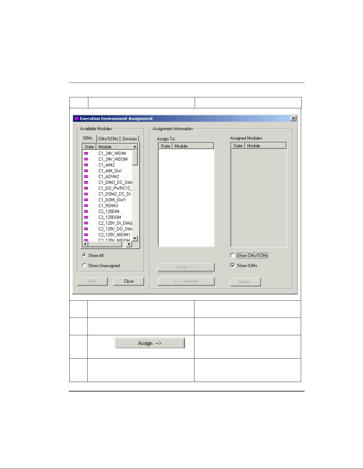
Assign Control Modules and IOMs to a CEEC300 block
To assign Control Modules and IOMs to a CEE
Step Action Result
6
Click listed IOM to be assigned.
7
Accept default CEE selection or click
desired CEE in list.
8
Click the
assign button.
9
Repeat Steps 2 to 4 to assign other
CMs/SCMs. Or, repeat Steps 5 to 8 to
assign other IOMs.
R301.1 Experion C300 Controller User's Guide 65
11/06 Honeywell
Highlights selection and applicable CEEs
appear in Assign To list.
Be sure correct CEE is selected in list.
Selected IOM is assigned to the selected
CEE and appears in the Assigned
Modules list.
Complete CM, SCM, and IOM
assignments.
Page 82

Copy Control Modules
To copy an existing Control Module
Step Action Result
10
Click the Close button.
Copy Control Modules
Prerequisites
• Control Builder is running
• Tree windows are open
Considerations
Closes dialog box and assigned
components now appear in CEE folder in
Project tab.
All illustrations used in the procedure are for example purposes only.
To copy an existing Control Module
Step Action Result
1
From the Project Tree, select the
desired Control Module block to be
copied.
2
Click Edit -> Copy.
Alternate method:
Click <Ctrl>-C.
66 Experion C300 Controller User's Guide R301.1
Honeywell 11/06
Selected Control Module block is
highlighted on the Project Tree.
Selected Control Module block is
saved to Control Builder clipboard
and Name New Function Block(s)…
dialog appears.
Page 83

Copy Control Modules
To copy an existing Control Module
Step Action Result
3
Change the Control Module block’s
Tagname in the Destination column of
the Name New Function Block(s) dialog
to a desired name or accept the default
name.
4
Click Next to proceed to the next dialog
page (if appropriate) and enter new
names as prompted to resolve any
existing connections and/or
associations.
5
Click Finish
The copied Control Module block is
assigned a new name.
Note: You may opt to keep the
default name which is simply the
original name with a number
appended to it.
If the CM contains connections to
outside blocks, an additional dialog
page appears which is used to
resolve any existing connections
and/or associations.
Copied Control Module block with
newly-designated name is pasted
onto the Project Tree.
R301.1 Experion C300 Controller User's Guide 67
11/06 Honeywell
Page 84

Assign I/O Modules to C300 IOLINK blocks
To assign Series C IO Modules and Process Manager IOMs to IOLINK blocks
Assign I/O Modules to C300 IOLINK blocks
In the C300 Controller environment, only Series C IO modules and Process Manager
IOMs can be assigned to IOLINK blocks.
ATTENTION
I/O assigned to the I/O Link of a C300 may only be associated with and
directly controlled by the CEE executing on the same C300 Controller. In
other words, I/O devices operating on a C300 Controller’s I/O Link may not
be directly associated with control strategies running on the CEE of another
controller.
Users should be aware and must calculate the I/O Link bandwidth consumed
by the planned I/O configuration for a given I/O Link. Use the I/O Link Unit
spreadsheet to calculate IOM loading for I/O Links. See also Priority IOMs
for more information
Prerequisites
• Control Builder is running
• Tree windows are open
Considerations
All illustrations used in the procedure are for example purposes only.
ATTENTION
You must assign Input/Output Processor Modules (IOM) to an IOLINK
before you can assign Input/Output Channels (IOC) to a given IOM.
TIP
Configure the IOM first to avoid duplicate IOM number error message when
attempting to assign an IOM to an IOLINK. The system checks for unique
IOM identification before assigning it to the IOLINK.
To assign Series C IO Modules and Process Manager IOMs to IOLINK blocks
Step Action Result
1
Click Edit->Execution Environment
68 Experion C300 Controller User's Guide R301.1
Honeywell 11/06
Calls up Execution Environment
Assignment dialog box. (There is no set
Page 85

Assign I/O Modules to C300 IOLINK blocks
To assign Series C IO Modules and Process Manager IOMs to IOLINK blocks
Step Action Result
Assignment. Or, click assignment
button in the toolbar.
default state for the dialog, so it may
come up with different active fields than
shown below.)
R301.1 Experion C300 Controller User's Guide 69
11/06 Honeywell
Page 86

Assign I/O Modules to C300 IOLINK blocks
To assign Series C IO Modules and Process Manager IOMs to IOLINK blocks
Step Action Result
TIP
You can use common <Shift> plus click and <Control> plus click actions to select
multiple items in Available Modules and Assigned Modules lists.
2
With IOMs tab selected, click desired
IOM to be assigned to given IOLINK.
70 Experion C300 Controller User's Guide R301.1
Honeywell 11/06
Highlights selection and configured
IOLINKs appear in the Assign To list.
Page 87

Assign I/O Modules to C300 IOLINK blocks
To assign Series C IO Modules and Process Manager IOMs to IOLINK blocks
Step Action Result
3
Accept default IOLINK selection or click
desired IOLINK in list.
4
Click the
assign button.
R301.1 Experion C300 Controller User's Guide 71
11/06 Honeywell
Be sure correct IOLINK is selected in list.
Selected IOM is assigned to the selected
IOLINK and appears in the Assigned
Modules list.
Note: You may need to select the
IOLINK in the list to view the IOM just
assigned to it.
Page 88
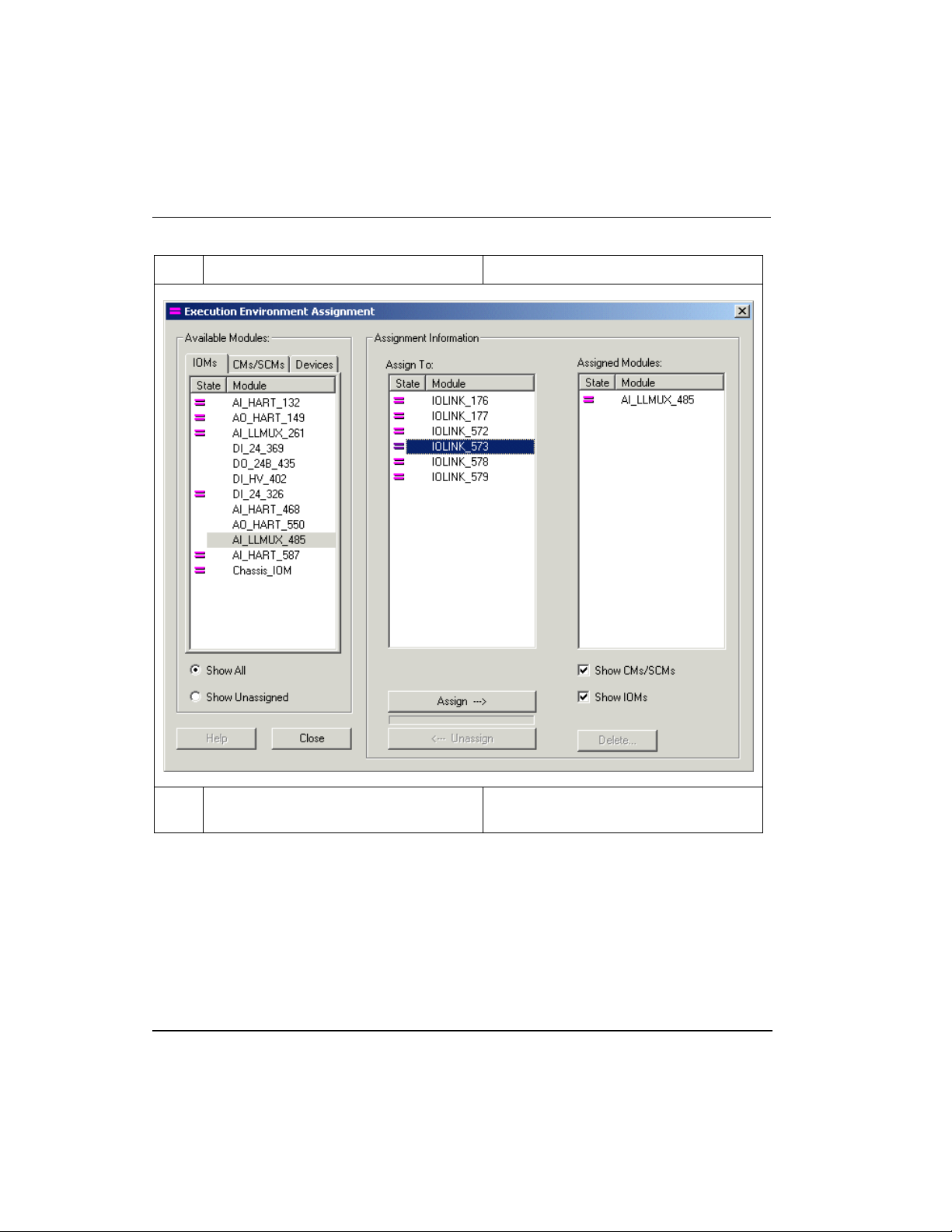
Assign I/O Modules to C300 IOLINK blocks
To assign Series C IO Modules and Process Manager IOMs to IOLINK blocks
Step Action Result
5
Repeat Steps 2 to 4 to assign other
IOMs.
72 Experion C300 Controller User's Guide R301.1
Honeywell 11/06
Complete IOM assignments.
Page 89

Add an I/O Channel to a Control Module
To assign Series C IO Modules and Process Manager IOMs to IOLINK blocks
Step Action Result
6
Click the Close button.
Closes dialog box and assigned
components now appear in IOLINK folder
in Project tab.
Add an I/O Channel to a Control Module
An IO Channel block represents a channel in one of the various IO modules (IOMs). The
IO Channel blocks can be added to a control module in the Project tab to build a process
control strategy.
The procedure is a drag and drop operation and is the same for any type IO Channel,
whether it is an AI channel in a Series C IO module or an DO channel in a Series A IO
module.
Prerequisites
• Control Builder is running
• Tree windows are open
Considerations
All illustrations used in the procedure are for example purposes only.
Blocks appear as Block Symbols on the Control Module chart.
R301.1 Experion C300 Controller User's Guide 73
11/06 Honeywell
Page 90

Add an I/O Channel to a Control Module
To add IO Channel blocks to a Control Module chart
To add IO Channel blocks to a Control Module chart
Step Action Result
1
Make sure a Control Module (CM) chart
is open.
Double-click the CM in the Project Tree
to open your CM chart so function blocks
may be added.
See Creating and Saving a Control
Module.
2
From the appropriate Library Tree group,
drag and drop the desired block (or
blocks) to the Control Module Control
Drawing (such as an AICHANNEL block
from the IOCHANNEL group).
The Control Module (CM) chart is open
so that function blocks may be added.
Desired block is shown in reverse video
on the tree.
The new function block appears on the
Control Module chart.
TIP
You can drag and drop Series C or PMIO Input/Output Channel (IOC) blocks directly
from IO Ms added to the Project tab to the Control Module.
You can not add IOC blocks to Control Modules already assigned to a Fieldbus
Interface Module (FIM).
3
Repeat Step 2 as many times as necessary to create the desired blocks for your
control strategy.
4
Create your control strategy by connecting the function blocks using the Insert wire
option.
REFERENCE - INTERNAL
For details to connect function blocks, see Connecting and disconnecting
blocks in the Control Building Guide.
If you are building a control strategy to include insertion points, refer to
Creating a strategy to use insertion points in the Control Building Guide.
74 Experion C300 Controller User's Guide R301.1
Honeywell 11/06
Page 91

Add an I/O Channel to a Control Module
To add IO Channel blocks to a Control Module chart
Figure 4 Control Module chart with an AICHANNEL block
R301.1 Experion C300 Controller User's Guide 75
11/06 Honeywell
Page 92

Add an I/O Channel to a Control Module
To add IO Channel blocks to a Control Module chart
76 Experion C300 Controller User's Guide R301.1
Honeywell 11/06
Page 93

C300 Configuration Form Reference
This section provides a summary all of the user visible parameters for a C300 Controller
and its associated blocks, (Secondary C300, CEEC300, and IOLINK blocks). The
parameters are grouped according to the tab where they reside in the configuration form.
For more details on these parameters see the Control Builder Parameter Reference.
Click on the topic in the table to view the parameters listed in that block’s configuration
form.
C300 Controller block
Secondary C300 block
CEEC300 function block
IOLINK block
C300 Controller Block
Main tab
Topic
The Main Tab is used to configure (and display configuration of) the C300 Controller.
See To configure a C300 Controller block
for the steps to configure a C300 Controller
block. The Main tab contains most of the parameters that must be configured when
setting up a C300 Controller. It also displays the important states of the C300 Controller
and supports the key commands associated with C300 Controller operation. Location and
Redundancy configuration can be done only in the Project Tree. The following table
summarizes the parameter data you can monitor and/or configure on the Main tab of the
configuration form for the selected C300 block.
Plain Text Parameter Name
Tag Name
R301.1 Experion C300 Controller User's Guide 77
11/06 Honeywell
Tag Name
User
Configurable
Project Only
System assigned or user
configured unique name.
Consisting of up to 16
characters and at least
one character must be a
letter (A-Z).
Notes
Page 94

C300 Controller Block
Main tab
Plain Text Parameter Name
Item Name
Application Image
Item Name
IMAGEVER
Version
Controller Command
C300COMMAND
Network Address Configuration
Device Index
Ethernet IP Address
DEVICEIDX
IPADDRESS
State Information
User
Configurable
Project Only
No
Monitoring
Only
Project Only
– Matches
Hardware
Setting
No
Notes
A non-unique name by
which an entity is known
within the context of the
enterprise model.
Identifies current version
of application firmware
installed in module.
Allows user to initiate
commands to a C300
Controller.
Unique FTE Device Index
of the C300 Controller.
Set on the C300 IOTA
switches.
IP address of the C300
Controller, derived as the
Embedded FTE Base
Ethernet IP Address plus
configured Device Index.
Controller State
C300STATE
No
Shows C300 Controller’s
current module state.
Redundancy Role
RDNROLESTATE
No
Shows C300 Controller’s
current redundancy role.
Synchronization
State
RDNSYNCSTATE
No
Shows C300 Controller’s
current synchronization
state.
Battery State
BATTERYNOTOK
No
Shows if battery voltage is
within ‘good’ range.
Soft Failures Present
(See Soft Failures
SOFTFAIL
No
Indicates if Soft Failures
are currently active.
Tab for details)
Redundancy Configuration
78 Experion C300 Controller User's Guide R301.1
Honeywell 11/06
Page 95

C300 Controller Block
Redundancy tab
Plain Text Parameter Name
Module is redundant
Secondary Tag
Name
Advanced Configuration
Alarming Enabled
GPS Time Source
Enabled
Temperature High
Alarm (deg. C)
CPU Free Low Alarm
(%)
MODISREDUN
SECMODNAME
ALMENBSTATE
GPSENABLE
(Currently not used)
OVERTEMPTHLD
CPULOLM
User
Configurable
Project only
Project only
Yes
Yes
Yes
Yes
Notes
Controller is part of
redundant pair
System assigned name
based on tag name with
sec suffix for secondary
block.
Allows user to set the
alarm reporting function
used when an alarm
condition is detected by
the function block.
Allows you to select GPS
as TIMESOURCE for time
synchronization.
Set threshold value for
module’s temperature high
alarm.
Allows user to set CPU
Free Low Capacity alarm
limit in percent.
CPU Free Low Low
Alarm (%)
CPULOLOLM
No
Fixed CPU Free Low Low
Capacity alarm limit in
percent
Redundancy tab
The Redundancy Tab displays redundancy-related information and allows redundancy
commands to be issued when the C300 FB is opened on the Monitor Tree in Control
Builder. The following table summarizes the parameter data you can monitor and/or
configure on the Redundancy tab of the configuration form for the selected C300 block.
See Redundancy parameters
also for further descriptions of these parameters.
Note that the Redundancy tab is exposed only when the Controller is configured as
redundant. The Module is redundant check box (MODISREDUN parameter) is checked
on the Main tab
of the C300 block.
R301.1 Experion C300 Controller User's Guide 79
11/06 Honeywell
Page 96

C300 Controller Block
Redundancy tab
Plain Text Parameter Name
Disable
DSBLSYNCCMD
Synchronization
Become Primary
Enable
BECMPRICMD
ENBLSYNCCMD
Synchronization
Initiate Switchover
SWITCHCMD
User
Configurable
Monitoring
only
Monitoring
only
Monitoring
only
Monitoring
only
Notes
Triggers a synchronizing/
synchronized/standby
redundant controller pair
to abort synchronization.
Triggers an
unsynchronized secondary
controller to transition into
the primary role in the
absence of a partner
controller.
Triggers an
unsynchronized redundant
controller pair to attempt
initial-synchronization.
Triggers a redundancy
role change where the
original primary controller
reboots into the secondary
role and the Synchronized
or Standby secondary
controller assumes the
primary role to continue
control operations.
Redundancy Status
Auto Synchronization
State
RDNAUTOSYNC
No
Shows current auto
synchronization state. If
enabled, not synchronized
controllers will attempt to
synchronize automatically
when conditions permit.
Redundancy
Compatibility
Inhibit Sync Reason
RDNCMPT
RDNINHIBITSYNC
No
No
Shows redundant partner
compatibility.
Shows the reasons for
inhibiting initial-sync.
Initial Sync Progress
(%)
RDNSYNCPROG
No
Shows current
synchronization progress
in percent.
80 Experion C300 Controller User's Guide R301.1
Honeywell 11/06
Page 97

C300 Controller Block
Redundancy tab
Plain Text Parameter Name
Last Synchronization
SYNCTIMEBEG
Time
Last Lost of Sync
SYNCTIMEEND
Time
Redundancy
RDNCTLABILITY
Controllability
Device Index
RDNDEVICEIDX
Redundancy Statistics
Traffic Redundancy
RDNXFERAVG
(bytes/sec)
Max Redundancy
RDNXFERMAX
Traffic (bytes/sec)
User
Configurable
No
No
No
No
No
No
Notes
Shows system time when
initial synchronization was
completed.
Shows system time when
last synchronization was
lost.
Shows whether the current
controller is Better, Equal,
or Worse to be the primary
controller (as compared to
the partner controller).
Shows the Device Index of
the redundant secondary
controller.
Current amount of
redundancy data traffic
across the redundancy
private path, in bytes per
second.
Maximum amount of
redundancy data traffic
across the redundancy
private path throughput
since power up or last
statistics reset.
Redundancy Delay
(%)
RDNDELAYAVG
No
The average of
redundancy delay CPU in
percent.
Max Redundancy
Delay (%)
RDNDELAYMAX
No
Historical maximum
redundancy delay CPU
value observed since
power up or last statistics
reset.
R301.1 Experion C300 Controller User's Guide 81
11/06 Honeywell
Page 98

C300 Controller Block
System Time tab
Plain Text Parameter Name
Max Initial Sync Time
(sec)
Max Switchover Time
(mSec)
OPM Freeze Ctrl
Time (msec)
Redundancy History
Time
Event
Reason
Redundancy Link
Failed
OPM Status
RDNISTIMEMAX
RDNSOTIMEMAX
RDNOPMFRZTIME
RDNHISTTIME
RDNHISTSTATE
RDNHISTREASON
RDNLINKFAILED
RDNOPMSTATUS
System Time tab
User
Configurable
No
No
No
No Show time of related state.
No
No
No
No
Maximum initial
synchronization time, in
seconds.
Maximum switchover time,
in milliseconds.
Maximum control freeze
time during an On-Process
Migration session.
Lists the last 16
redundancy related
activities.
Indentifies reason for
redundant history state
Indicates if Redundancy
link communications are
interrupted.
Status parameter
indicating the notifications
generated by the primary
controller during an OnProcess Migration
session.
Notes
The System Time tab contains information about the C300 Controller’s time source and
synchronization with that time source. The “System Time” and “System Time
Synchronization Status” subgroups on this tab provide current controller system time and
indicate the time source with which it is synchronized and status of synchronization with
that source. “SNTP Status” and “GPS Status” subgroups provide meaningful statistics
related to time synchronization with SNTP servers and GPS sources, along with their
status. The following table summarizes the parameter data you can monitor on the
System Time tab of the configuration form for the selected C300 block.
82 Experion C300 Controller User's Guide R301.1
Honeywell 11/06
Page 99

C300 Controller Block
System Time tab
Plain Text Parameter Name
System Time
Current System Time
Current System Time
CURTIME
TIMESOURCE
Source
System Time Synchronization Status
Time Synchronization
TIMESYNCSTAT
Status
Time of Last Time
TIMELASTSYNC
Sync
Skew at Last Time
TIMELASTSKEW
Sync (msec)
SNTP Status
SNTP Server
SNTPADDRESS
Address
SNTP Status
SNTPSTAT
User
Notes
Configurable
No
Shows current system
time.
No
Shows source of system
time. Default is Simple
Network Time Protocol
(SNTP).
No Shows time sync status.
No
Shows time controller time
synced with time source
No
Shows time skew from last
synced time.
No
Shows FTE address of
SNTP server.
No
Shows status for SNTP
time source.
SNTP Skew Limit
(msec)
SNTPSKEWTHLD
No
Shows the limit set for the
skew between the
controller time and the
SNTP time source
SNTP Skew Limit
Exceeded
NUMSNTPSKEWEX
No
Shows number times
SNTP skew threshold was
exceeded.
Max. SNTP Skew
(msec)
MAXSNTPSKEW
No
Shows maximum SNTP
skew recorded.
GPS Status
GPS Status
GPSSTAT
No
Shows status for time
source.
R301.1 Experion C300 Controller User's Guide 83
11/06 Honeywell
Page 100

C300 Controller Block
Statistics tab
Plain Text Parameter Name
GPS Skew Limit
(msec)
GPS Skew Limit
Exceeded
Max. GPS Skew
(msec)
GPSSKEWTHLD
NUMGPSSKEWEX
MAXGPSSKEW
Statistics tab
The Statistics Tab contains various statistical parameters used for maintaining and
monitoring C300 Controller performance. Such information includes CPU utilization,
hardware temperature and communications sub-system (CDA) statistics. The following
table summarizes the parameter data you can monitor on the Statistics tab of the
configuration form for the selected C300 block.
Plain Text Parameter Name
Reset All Statistics
STATSRESET
User
Configurable
No
No
No
User
Configurable
No
Notes
Shows GPS skew
threshold limit.
Shows number times GPS
skew threshold was
exceeded.
Shows maximum skew
recorded.
Notes
Button to initiate reset of
statistics in Monitoring
mode.
CPU Utilization
CPU Free (%)
Minimum CPU Free
(%)
Hardware Temperature
Current Temperature
(deg. C)
84 Experion C300 Controller User's Guide R301.1
Honeywell 11/06
CPUFREEAVG
CPUFREEMIN
CTEMP
No
No
No
Current CPU Free value,
in percent.
Minimum CPU Free value,
in percent. Value
represents minimum
recorded since module
power up or last statistics
reset.
Current operating
temperature, in degrees C.
 Loading...