

Page 1
Doc. No.: EP03-390-501
Revision
Description
Date
Included information about support for 30 ELCN ES-Ts per ESVT cluster in
section “Experion LCN System Requirements”.
Experion Local Control Network
Technical Specification
Version: D
Date: March 2020
Revision History
A Initial version. August 2017
B Addition of ELCN EPLCG, EHB, and redundant AM. September 2018
C Addition of ELCN NG. October 2019
D
March 2020
Page 2

Experion Local Control Network Specification
Table of Contents
1 Product Introduction............................................................................................................................................................................................................................ 5
1.1 Experion Local Control Network System Overview....................................................................................................................................................... 5
1.2 Universal Embedded Appliance (UEA) Overview .......................................................................................................................................................... 6
1.2.1 Experion LCN Bridge .......................................................................................................................................................................................................... 6
1.2.2 Experion LCN Appliance Nodes .................................................................................................................................................................................... 7
2 Experion LCN Architecture .............................................................................................................................................................................................................. 8
2.1 Experion LCN System Architecture Overview ................................................................................................................................................................. 8
2.2 Experion LCN Hardware Overview....................................................................................................................................................................................... 9
2.2.1 Universal Embedded Appliance Installation.......................................................................................................................................................... 9
2.2.2 Universal Embedded Appliance Processor Module........................................................................................................................................11
2.2.3 Universal Embedded Appliance Front Panel ......................................................................................................................................................12
2.2.4 Universal Embedded Appliance Termination Assembly ...............................................................................................................................13
3 Experion LCN Requirements ........................................................................................................................................................................................................16
3.1 Experion LCN System Requirements ................................................................................................................................................................................16
3.2 System Software Requirements ..........................................................................................................................................................................................17
4 Experion LCN Functional Overview ...........................................................................................................................................................................................19
4.1 General Overview .......................................................................................................................................................................................................................19
5 Experion LCN Specifications ........................................................................................................................................................................................................20
6 Models and Parts ...............................................................................................................................................................................................................................23
6.1 Experion LCN Model Numbers .............................................................................................................................................................................................23
6.2 Experion LCN Upgrade Kits ...................................................................................................................................................................................................24
6.3 Experion LCN Replacement Parts ......................................................................................................................................................................................25
7 Regulatory Compliance ...................................................................................................................................................................................................................26
7.1 Regulatory Compliance Statements ....................................................................................................................................................................................26
Disclaimer ....................................................................................................................................................................................................................................................27
PAGE | 2
Page 3

Experion Local Control Network Specification
Table of Figures
Figure 1 Example of Experion LCN System Architecture Overview .......................................................................................................................... 8
Figure 2 Dual UEA Installation Front View ................................................................................................................................................................................ 9
Figure 3 Dual ELCN UEA Installation in Rack ......................................................................................................................................................................10
Figure 4 Dual ELCN UEA Installation Cabling for ELCN Bridge and ENIM/AM/EHB .................................................................................10
Figure 5 Dual ELCN UEA Installation Cabling for ELCN EPLCG ...............................................................................................................................11
Figure 6 Processor Module (with front panel).......................................................................................................................................................................12
Figure 7 Front Panel .............................................................................................................................................................................................................................12
Figure 8 ELCN Bridge, ENIM, AM, EHB and NG Termin ation Assembly ...............................................................................................................13
Figure 9 ELCN Bridge, ENIM, AM and EHB Termination Assembly Detail ...........................................................................................................14
Figure 10 Bridge, ENIM, AM, EHB, NG Termination Assembly Ethernet Port LED Indicators ..................................................................14
Figure 11 EPLCG Termination Assembly Rear Ports ......................................................................................................................................................15
Figure 12 EPLCG Termination Assembly Ethernet Port LED Indicators ...............................................................................................................15
Table of Tables
Table 1 Acronyms and Definitions ................................................................................................................................................................................................ 4
Table 2 Summary of the Experion LCN Nodes and Platforms ....................................................................................................................................... 6
Table 3 Bridge, ENIM, AM, EHB and NG Termination Assembly Ethernet Port LED Definition ...............................................................14
Table 4 EPLCG Termination Assembly Ethernet Port LED Definition ....................................................................................................................15
Table 5 Summary of LCN/ELCN limits (assuming no FTEBs with C200, C200E or FIM2). ..........................................................................16
Table 6 System Software ...................................................................................................................................................................................................................17
Table 7 General Experion LCN Specifications ......................................................................................................................................................................20
Table 8 General ELCN Bridge/Appliance Specifications ................................................................................................................................................20
Table 9 MAU Power (from UEA) ....................................................................................................................................................................................................20
Table 10 ELCN Bridge/Appliance Environmental Requirements ...............................................................................................................................21
Table 11 ELCN Bridge/Appliance Front Panel General Specifications ..................................................................................................................21
Table 12 ELCN Bridge/ENIM/AM/EHB/NG Termination Assembly General Specifications ........................................................................22
Table 14 UEA Mount (19” Rack) General Specifications ................................................................................................................................................22
Table 15 Weights and Dimensions ..............................................................................................................................................................................................22
Table 16 Experion LCN Model Numbers ..................................................................................................................................................................................23
Table 17 Upgrade Kit Models Available To Perform Upgrades To ELCN ..............................................................................................................24
Table 18 Optimum Replacement Parts ......................................................................................................................................................................................25
PAGE | 3
Page 4

Experion Local Control Network Specification
Term
Definition
Acronyms and Definitions
Table 1 Acronyms and Definitions
ACE-T Application Control Environment - TotalPlant™ So lution
AM Application Module
CF9 Control Firewall (9 ports including the Uplink port)
E-APP Experion Application Processing Platform
EHB Experion Hiway Bridge
ELCN Experion Local Control Network
ENIM Enhanced Network Interface Module
EPLCG Enhanced Programmable Logic Controller Gateway
ES-CE Experion Station – Console Extension
ES-F Experion Station – Flex
ES-T Experion Station - TotalPla nt™ Sol uti on
ESVT Experion Server TotalPlant™ Solution
EUCN Enhanced Universal Control Network
FIM Fieldbus Interface Module
FTE Fault Tolerant Ethernet
FTEB Fault Tolerant Ethernet Bridge
GUS Global Universal Station
HM History Module
LCN Local Control Network
LCNE Local Control Network Extender
MAU Media Access Unit
NG Network Gateway
O/S Operating System
PIN Plant Information Network
PHY Physical Layer
TPN TPS Process Network
TPS TotalPlant™ Solution
UCN Universal Control Network
US Universal Station
UxS Universal StationX
PAGE | 4
Page 5

Experion Local Control Network Specification
1 Product Introduction
Experion LCN further continues innovation for Honeywell customers. Using the proven Experion Fault Tolerant
Ethernet (FTE) infrastructure, a new Experion Local Control Network (ELCN) Bridge connects Experion to Classic
COAX LCN. Once this connection is established, Classic LCN COAX-based nodes can be replaced with FTE-based
Experion LCN nodes, al low ing the removal of these LCN nodes as they are migrated one at a time.
With Experion LCN, existing control strategy, field terminations, applications, history and graphics can be retained,
allowing users to focus on high value improvements. It minimizes operating disruptions, maintains overall consistency
and delivers optional lifecycle advantages with virtualization.
1.1 Experion Local Control Network System Overview
The Experion LCN is the Fault Tolerant Ethernet (FTE) version of the classic coaxial cable-bas ed LCN. T he obj ect ive
of the ELCN is to convert Classic LCN COAX-based nodes to FTE-based Experion LCN nodes. This conversion can
occur incrementally, over time, without shutting down LCN nodes. Ultimately, all LCN nodes may be migrated to
ELCN, allowing for a complete elimination of the LCN-based system.
ELCN is divided into two general parts. The first part is the ELCN Bridge product which has a singular purpose or
operating as a bridge between the LCN and FTE. The second part is the conversion of LCN nodes to Experion LCN
nodes. An Experion LCN node is a hardware/software entity that performs the same function as its LCN equivalent
node where an FTE network replaces the COAX network.
Migration to the ELCN requires an ELCN Bridge node to connect the Classic LCN to the Experion LCN, creating a
single logical hybrid network. The ELCN Bridge must be installed as a redundant pair.
The ELCN Bridge translates LCN messages into Ethernet messages and vice versa. The ELCN Bridge provides a
means for legacy LCN functions and the Experion version of those functions to co-exist and inter-operate during
migration of the classic LCN nodes to Ex peri on LCN n odes . Once an LCN Br id ge cr eates a communication path
between the LCN and the FTE, classic LCN nodes can be upgraded one at a time. During the upgrade process the
node number, such that the node's logical role in the system remains unchanged. The legacy node that migrates from
a physical LCN segm ent to the ELCN net w ork appear s uncha nge d in conf ig urati o n to its oper ating peer nod e s .
Upgrade process may occur over an extended period of time until no nodes remain connected to LCN, other than the
ELCN Bridge. At this time the ELCN Bridge may be removed (as the final step of the upgrade) and reused as a spare
part (Experion LCN node or bridge).
Before migration to ELCN can be accomplished, an Experion system with an ESVT, Microsoft 10 O/S and Server
2016, are required. The following is a summary of the Experion LCN nodes and their platforms:
PAGE | 5
Page 6
Experion Local Control Network Specification
Physical
Virtual
Available in
TPN R687
Available in
R688.1
Available in
Virtual Machine/x86
Premium)
ELCN Bridge
X
X X X
ELCN TPS Node s:
ESVT
Windows Server 2016
Windows Server 2016
X X X
ES-T
Windows 10 or
Windows Server 2016
Windows Server 2016
X X X
ACE-T
Windows Server 2016
Windows Server 2016
X X X
E-APP
Windows Server 2016
Windows Server 2016
X X X
HM
Windows Server 2016
Windows Server 2016
X X X
ELCN Appliance and Virtual Nodes:
ENIM X
Linux X X
X
Non-redundant AM
X Linux X X
X
EPLCG**
X Linux** X
X
Redundant EPLCG
X Linux**
X
EHB X
Linux X
X
Redundant AM
X Linux X
X
NG X
Linux
X
Table 2 Summary of the Experion LCN Nodes and Platforms
COTS PC/x86
(Dell or HP)*
* For a list of supported DELL and HP hardware platforms, refer to the Experion PKS Software Installation Guide.
** Virtual EPLCG will not be available for a production application, but only for Open VEP (Virtual Engineering Platform). The virtual
EPLCG may be used for configuration or training purposes.
UEA
(Essentials or
Experion
R501.2 and
Experion
R501.4 / TPN
Experion
R501.6 / TPN
R688.3
1.2 Universal Embedded Appliance (UEA) Overview
The Universal Embedded Appliance is a hardware component of ELCN. The UEA can be configured to be a bridge
between LCN and ELCN, and also configured to be an ELCN appliance (node), which allows for LCN nodes to be
replaced by their ELCN equivalent nodes.
1.2.1 Experion LCN Bridge
The ELCN Bridge is a new node that enables upgrade of classic LCN nodes to Experion LCN nodes and allows for
Experion LCN nodes to coexist with a classic LCN network. The UEA is used to function as an ELCN bridge. The LCN
connection to an ELCN bridge is made via Media Access Unit (MAU) cables. The MAU cables contain electronics that
convert LCN analog signals to digital signals, which are then processed by the ELCN Bridge to be made compatible
with ELCN FTE. The reverse occurs when ELCN FTE signals are sent to LCN nodes. This two-way process allows for
full two-way LCN-ELCN communication.
The ELCN Bridge is not seen on the LCN system status, but on Experion. The ELCN Bridge is monitored and
operated from Experion.
ELCN Bridge Requirements:
The following requirements must be in place prior to implementing an ELCN Bridge for LCN to Experion LCN node
migration:
• TPN/LCN Release R688.1 or later.
• Experion PKS for ELCN Bridge is Experion Release R501.4 or later.
• Experion TPS Nodes (ES-T, ESVT, E-APP, ACE-T) must be running Windows 10or Sever 2016 Operating
• The redundant pair of ESVTs must be running Windows Server 2016
• The Experion Base IP address must be configured
• The BOOTP Server service must be running on ESVT
• NCF clock must be configured on ESVT server
System
PAGE | 6
Page 7

Experion Local Control Network Specification
ELCN Bridge Configuration:
Configuration of the ELCN Bridge requires the following Experion applications:
• Firmware Manager Tool (to load ELCN Bridge or Appliance firmware)
• Control Builder (to configure ELCN Bridge or Appliance)
1.2.2 Experion LCN Appliance Nodes
An ELCN Appliance node is a UEA-based TPN personality that communicates through its legacy LCN interface (which
now communicates over FTE). An Experion LCN node has the same personality image as its LCN equivalent – no
modifications are needed to load the personality. ECLN nodes can be pure virtual machines, hardware-based (UEA),
or a mixture of both.
When all LCN nodes are converted to ELCN, the ELCN Bridge (UEA) can be decommissioned and used as a spare
part (an ELCN appliance, or bridge).
Experion Release 501 introduces the ELCN Bridge and functionality for Experion TPS nodes which only needs an
FTE connection (no LCNP4 card, MAU connection, or COAX cabling).
PAGE | 7
Page 8
Experion Local Control Network Specification
2 Experion LCN Architecture
2.1 Experion LCN System Architecture Overview
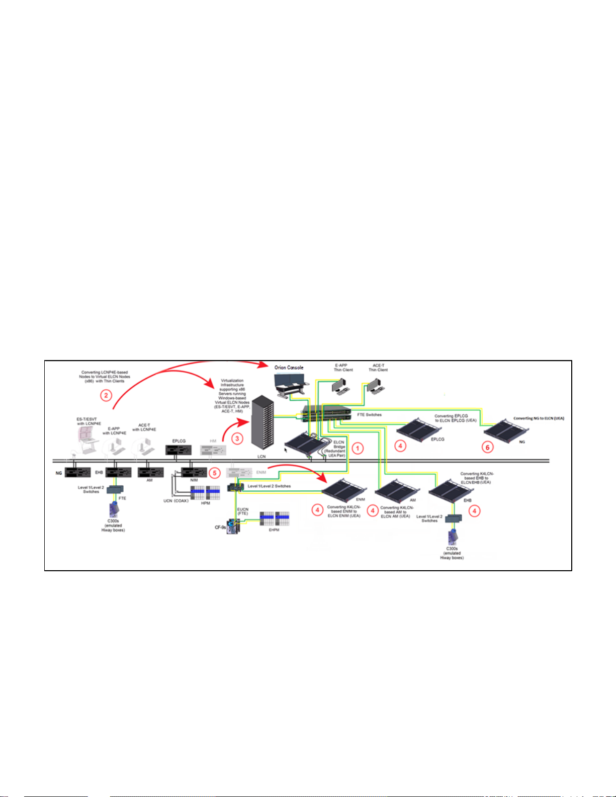
The diagram that follows is an example of a basic ELCN system that includes the following migration scenario:
1. A redundant pair of ELCN Bridge UEA boxes has been installed and connected to the LCN and FTE
networks.
2. The Microsoft Windows based nodes (E SVT , E S-T, ACE-T, and E-APP) have been converted from
LCNP4E-based nodes to run as Virtual Machines on x86 servers running Microsoft Windows operating
system. These Virtual Machines have been provided with thin clients. The diagram shows a Honeywell
Orion Console used for the control room thin clients.
3. The History Module has been virtualized to run as a Virtual Machine on an x86 server platform. The History
Module can be Physical on x86 server platform with Server 2016.
4. The K4LCN-based ENIM has been converted to UEA hardware. Note that the LCN NIM, AM, EPLCG, NG
and EHB with C300s can also be migrated to equivalent ELCN UEA nodes.
5. This example system requires the ELCN Bridge to get data from the remaining LCN NIM, AM, EPLCG, EHB
and NG for the Experion System.
6. The K4LCN-based NG has been converted to UEA hardware. Note the details of the NG Planning,
Installation, and Service are covered in the Experion Local Control Network Gateway Planning, Installation
and Service Guide (HWDOC-X608-en-A).
Figure 1 Example of Experion LCN System Architecture Overview
Some LCN nodes that provide Man Machine Interface (MMI) are US, GUS and UxS. These will be converted to ELCN
variants (ES-T, ACE-T and E-APP nodes). ACE-T and E-APP not used for graphics or MMI. only ES-T or Flex can be
used to replace US, GUS and UxS.
These Experion LCN nodes can be either virtual nodes in VMware or the personality will be contained in a stand-alone
PC (bare-metal node), but there will be no LCN connected (LCN P4 E2) har dw ar e.
Legacy LCN based user interface nodes (also called MMI nodes) such as the Universal Station (US), the UxS (third
party user interface), and the GUS, must be converted to forms of ES-T.
PAGE | 8
Page 9
Experion Local Control Network Specification
Classically, all Windows based user interface nodes on the LCN used LCNP electronics (LCNP, LCNP4, LCNP4M,
LCNP4E and LCNP4E2) to attach to the LCN COAX. As these nodes are converted from the LCN COAX to FTE, the
LCNP electronics must be removed. Two options are available:
• The user interface node (ES-T, ESVT, E-APP or ACE-T) PC-based (Experion) software must be upgraded
to use both encapsulated LCN communication and the legacy LCN communication. This can be done if the
hardware platform of the bare-metal PC is still supported by the OS platform of Windows 10 (for ES-T) and
Server 2016 (for ACE-T, E-APP and ESVT). The upgraded user interface node may be used in the same
manner as before.
• Virtualize the user interface node and remove the old PC platform. This requires the use of a thin client and
peripherals (video, keyboard, cursor control, removable media, etc.) to provide user interface functions.
• ELCN Bridge (must be installed as a redundant pair)
• ACE-T (Application Control Environment - TPN connected, Physical and Virtual)
• ES-T (Experion Station - TPN connected, physical and virtual platforms)
• ESVT (Experion Server for TPS, physical and virtual platforms)
• E-APP (Experion APP node, physical and virtual platforms)
• HM (physical and virtual platforms)
• ENIM (UEA-based and virtual platforms)
• AM (UEA-based and virtual platforms)
• EPLCG (UEA-based and virtual platforms)
Note: Virtual EPLCG is not supported for production environment
• EHB (UEA-based and virtual platforms)
• NG (UEA-based and virtual platforms)
2.2 Experion LCN Hardware Overview
The Universal Embedded Appliance (UEA) is the hardware platform used for the ELCN Bridge and ELCN Appliance
nodes. It is a multipurpose platform, havi ng a 1U high r ac k -mount enclosure. It has two major subassemblies that
mate together; a processor module (front box) and a termination assembly (rear box). These subassemblies mate
together and reside in a 19-inch 1U rack mounting shelf. The shelf can house two side-by-side UEAs. Two UEAs can
be installed in a redundant configuration using redundancy cables that interconnect the primary and backup UEA
boxes.
2.2.1 Universal Embedded Appliance Installation
UEAs are rack-mounted in Honeywell LCN cabinets or 19-inch rack mount server cabinets. Front and rear cabinet
access is required to accomplish cabinet mounting and module cabling. The UEA processor modules are removable
from the front of the rack by loosening two captivated retaining screws located behind “flip-up” latches. The
termination assembly may remain installed during the processor module removal or installation.
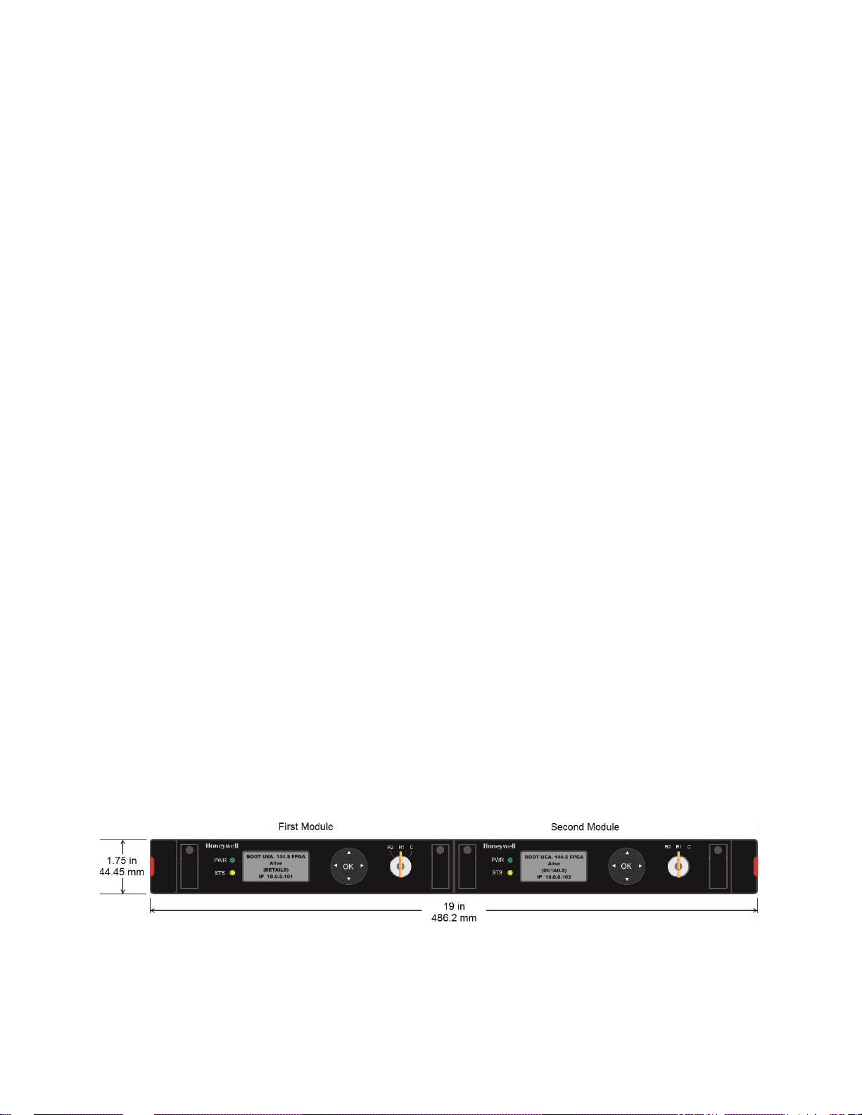
ELCN redundant module dimensions are shown below:
Figure 2 Dual UEA Installation Front View
PAGE | 9
Page 10

Experion Local Control Network Specification
Figure 3 Dual ELCN UEA Installation in Rack
The following diagram illustrates the installed UEA cable connections for the ELCN Bridge and ENIM/AM/EHB/NG
Appliances:
Figure 4 Dual ELCN UEA Installation Ca bling for ELCN Bridge and ENIM/AM/EHB/NG
Only the ELCN Bridge UEA uses the MAU cables to connect to the LCN coax cables. Non-bridge UEAs (Appliances)
only interface directly with other FTE nodes. The MAU electronics convert LCN analog signals to digital signals, which
are then processed by the ELCN Bridge to be made compatible with ELCN FTE. The reverse occurs when ELCN FTE
signals are sent to LCN nodes. This two-way process allows for full two-way LCN-ELCN communication.
The ELCN Bridge must be deployed as a redundant pair of UEAs. Redundant UEAs (the local UEA and the partner
UEA) have a redundancy port cable connected between them.
PAGE | 10
Page 11

Experion Local Control Network Specification
The following diagram illustr ates an examp le of installed UEA cable connections for the ELCN EPLCG:
Figure 5 Dual ELCN UEA Installation Ca bling for ELCN EPLCG
Note: The EPLCG cabling will differ according to various customer system configurations.
2.2.2 Universal Embedded Appliance Processor Module
The processor module is a core component of the UEA. It has a processor, user interface display, push button
controls, power supply and fan. This module contains no user serviceable parts and must be replaced as a unit. The
processor ships with a base image that supports test capability and loading of an image that provides application
functionality.
PAGE | 11
Page 12

Experion Local Control Network Specification
Figure 6 Processor Module (with front panel)
2.2.3 Universal Embedded Appliance Front Panel
The front panel provides power and status LEDs, and a 4-line, 20-character display. This display is used to show more
detailed status information and provide a means of configuring the running application. A five key navigation control is
used to manipulate cursor position and enter configuration information. A general purpose 3 position key switch
provides the ability to lockout front panel configuration entry and select run modes as defined by the installed
application. The key is removable in any position with the UEA powered or unpowered.
The key switch C position allows configuration of device and restart from the front panel. The R1 and R2 positions are
application runtime options. In the R1 or R2 positions, the navigation display will show the UEA IP address and current
application status.
The front panel is used to assign the UEA FTE Device Index, which is required for the module to be assigned an FTE
IP Address.
Figure 7 Front Panel
The front panel main components are:
• Power LED (illuminates when 3.3V display power is applied)
PAGE | 12
Page 13

Experion Local Control Network Specification
• Status LED, which may display 3 colors:
o Red: failure
o Amber: warning
o Green: normal operating state
o Blue: the node state is NotConfig or NotLoaded
• LCD display (4 lines, 20 characters per line)
• 5-button navigation control, which provides the user interface for:
o Choosing items on the display screen (for example, highlighting/selecting)
o Modifying items (as applicable) on the display screen (for example, entering a new value for a
highlighted item)
o Navigation among display screens (for example, pressing OK to enter a different screen)
• 3-position key switch, which is used to select:
o C: Configure the UEA (node configuration mode, including options to reboot or restore to factory
image)
o R1: Runtime 1 (read-only control mode, no write access to the process)
o R2: Runtime 2 (read-write control mode, allows writes to the process)
• Captive screws for securing to the rack mount shelf assembly
2.2.4 Universal Embedded Appliance Termination Assembly
The termination assembly (rear box) provides all external cable connections to the processor assembly. This separate
assembly allows the processor box to be replaced while keeping all cables connected to the connector assembly. The
termination assembly contains no user serviceable parts and must be replaced if damaged.
The rear port connector usage is application dependent. Refer to application documentation for correct
assignment/usage of connectors.
2.2.4.1 ELCN Bridge, ENIM, AM, EHB and NG Termination Assembly
The connector ports include:
• 5 Ethernet connectors (2 sets of paired, 1 single)
• 2 Local Control Network (LCN) Media Access Unit (MAU) mini D connectors
Figure 8 ELCN Bridge, ENIM, AM, EHB and NG Termination Assembly
PAGE | 13
Page 14

Experion Local Control Network Specification
Color/State
On/Off/Blinking
Off for no connection; and blinking for activity
On/Off
ON for 100Base
Figure 9 ELCN Bridge, ENIM, AM, EHB and NG Termination Assembly Detail
Note: The 5 Ethernet ports are for downlink, FTE A and B, and redundancy connections.
Note: For Network Gateway ETH-1 is used for PIN Cable A and that (optionally) ETH-2 is used for PIN Cable
A.
The following figure and table describe the LED indicators of Ethernet ports:
Figure 10 Bridge, ENIM, AM, EHB and NG Termination Assembly Ethernet Port LED Indicators
Table 3 Bridge, ENIM, AM, EHB and NG Termination Assembly Ethernet Port LED Definition
Item No. Indication
LED
Description
1, 3, 5, 7, 9 Ethernet P ort Link/ Active
2, 4, 6, 8, 10 Ethernet Port Speed
2.2.4.2 ELCN EPLCG Termination Assembly
The connector ports include:
• 2 Ethernet connectors (FTE A and FTE B)
• 2 isolated RS-232 field ports used for serial communication with PLCs and communication interfaces (PORT 1
and PORT 2)
Green
Yellow
On for connection;
OFF for 10Base
PAGE | 14
Page 15

Experion Local Control Network Specification
Color/State
On/Off/Blinking
Off for no connection; and blinking for activity
On/Off
ON for 100Base-TX
• 1 a non-isolated RS-232 port used for protocol selection (CONFIG JUMPERS)
• 1 RS-422 port used for redundancy communication between ELCN EPLCGs, and Ethernet communication
signals (used for Experion redundancy) (INTER-LINK)
Figure 11 EPLCG Termination Assembly Rear Ports
The following figure and table describe the LED indicators of Ethernet ports:
Figure 12 EPLCG Termination Assembly Ethernet Port LED Indicators
Table 4 EPLCG Termination Assembly Ethernet Port LED Definition
Item No. Indication
2,4 Ethernet Port Link/ Active
1, 3 Ethernet Port Speed
LED
Green
Yellow
Description
On for connection;
OFF for 10Base-T;
PAGE | 15
Page 16

Experion Local Control Network Specification
LCN/ELCN Capacity Limits
Qty
Notes
3 Experion LCN Requirements
3.1 Experion LCN System Requirements
The following ELCN system requirements apply to the deployment of ELCN:
• All ELCN systems require at least one redundant Bridge pair prior to adding any ELCN Appliance node.
• A minimum ELCN system consists of a redundant ESVT pair. If LCN nodes are present, a minimum ELCN
system then must also have one redundant UEA ELCN Bridge pair.
• If two UEA modules are installed in the same/common/single UEA mounting rack, they can be any
combination of node types
• A maximum ELCN system is determined by the number of TPS nodes allowed on a given Local Control
Network (LCN). For a network without LCN extenders, 64 nodes (includes ELCN Bridges) are allowed. For
a network with LCN extenders, 96 nodes are allowed per system. Only one ELCN Bridge redundant pair is
permitted per LCN.
• A maximum of 40 LCN loads are permitted per LCN COAX segment. A Dual Node Module counts as one
LCN electrical node load towards the 40-node limit irrespective of whether one or two nodes are installed in
the DNCF.
• Only one FTE Community is permitted per ELCN. If multiple ESVTs within the LCN to be converted to
ELCN have been assigned to multiple communities, then those communities would need to collapse into
one FTE community before migrating to ELCN.
• If, having K2LCN cards can impact performance. Must upgrade all K2LCN boards with K4LCN board before
executing the ELCN migration.
Table 5 Summary of LCN/ELCN limits (assuming no FTEBs with C200, C200E or FIM2).
Maximum number of ELCN Bridge pairs per LCN/ELCN 1 Redundant pair
Maximum number of nodes per LCN/ELCN, without LCN
Extenders
Maximum number of nodes per LCN/ELCN, with LCN
Extenders
Maximum number of nodes per COAX LCN segment 40
Maximum number of ESVT server pairs (clusters) per LCN 5 Redundant pairs
Maximum number of ES-Ts per ESVT cluster* 20*
Maximum number of ES-Ts + ES-CE per ESVT cluster* 30*
Maximum number of ES-Ts + ES-CE + ES-F per ESVT cluster 40
Maximum number of AM personality instances (AM, ESVT,
ACE-T and E-APP) per LCN
The maximum number of ELCN NGs per LCN is limited to 2
(One Responsible and One Alternate
The maximum number of NGs on a PIN is 63
ELCN bridge does not contribute
64
to the total number of LCN nodes
ELCN bridge does not contribute
96
to the total number of LCN nodes
ELCN bridge does contribute to
the COAX segment total (+2)
-
There is no need for more than 2
NGs since one NG can access
data from all other nodes on a
PIN (the second NG is to act as a
“hot spare” or Alternate NG in
case the responsible NG fails)
The limit is set to limit the data
throughput on the new Ethernet
PIN.
PAGE | 16
Page 17

Experion Local Control Network Specification
Errors may occur when fiber optic
cable is broken, or when LCNEs
Minimum number of LCN nodes per integrated LCN/ELCN
system
* Maximum number of ELCN ES-Ts per ELCN ESVT cluster – Beginning with Experion R501.6 and TPN R688.3, you
can configure up to 30 ELCN ES-Ts per ELCN ESVT cluster without impacting the system performance, however,
ensure that the following conditions are met, if not, configuration of up to 20 ELCN ES-Ts is supported per ESVT
cluster:
• This enhancement is not supported if there are C300 controllers integrated with your system, this includes
products such as, Experion Hiway Bridge (EHB) and C300 controller based Enhanced Logic Manager Module
(ELMM).
• While using the increased number of ELCN ES-Ts, enough care must be taken to ensure that the data owners
and controllers in the LCN are not loaded beyond their documented limits.
• When you are migrating GUS or US stations to ES-Ts, you must consider the number of ES-Ts which already
exist in the network.
are powered off, if only two nodes
exist on a remote segment.
3
During LCNE failure, these nodes
form their own token ring. If one
node fails both nodes are lost.
o After migrating existing GUS or US stations to ES-Ts, do not create additional load on the data
owners by invoking displays such as, HMIWeb, GUS and US displays.
o If you are using HMIWeb display instead of US/GUS display after configuring up to 30 ES-Ts and this
causes additional load on the data owners, examine the station and display update rates, and check
that the default station update rate is not set at 1 second.
ATTENTION
If the ELCN System Management Dashboard feature is configured in Station and you are
trying to configure more than 20 ELCN ES-Ts, this results in high PARSEC load on the
ENIMs in the LCN and may lead to an undesirable behavior. The PARSEC value
approximately increases by 20 per ELCN ES-T configured under the network. Therefore, it
is important that you consider the existing load on an ENIM before you configure more
ELCN ES-Ts with the ELCN System Management Dashboard feature configured in the
network.
3.2 System Software Requirements
The table in this section identifies the system software that is required for proper operation of ELCN systems.
Table 6 System Software
System Software Minimum Software Release Level is R501.4
Honeywell Experion R501 or later (depending on functionality
needed).
Honeywell TPN/LCN
Windows 10 O/S for Experion Station TPS (can also run on
Windows Server 2016)
Windows Server 2016 for Experion Server TPS, Experion
APP, ACE-T, and History Module
PAGE | 17
R688.1 or later (depending on functionality
needed).
Initial
Initial
Page 18

Experion Local Control Network Specification
PAGE | 18
Page 19

Experion Local Control Network Specification
4 Experion LCN Functional Overview
4.1 General Overview
The ELCN is the Fault Tolerant Ethernet (FTE) version of the coaxial cable-based Classic LCN. ELCN architecture
runs an existing, unmodified LCN system on a new platform. An Experion LCN node uses an emulated LCN
personality and Ethernet encapsulated LCN communications. There is no coaxial cabling or LCNI device; instead, an
emulated LCNI device is presented to the personality. This allows for a range of new deployment options for K4LCNbased subsystems (AM, ENIM, HM, PCLG/EPLCG, EHB and NG) and LCNP4-based subsystems (ES-T, ESVT, ACET, E-APP). Deployments may be virtual or hardware platforms.
The Universal Embedded Appliance, when used as an ELCN Bridge, provides access from the ELCN FTE networking
environment to the legacy Classic LCN COAX networking environment during the migration process. ELC N Br id ge
redundancy enables either of the paired bridges to assume the role of primary device. A redundant bridge pair
occupies consecutive LCN node numbers. The ELCN Bridge also includes security controls provided by the UEA
platform on which it is based.
The ELCN Bridge supports the following features:
• Transfer of LCN protocol traffic between ELCN and
• Physical address filtering
• Rate limiting to prevent congestion
After establishing the ELCN Bridge, you can migrate each Classic LCN node to the new architecture, one at a time,
and then remove its LCN coaxial connection. All existing user-created LCN data objects (such as checkpoints, button
configuration files, display objects, and CL/AM objects) run on all ELCN platforms, without recompile, rebuild, or
reconstruction. For any given user-created data object source file, there will be only one compiled object file.
The LCN to ELCN migration process may need to occur over an extended period of time, but at the end of the
migration, no nodes remain connected to the Classic LCN network other than the ELCN Bridge. You remove the
ELCN Bridge as the final step of the upgrade and repurpose its hardware as spare parts.
COAX LCN network segments
PAGE | 19
Page 20

Experion Local Control Network Specification
Item
Specification
Item
Specification
5 Experion LCN Specifications
Table 7 General Experion LCN Specifications
Maximum length of copper cable 100 meters
Maximum length of fiber optic cable
Network type Fault Tolerant Ethernet
Data throughput speed 100 Mbit/sec (100 Base T)
Corrosive environment G4 (Severe)
Table 8 General ELCN Bridge/Appliance Specifications
2 kilometers
With the help of SFP port of switch this can be support 2
Kilometer. current UEA based FTE port not supported
fiber optic.
Table 9 MAU Power (from UEA)
Input Voltage 3.3V DC +/- 5%
Input Current Typical 50 mA, Maximum 70 mA
PAGE | 20
Page 21

Experion Local Control Network Specification
Item
Specification
LCD Type
FSTN/Tranflective/Positive
LCD View Area
52.0mm *23.4mm
LCD Character array
20 characters *4 rows
LCD Backlight
Write LED, adjustable
LCD View Direction
12O’clock
LED
2 LEDs
Power Indicator with Green
Status Indicator with the following colors:
Red
Amber
Green
Blue
Key Switch 1
3 positions (R2, R1, C)
Navigation (Keypad)
4 Direction key + 1 Enter Key
Note 1 Each Package has 2 keys
Table 10 ELCN Bridge/Appliance Environmental Requirements
Table 11 ELCN Bridge/Appliance Front Panel General Specification s
PAGE | 21
Page 22

Experion Local Control Network Specification
Item
Specification
Main purpose for the ports ETH-1 and ETH-2 to act as
2 MAU Cable connect to MAU Port:
Height
mm/[inch]
Width
mm/[inch]
Depth
mm/[inch]
Weight
Kg/[lb]
Table 12 ELCN Bridge/ENIM/AM/EHB/NG Termination Assembly General Specifications
Replacement Detachable
Ethernet Ports 5(2 Uplink, 2 Downlink, 1 Redundancy)
network interfaces for the Network Gateway Plant
Information Network (PIN).
Supplementary Information on Ports ETH-1
and ETH-2
*Redundancy of network interfaces is not required but is
optional.
• If the PIN is not redundant than ETH-1 should be
used for the interface.
• If the PIN is redundant than ETH-1 and ETH-2
are used.
Network Ports 100Mbps
Network Connection Shielded RJ45 connector, auto-crossover
Maximum Ethernet Cable Lengt hs 100m
Diagnostic LEDs On Each Port Yes
Media Access Unit (M AU) C abl e
• Length: 1.8 meters
• Part number:51307692-100 for “A” cable,
51307692-200 for “B” cable
Table 13 UEA Mount (19” Rack) General Specifications
Table 14 Weights and Dimensions
Description
Processor Module 43,2/[1.70] 220,0/[8.66] 375,7/[14.79] 2,0/[4.41]
Termination Assembly 43,2/[1.70] 220,0/[8.66] 90,7/[3.57] 0,53/[1.17]
UEA Mount 19 Inch Rack (with cable tray) 43,7/[1.72] 482,6/[19.0] 487,9/[19.21] 3,87/[8.53]
UEA Mount 19 Inch Rack (without cable
tray)
Dual UEA Assembly (in Rack with cable
tray)
43,7/[1.72] 482,6/[19.0] 401,6/[15.81] 3,0/[6.61]
43,7/[1.72] 482,6/[19.0] 487,9/[19.21] 8.9/[19,5]
PAGE | 22
Page 23

Experion Local Control Network Specification
Model
Description
6 Models and Parts
There are two types of available models; one for new system builds (Section 6.1), and one for ELC N upgrade kits
(Section 6.2). Available spare parts are listed in Section 6.3.
6.1 Experion LCN Model Numbers
The following are available for ELCN.
Table 15 Experion LCN Model Numbers
EH-LCN100 1 ELCN Bridge 1 MAU pair & 1 Shelf
EH-LCN200 2 ELCN Bridge 2 MAU pair & 1 Shelf
EH-LCN110 1 ELCN Appliance & 1 Rack
EH-LCN210 2 Experion LCN Appliance & 1 Rack
EH-UMT020 UEA Mounting for Dell Cabinet
EP-LCN001 ELCN US AG E LICENSE
EP-LCN005 Experion LCN 5 USAGE LICENSE
EP-LCN010 Experion LCN 10 USAGE LICENSE
EP-LCNV01 Experion LCN VIRT APPLIANCE USAGE LIC
EP-LCNV05 Experion LCN 5 VIRT APPLIANCE USAGE LIC
EP-LCNV10 Experion LCN 10 VIRT APPLIANCE USAGE LIC
TC-LNIM10 ELCN NIM US AG E LICENSE
TC-LNIM20 ELCN NIM RED USAGE LICENSE
TC-LHM010 ELCN HM LICENSE
TC-LAM010 ELCN AM LICENSE
TC-LAM020 ELCN AM RED LICENSE
TC-LHB010 ELCN EHB USAGE LICENSE
TC-LHB010 ELCN EHB RED USAGE LICENSE
TC-LNG010 ELCN NG USAGE LICENSE
TC-LPLG10 ELCN XPLCG LICENSE
TC-LPLG20 ELCN XPLCG RED LICENSE
*The ELCN Bridge must be installed as a redundant pair, prior to operating an ELCN system. A single Bridge (with mounting shelf
and hardware) may be installed if another Bridge (with mounting shelf and hardware) is installed and available for use as a
redundant pair (at another location in the cabinet or in another cabinet).
PAGE | 23
Page 24

Experion Local Control Network Specification
6.2 Experion LCN Upgrade Kits
An upgrade kit is required to perform an LCN to ELCN upgrade. There are two types of upgrades:
• Upgrade from pure LCN to LCN-connected ELCN Bridge. This translates LCN to ELCN communication
• Conversion of an LCN node to an equivalent Experion LCN node. This Experion LCN node does not reside on the
LCN network but is connected through the ELCN Bridge to the LCN network
The following upgrade kit models are available to perform upgrades to ELCN:
Table 16 Upgrade Kit Models Available To Perform Upgrades To ELCN
Model # Description
EH-ZLCN11 Upgrade to 1 ELCN BRI DG E 1 MAU 1 SHELF
EH-ZLCN21 Upgrade to 2 ELCN BRI DG E 2 MAU 1 SHELF
EH-ZLCN12 Upgrade to 1 ELCN Appl ia nc e 1 SHELF
EH-ZLCN22 Upgrade to 2 ELCN Appl ia nc e 1 SHELF
EP-ZLCN01 UPG TO ELCN USAGE
EP-ZLCN05 UPG TO ELCN 5 USAGE LICENSE
EP-ZLCN10 UPG TO ELCN 10 USAGE LICENSE
EP-ZLCNX1 UPG ETN ENIM EHB to ELCN Usage
EP-ZLCV01 UPG TO ELCN VIRT APPLIANCE USAGE LIC
EP-ZLCV05 UPG TO ELCN 5 VIRT APPLIANCE USAGE LIC
EP-ZLCV10 UPG TO ELCN 10 VIRT APPLIANCE US AG E LIC
EP-ZLCVX1 UPG ETN ENIM EHB TO VIRT APPLIANCE LIC
* The ELCN Bridge must be installed as a redundant pair, prior to performing any LCN to Experion LCN node upgrade.
A single Bridge may be installed if an existing Bridge is installed and available for use as a redundant pair.
PAGE | 24
Page 25

Experion Local Control Network Specification
Name
Part Number
Description
(yellow/green)
(-100/-200)
with FTE (via the UEA Bridge), and vice versa.
Crossover Cable
51307693
Ethernet, orange, for ELCN EPLCG only.
Port cable
51308284-100
ELCN EPLCG only.
Interlink cable
51308285-100
ELCN EPLCG only.
configuration cable
cable
6.3 Experion LCN Replacement Parts
This section identifies available Optimum Replacement Units (ORU). These parts may be required for replacement
during the life of the ELCN system.
Internal UEA processor module and termination assembly components are not field-replaceable. Field-replaceable
parts are listed in the table that follows.
Table 17 Optimum Replacement Parts
UEA Processor Module 51454832-100
UEA Termination
Assembly
UEA Termination
Assembly
Media Access Unit (MAU)
Allen Bradley
Modbus configuration
UEA Mount 19” Rack
Shelf
UEA Processor Key 51307732-200 A key used to control the 3 position switch.
UEA Power Cable 51305451 Cables with type C-14 connector (Rittal, Third-Party).
UEA Power Cable 51308093 Classic Module AC power cable, 120 V AC.
UEA Power Cable 51308094 Classic Module AC power cable, 240 V AC.
UEA Blank Front Face
Assembly
UEA Termination Blank
Rear Cover Assembly
51454833-100
51454991-100 For ELCN EPLCG only. Provides multiple communication connectors.
51307692
51308285-200
51308285-300
51454831-100
51203168-100 Used to cover the slot if no processor module is installed.
51307738-200 Used to cover the slot if no termination assembly is installed.
A core component of UEA, providing all application features. The
application depends on the specific firmware.
For ELCN Bridge/ENIM/AM/EHB only. Provides multiple
communication connectors.
Contains electronics that process LCN COAX signals t o be compatible
ELCN EPLCG only.
ELCN EPLCG only.
A mounted shelf used to install a UEA in a 19-inch rack. It has two
side-by-side slots for two UEA modules, and a cable tray.
PAGE | 25
Page 26

Experion Local Control Network Specification
7 Regulatory Compliance
European Compliance (CE):
• Low Voltage Directive 2014 /35/ EU
o IEC/EN 61010-1:2010
o IEC/EN 61010-2-201, Ed. 1, 2013
• EMC Directive 2014/30/EU
o IEC/EN 61326-1:2012/2013 (Basic Levels)
CSA General Purpose Locations (cCSAus):
• CAN/CSA-C22.2 No. 61010-1-12, 3rd Ed.
• IEC/EN 61010-2-201, Ed. 1, 2013
Korean Radio Research Agency (KCC):
• Technical Requirements EMC NRRA Notice 2016-26 (2016.12.19)
• Test Methods EMC NRRA Notice 2016-79 (2016.12.19)
• Conformity Evaluation for Broadc as t & Communication Equipment NRRA Notice 2017-14 (2017.12.05)
• Korea EMC Standard KN 61326-1
7.1 Regulatory Compliance Statements
Regulatory and agency approvals for the product described in this document do not extend to the final integrated
system. It is the responsibility of the system owner and the local authority having jurisdiction (AHJ) to ensure the
suitability of the installation of this product and to assess the impact to the installed base certification with regard to all
regulatory requirements. This statement applies to all regulatory and agency approvals applicable to this product.
The product described in this document must be installed within an enclosure providing adequate protection for the
intended environment and meeting all local regulatory requirements. Refer to all installation instructions provided with
the product. It is the responsibility of the system owner and the local authority having jurisdiction (AHJ) to ensure the
suitability of the enclosure.
PAGE | 26
Page 27

Experion Local Control Network Specification
Honeywell Process Solutions
1250 West Sam Houston Parkway South
Houston, TX 77042
Honeywell House, Skimped Hill Lane
Bracknell, B
Building #1, 555 Huanke Road,
Zhangjiang Hi
Pudong New Area, Shanghai 201203
www.honeywellprocess.
Disclaimer
This document contains Honeywell proprietary information. It is published for the sole usage of Honeywell Process
Solutions’ customers and prospective customers worldwide. Information contained herein is to be used solely for the
purpose submitted, and no part of this document or its contents shall be reproduced, published, or disclosed to a third
party without the express permission of Honeywell International Sàrl.
While this information is presented in good faith and believed to be accurate, Honeywell disclaims the implied
warranties of merchantability and fitness for a particular purpose and makes no express warranties except as may be
stated in its written agreement with and for its customer.
In no event is Honeywell liable to anyone for any indirect, special or consequential damages. The information and
specifications in this document are subject to change without notice.
erkshire, England RG12 1EB UK
-Tech Industrial Park,
com
PAGE | 27
 Loading...