

Page 1
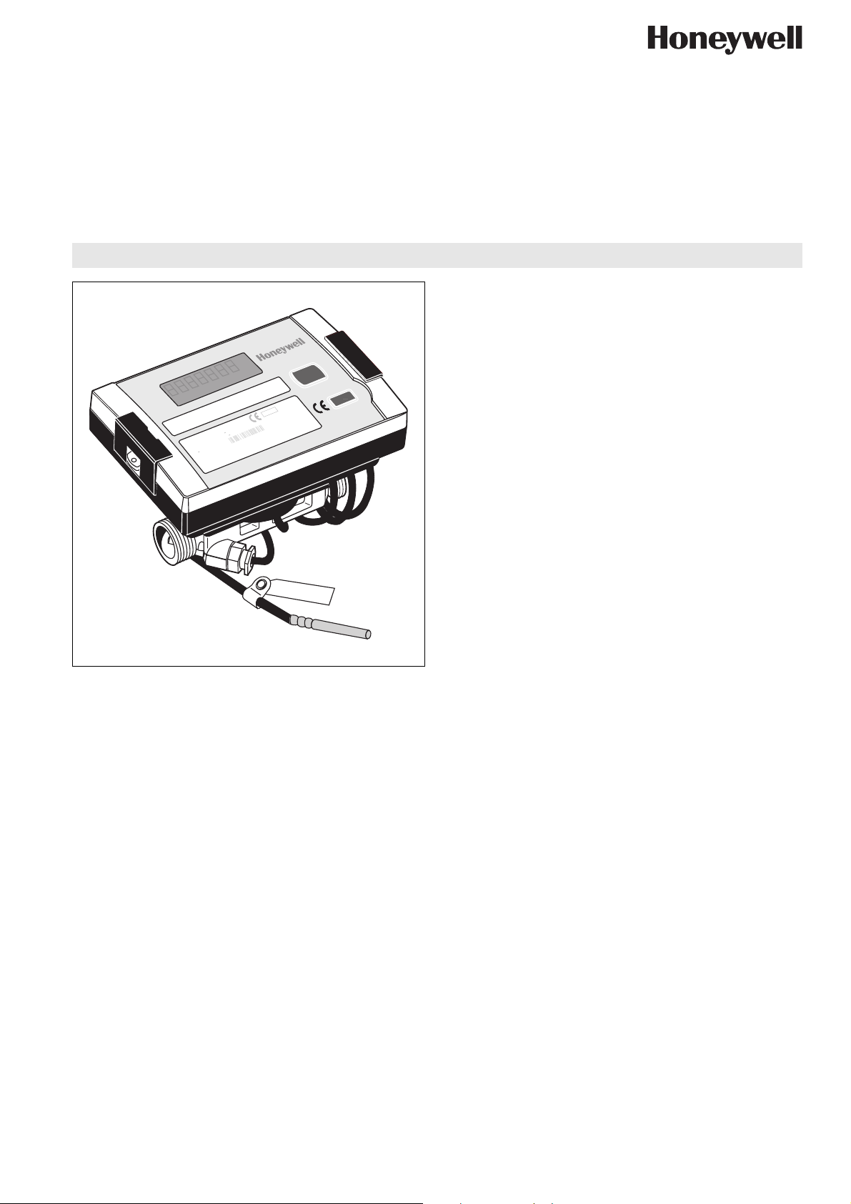
Ultrasonic Hydronic Meters
FOR HEATING AND COOLING APPLICATIONS
0102
M 07
DE-06-MI004-PTB017
500
Hydrometer
O: 3.....177K
Environm. class: E1
Mechanical class: M1
Metrological class:
heatmeter
Inst. place: low temp.
Prod.year: 2007
5N: 3400
2
6446
qi: 0.015m
qp: 1.5m
qs: 3m
O: 5.....130
DN: 15 IP 54
T.sensor: Pt
O: 0.....180°C
3
∆
/h
3
/h
3
/h
°C
PN: 16
0
Typ: 773
7730000
EW7730K1200
Design
Hydronic meters of the EW773 Series consist of:
• Electronic energy integrator with cable connection to the
ultrasonic volume measuring component, supply and return
temperature probe
• Ultrasonic volume measuring component with external
threads according to ISO228 (DN15...DN25) or flanges
(DN25…DN80)
Materials
• Housing of electronic energy integrator made of black and
transparent plastic
• Housing of ultrasonic volume measuring component made of
brass
EW773 Series
PRODUCT DATA
Application
Static compact hydronic meter with electronic measurement
based on the ultrasonic principle, consisting of electronic
energy integrator, ultrasonic volume measuring component and
temperature sensors.
Metering of hydronic heating and / or cooling energy in hydronic
systems based on volume, supply and return temperature.
EW7730 models are suitable for energy metering of heating
systems.
EW7731 models are suitable for energy metering of cooling
and combined cooling and heating systems.
Features
• MID approval
• First approval in Europe for ultrasonic heat meter with
dynamic range of qi/qp m³/h 1:250 in class 2 (qp 1.5 /
2.5 / 6.0m³/h)
• Complete dynamic range ≥ 1:1,500
• 12 years battery lifetime
• Meters up to qp 6 with patented free-beam principle and
robust swirl-free flow around reflector made of stainless
steel
• Meters qp10 and larger with direct beam principle
• Standard housing dimensions
• Can be used for heating (EW7730), cooling or both
(EW7731)
• Available in nominal sizes from qp 0.6 up to 40m³/h
• Measuring accuracy meets the requirements of EN1434
class 2 and 3
• No calming leg required on inlet or outlet for sizes up to
qp 0.6m³/h
• Power save mode
• Remote reading via M-Bus, RF, RS232 or optical interface
• Optional plug and play modules
• Individual tariff functions
• History memory for 24 months
• Extensive diagnostic displays
• Windows based HYDRO-SET parametrization software
for optimum adaptation to the user's specific needs
Honeywell y Subject to change EN0H-2600GE25 R0809
Page 2
EW773 SERIES ULTRASONIC HYDRONIC METERS
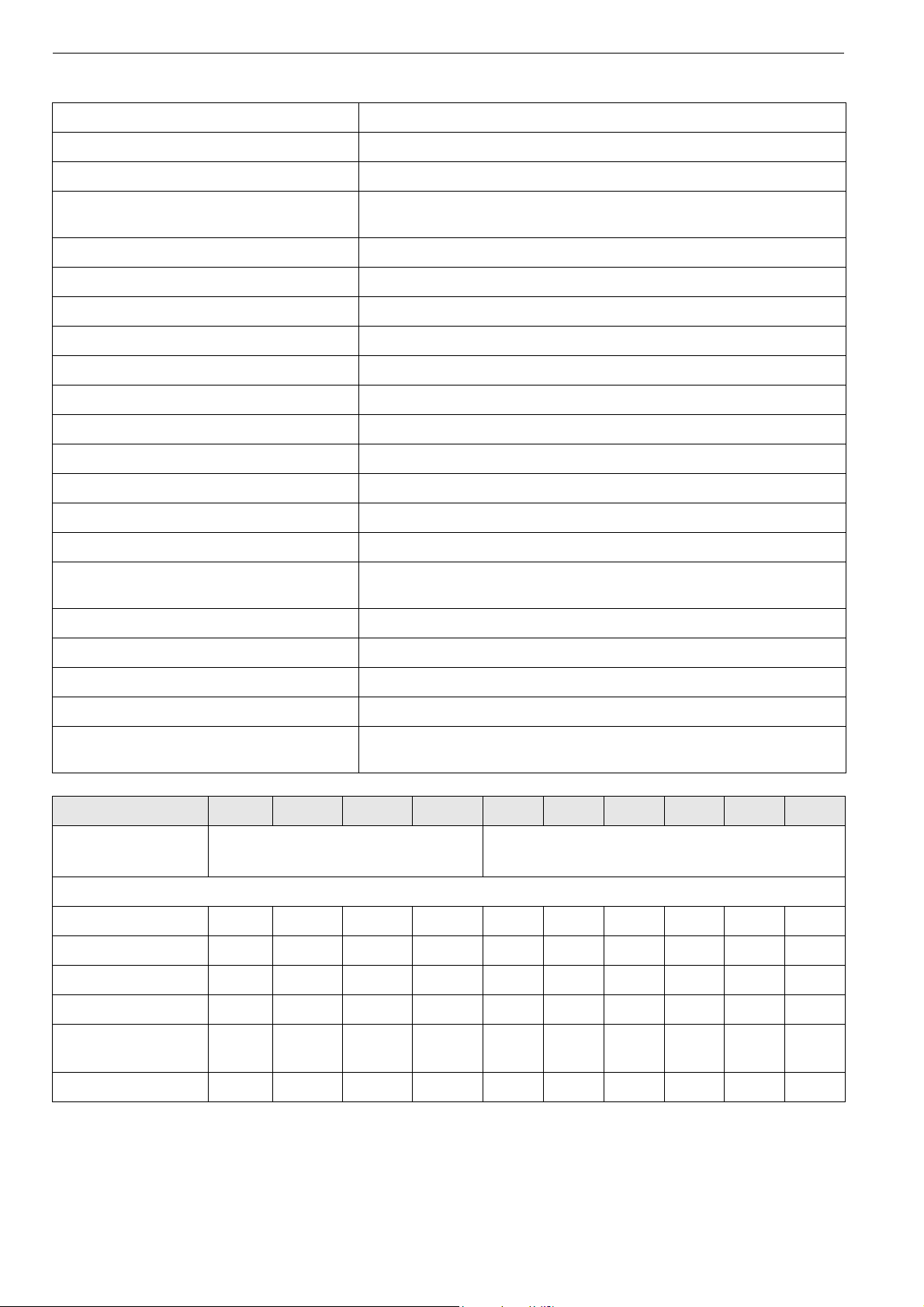
Specifications
Medium Water, quality to VDI2035
Medium temperature see table below
Ambient temperature 0…55°C (32…131°F)
Operating pressure Threaded versions: PN16
Flanged versions: PN25
kvs (cv)-values see table below
Ambient class EN1434 class C / A
Protection class IP54 / IP64 (EW7731 volume measuring component only)
Type Static heat meter to EN1434
Measuring process Ultrasonic volume measurement
Display LCD, 7-digit
Units MWh – kWh – GJ – Gcal – MBtu
Total values 9 999 999 – 999 999.9 – 99 999.99 – 9 999.999
Values displayed Power – Energy – Flow rate – Temperature
Temperature sensors Pt500 with 2-wire leads
Sensor current Pt500 peak < 2; rms < 0.012mA
Measuring cycle Battery supply: 16s
Mains unit supply: 1s
Max. temperature difference 177K
Min. temperature difference 3K
Starting temperature difference 0.25K
Absolute temperature measuring range -9.9…189.9°C (14.2…373.8°F)
Operating voltage qp0.6…6: 3.0V lithium battery
qp10…40: 3.6V lithium battery
qp 0.6 1.0 1.5 2.5 3.5 6.0 10 15 25 40
Medium
temperature
EW7730: 20…130°C (68…266°F)
EW7731: 5…130°C (41…266°F)
EW7730: 20…150°C (68…302°F)
EW7731: 5…150°C (41…302°F)
Flow rates
Maximum (qs) m
Nominal (qp) m
3
/h1.2 2 3 5 7 1220305080
3
/h 0.6 1 1.5 2.5 3.5 6 10 15 25 40
Minimum (qi) l/h 6 10 6 10 35 24 40
1
/100 150 250 400
Starting l/h 1 2.5 2.5 4 7 7 15 30 50 80
kvs (cv)-value m3/h 2.06
(2.41)
5.27
(6.17)
5.48
(6.41)
7.91
(9.25)
16.7
(19.5)
16.8
(19.7)
32.5
(38.0)
61.2
(71.6)
94.5
(111)
127
(149)
∆p at qp mbar 85 36 75 100 44 128 95 60 70 100
NOTE: Medium temperature may be limited by installation position, see chapter 'Installation' on page 6.
1
when mounted in horizontal position
EN0H-2600GE25 R0809 2 Honeywell y Subject to change
Page 3

Function
Integrator
The integrator contains all the necessary circuits for recording
flow rate and temperature and for calculating, logging and
displaying the data. The integrator housing can be mounted
directly onto the volume measuring component or to the wall.
The meter can be conveniently read from a single line sevendigit display with units and symbols. A pushbutton provides
user friendly control of the various display loops. All failures
and faults are recorded automatically and displayed on the
LCD screen. To protect the reading data, all relevant data is
saved in a non-volatile memory (EEPROM). This memory
saves the measured values, device parameters and types of
error at regular intervals
Ultrasonic volume measuring component
The ultrasonic technology of the volume measuring component
permits very high measuring accuracy and can be used in the
supply or return pipeline. The volume measuring component
meets the requirements of EN1434 / class 2 and 3. The standard cable length between the calculator and the volume
measuring component is 1.5m for meters up to qp 6 and 2.5m
for meters qp 10-40 (other cable lengths optionally on request).
Supply voltage:
Standard (12 year life)
• Meters up to qp 6: lithium battery 3.0V DC
• Meters qp 10-40: lithium battery 3.6V DC
Optional (please enquire):
• Meters up to qp 6: lithium battery 3.6V DC (16-year life)
• Meters up to qp 25: mains unit 230V AC or 24V AC
Temperature sensors
Pairs of Pt500 temperature sensors with 2-wire leads are used.
Interfaces
The EW773 Series is equipped as standard with a ZVEI optical
interface with the M-Bus protocol as per EN1434. This interface is used, for example, for communication with the HYDROSET parametrization software. The meter has two slots for plug
and play modules. One slot for a function module and one slot
for a communications module.
The following communication modules are available as options:
•RF module
• M-Bus module to EN1434
• RS232 module
The RS232 module is a serial interface and permits data
exchange with the heat meter. A special data cable is required
for this purpose.
The RF module communicates a list of predefined data
records. This can be edited by the HYDRO-SET software.
Pulse Input
Two additional pulse inputs are available. The pulse value and
the unit is configurable for energy, water, gas or electrical
metering by the HYDRO-SET software. Also two accounting
days are available for both inputs.
Pulse Output
The meter provides levels for two optional external pulse
outputs, which can be freely programmed using the HYDROSET software.
Possible pulse output values
• Energy (standard setting)
• Volume (standard setting)
• Tariff energy 1
• Tariff energy 2
• Tariff condition 1, limit switch
• Tariff condition 2, limit switch
EW773 SERIES ULTRASONIC HYDRONIC METERS
• Energy error
• Volume error
Module Combinations
The following module combinations for data transmission are
available ex works or for retrofitting in the field:
Function modules
• Pulse input module (2 inputs)
• Pulse output module (2 outputs)
• Pulse input module and pulse output module (1 input and 1
output)
• Combined pulse in- and output module (2 inputs / 1 output)
Communication modules
•M-Bus
• RS232
•RF
Accessories / Software
The HYDRO-SET parametrization software based on the MBus is a convenient tool for handling the hydronic meter. It runs
on Windows® 2000, and XP and is used for logs memories:
• setting up for operation
• reading out measured values
• printing of meter logs
• meter configuration
Event Memory
Events such as changes and faults are stored in a non-volatile
memory with a capacity of up to 31 entries. The following
events are recorded:
• Checksum error
• Temperature measurement error
• Ultrasonic echo time measurement errors
• Start and end of test mode
Monthly Memory
The EW773 Series has a history memory of 24 months. The
following values are stored in the EEPROM on the
programmed date 1…31 of the actual month:
• Date / Time
•Volume
• Energy
• Error day counter
• Maximum monthly flow rate
• Maximum monthly power
• Date of maximum monthly flow rate
• Date of maximum monthly power
• Tariff energy 1
• Tariff energy 2
• Tariff definition 1
• Tariff definition 2
• Impulse counter 1
• Impulse counter 2
Honeywell y Subject to change 3 EN0H-2600GE25 R0809
Page 4
EW773 SERIES ULTRASONIC HYDRONIC METERS
Log Memory
The log memory is used to store consumption values. The
storage frequency can be selected from various storage intervals (1, 2, 3, 4, 5, 6, 10, 12, 15, 20, 30, 60 minutes or the default
setting of 24 hours, see Table 1). The data saved in the log
memory can be used for the following analyses:
• Reading the meter on a certain day
• Example: if the day for reasing is 01.10 (1 October), the
meter reading is displayed for the period from 01.10 of the
previous year to 30.09 of the current year.
• Comparison of the last consumption period with the preceding period
Table 1. Extract of possible log memory settings
Storage
interval
5 minutes Error status, overload
15 minutes 440 110 hours
1 hour 440 18.3 days
24 hours 440 440 days
Values Number of
data
records
440 36.6 hours
time temperature,
overload time flow rate,
forward temperature,
return temperature,
date and time,
energy,
tariff energy 1,
tariff energy 2,
tariff definition 1,
tariff definition 2,
volume,
error day counter
Recording
period
Maximum Values
The integrator creates max. values for power and flow rate
based on consumption time, which are stored in the EEPROM.
The integration intervals are adjustable to 6, 15, 30 or 60
minutes. Default setting is 60 minutes.
Tariff Function
The integrator offers two optional tariff memories for monitoring
plant load states for limit tariffs. Extensive tariff conditions
make it possible to adapte the meter individually to the required
customer-specific applications. Apart from the energy a timebased tariff can also be programmed.
The following limit types are possible (this example applies to
the display with 3 decimal places):
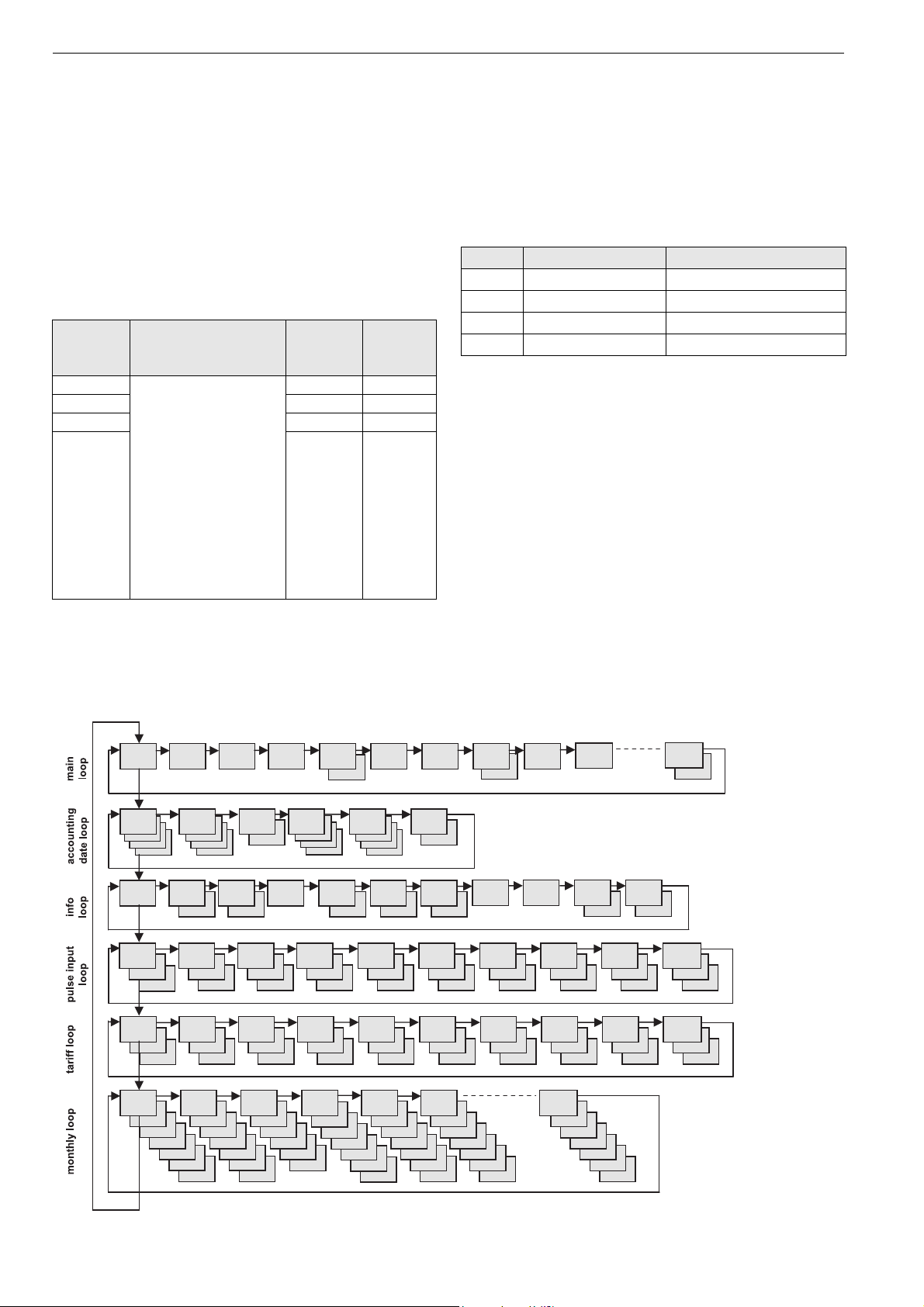
Table 2. Limit types
Type LIMIT LIMIT resolution
∆T 1 ... 190 °C 1 °C
T
P 1 ... 255 kW 1 kW
Q 100 ... 25 500 l/h 100 l/h
1 ... 190 °C 1 °C
Display Control
The readings are displayed on the meter by a 7-digit LCD with
units and symbols
Loop Structure
The EW773 Series display has six loops. Some display
windows consist of two (to maximum seven) displays that are
shown alternately at 4-second intervals.
Some pictures in the loops can be deactivated separately.
NOTE: For quick visual guidance, the loops in the display are
The main loop with the current data, e.g. for energy, volume
and flow rate, is programmed as default setting. In the standard
setting loop No. 5 (tariff loop) is not active.
numbered from 1 to 6.
Fig. 1. Loop overview
EN0H-2600GE25 R0809 4 Honeywell y Subject to change
Page 5

EW773 SERIES ULTRASONIC HYDRONIC METERS
Table 3. Display Contents
Loop Sequence Window 1 Window 2 Window 3
„1“
Main loop
Loop Sequence Window 1 Window 2 Window 3 [OFF] Window 4
„2“
Accoun-
ting date
loop
1.1 Accumulated energy
1.2 Volume
1.3 Flow rate
1.4 Power
1.5 Forward temperature Return temperatur
1.6 Difference temperature
1.7 Operating hours
1.8[OFF] Monthly peak power Date
1.9 Error code
1.10 Display test
1.11[OFF] Tariff energy 1
1.12[OFF] Tariff energy 2
1.13[OFF] ‘In 1’ Pulse input counter 1
1.14[OFF] ‘In 2’ Pulse input counter 2
2.1 Accounting date 1 Accounting date 1 energy Accounting date 1 volume ‚Accd 1’
2.2 Accounting date 1
previous year
Accounting date 1
previous year energy
Accounting date 1
previous year volume
2.3 ‚Accd 1’ Accounting date 1 in the
future
2.4 Accounting date 2 Accounting date 2 energy Accounting date 2 volume ‚Accd 2’
2.5 Accounting date 2
previous year
Accounting date 2
previous year energy
Accounting date 2
previous year volume
2.6 ‚Accd 2’ Accounting date 2 in the
future
‚Accd 1’
‚Accd 2’
Loop Sequence Window 1 Window 2 Window 3
„3“
Info loop
3.1 Current date
3.2 ‚SEC_Adr’ Secundary address
3.3 ‚Pri_Adr’ Primary address
3.4 ‚ Pt 100 r’ or ‚ Pt 500 r’
3.5 Monthly peak flow rate Date max. flow rate
3.6 Monthly peak power Date max. power
3.7 Integration interval
(maximum value)
3.8 Number of error day’s
3.9 ‚Out1’ Pulse value and unit pulse output 1
3.10 ‚Out2’ Pulse value and unit pulse output 2
Loop Sequence Window 1 Window 2 Window 3
„4“
4.1 ‚In1’ Pulse input counter 1 Pulse value 1
4.2 ‚In2’ Pulse input counter 2 Pulse value 2
Pulse
input loop
4.3[OFF] Accounting date 1 ‚In1’ Acc. date 1 Pulse value 1
4.4[OFF] Accounting date 1 ‚In2’ Acc. date 1 Pulse value 2
4.5[OFF] Accounting date 1 previous year ‚In1’ Acc. date 1 previous year
Pulse value 1
4.6[OFF] Accounting date 1 previous year ‚In2’ Acc. date 1 previous year
Pulse value 2
4.7[OFF] Accounting date 2 ‚In1’ Acc. date 2 Pulse value 1
4.8[OFF] Accounting date 2 ‚In2’ Acc. date 2 Pulse value 2
4.9[OFF] Accounting date 2 previous year ‚In1’ Acc. date 2 previous year
Pulse value 1
4.10[OFF] Accounting date 2 previous year ‚In2’ Acc. date 2 previous year
Pulse value 2
Honeywell y Subject to change 5 EN0H-2600GE25 R0809
Page 6

EW773 SERIES ULTRASONIC HYDRONIC METERS
Loop Sequence Window 1 Window 2 Window 3
„5“
Tariff
loop
5.1[OFF] Tariff energy 1 Tariff function 1 (e.g. ‚t 01’) Limit tariff 1
5.2[OFF] Tariff energy 2 Tariff function 2 (e.g. ‚t 02’) Limit tariff 2
5.3[OFF] Accounting date 1 Accounting date 1 tariff energy 1 ‚Accd 1’
5.4[OFF] Accounting date 1 Accounting date 1 tariff energy 2 ‚Accd 1’
5.5[OFF] Accounting date 1 previous year Accounting date 1 previous year
tariff energy 1
5.6[OFF] Accounting date 1 previous year Accounting date 1 previous year
tariff energy 2
5.7[OFF] Accounting date 2 Accounting date 2 tariff energy 1 ‚Accd 2’
5.8[OFF] Accounting date 2 Accounting date 2 tariff energy 2 ‚Accd 2’
5.9[OFF] Accounting date 2 previous year Accounting date 2 previous year
tariff energy 1
5.10[OFF] Accounting date 2 previous year Accounting date 2 previous year
tariff energy 2
‚Accd 1’
‚Accd 1’
‚Accd 2’
‚Accd 2’
Loop Sequence Window 1 Window 2 Window
3[OFF]
„6“
Monthly
loop
[OFF] = not active
6.1 Last month Energy Tariff energy 1 Tariff energy 2 Volume Max. flow rate Max. Power
6.2 Month –1 Energy Tariff energy 1 Tariff energy 2 Volume Max. flow rate Max. Power
6.3 Month -2 Energy Tariff energy 1 Tariff energy 2 Volume Max. flow rate Max. Power
.
.
.
6.24 Month -23 Energy Tariff energy 1 Tariff energy 2 Volume Max. flow rate Max. Power
Easy Operation
A pushbutton mounted on the front of the meter is used to
switch to the various displays. The button can be pressed for a
short or long time. A short press of the button (< 3 seconds)
switches to the next display within a loop and a long press (> 3
seconds) switches to the next display loop. The "Energy"
window (sequence 1.1) in the main loop is the basic display.
The meter switches automatically to power save mode if the
button is not pressed for approx. 4 minutes and returns to the
basic display when the button is pressed again. The loop
settings can be programmed to suit the customer's individual
requirements using the HYDRO-SET software.
Window
4[OFF]
Window 5 Window 6 Window 7
Wiring
The Volume Measuring Component and the energy meter must
be connected as follows (also see Fig. 2.):
• 9 red (+)
• 10 yellow (signal)
• 11 blue (-)
Installation
• EW773 Series hydronic meters must be installed in the return
pipeline. The correct flow direction is indicated by a flow
arrow on the flange or body.
• A calming leg of 5 x DN before the meter is required for sizes
qp10 and higher.
• The max. medium temperature is as follows:
• 130°C when horizontally mounted and electronics (black
enclosure) turned sideways for sizes qp=0.6...2.5m³/h, or
• 150°C when horizontally mounted and electronics turned
sideways for sizes qp=3.5...40m³/h
• 120°C when horizontally mounted and electronics turned
upwards
• 120°C when vertically mounted
• In any case the energy counter must be separated from the
volume measuring unit if the medium temperature exceeds
90°C"
• The energy calculator can be installed on the meter or separate from the meter.
• The volume measuring component and the energy calculator
of meters up to qp6 are connected by a permanently fixed
cable with a length of 1.5m.
• The cable between the the volume measuring component
and the energy calculator of meters qp10 and larger has to
be installed, wiring instructions see below.
• During measurement the meter must be completely filled with
water.
EN0H-2600GE25 R0809 6 Honeywell y Subject to change
Fig. 2. Wiring
Page 7

Dimensions
EW773 SERIES ULTRASONIC HYDRONIC METERS
150
50
R
G
L
L1
H
h
L
Fig. 3. Dimensions qp=0.6...10m3/h
∅d
B
∅
D
F
3
Fig. 4. Dimensions qp=15...40m
NOTE: All dimensions in mm unless stated otherwise.
Table 4. Dimensions
Nominal size qp [m3/h] 0.6/1.0/1.5 2.5 3.5 6.0 10 15 25 40
DN size 15 20 25 25 25 32 40 50 65 80
Body length L [mm] 110 130 260 260 260 260 300 270 300 300
Overall length with
fittings
Height of pipe axis to
top of electronics
Height of pipe axis to
bottom of valve
housing
Body thread G [inch] G3/4B G1B G1 1/4B Flanged G1 1/4B Flanged Flanged Flanged Flanged Flanged
Fitting thread
(accessory)
Flange diameter D [mm] 114 139 148 163 184 198
L1 [mm] 190 230 380 380
H [mm] 78 80 84.5 84.5 84.5 84.5 90 91 91 91
h [mm] 14.5 18 23 23
R [inch] R1/2 R3/4 R1 R1
/h
Flange dimension F [mm] 100 125 138 147 170 188
Bolt circle diameter d [mm] 85 100 110 125 145 160
Weight [kg] 0.76 0.85 1.5 3.5 1.5 4.8 7.0 8.5 10.8 12.6
NOTE: Threaded tailpieces are not supplied with the heat meter
Honeywell y Subject to change 7 EN0H-2600GE25 R0809
Page 8

EW773 SERIES ULTRASONIC HYDRONIC METERS
Ordering Information
Table 5. Order Specification Overview
Size qp DN size Length Connection Interface OS-No. EW7730 OS-No. EW7731
3
/h DN15 110mm G3/4B None EW7730A0100 EW7731A0100
0.6m
3
/h DN15 110mm G3/4B None EW7730A0600 EW7731A0600
1.0m
3
/h DN15 110mm G3/4B None EW7730A1200 EW7731A1200
1.5m
3
/h DN20 130mm G1B None EW7730A2000 EW7731A2000
2.5m
3
/h DN20 260mm G1 1/4B None EW7730A2800 EW7731A2800
3.5m
3
/h DN25 260mm Flanges PN25 None EW7730A3000 EW7731A3000
3.5m
3
/h DN20 260mm G1 1/4B None EW7730A3600 EW7731A3600
6.0m
3
/h DN32 260mm Flanges PN25 None EW7730A4000 EW7731A4000
6.0m
3
/h DN40 300mm Flanges PN25 None EW7730A4800 EW7731A4800
10m
3
/h DN50 270mm Flanges PN25 None EW7730A5200 EW7731A5200
15m
3
/h DN65 300mm Flanges PN25 None EW7730A6000 EW7731A6000
25m
3
/h DN80 300mm Flanges PN25 None EW7730A7000 EW7731A7000
40m
3
0.6m
/h DN15 110mm G3/4B M-Bus EW7730M0100 EW7731M0100
3
/h DN15 110mm G3/4B M-Bus EW7730M0600 EW7731M0600
1.0m
3
/h DN15 110mm G3/4B M-Bus EW7730M1200 EW7731M1200
1.5m
3
/h DN20 130mm G1B M-Bus EW7730M2000 EW7731M2000
2.5m
3
/h DN20 260mm G1 1/4B M-Bus EW7730M2800 EW7731M2800
3.5m
3
/h DN25 260mm Flanges PN25 M-Bus EW7730M3000 EW7731M3000
3.5m
3
/h DN20 260mm G1 1/4B M-Bus EW7730M3600 EW7731M3600
6.0m
3
/h DN32 260mm Flanges PN25 M-Bus EW7730M4000 EW7731M4000
6.0m
3
/h DN40 300mm Flanges PN25 M-Bus EW7730M4800 EW7731M4800
10m
3
/h DN50 270mm Flanges PN25 M-Bus EW7730M5200 EW7731M5200
15m
3
/h DN65 300mm Flanges PN25 M-Bus EW7730M6000 EW7731M6000
25m
3
/h DN80 300mm Flanges PN25 M-Bus EW7730M7000 EW7731M7000
40m
3
0.6m
/h DN15 110mm G3/4B M-Bus+2 pulse inputs EW7730K0100 EW7731K0100
3
/h DN15 110mm G3/4B M-Bus+2 pulse inputs EW7730K0600 EW7731K0600
1.0m
3
/h DN15 110mm G3/4B M-Bus+2 pulse inputs EW7730K1200 EW7731K1200
1.5m
3
/h DN20 130mm G1B M-Bus+2 pulse inputs EW7730K2000 EW7731K2000
2.5m
3
/h DN20 260mm G1 1/4B M-Bus+2 pulse inputs EW7730K2800 EW7731K2800
3.5m
3
/h DN25 260mm Flanges PN25 M-Bus+2 pulse inputs EW7730K3000 EW7731K3000
3.5m
3
/h DN20 260mm G1 1/4B M-Bus+2 pulse inputs EW7730K3600 EW7731K3600
6.0m
3
/h DN32 260mm Flanges PN25 M-Bus+2 pulse inputs EW7730K4000 EW7731K4000
6.0m
3
/h DN40 300mm Flanges PN25 M-Bus+2 pulse inputs EW7730K4800 EW7731K4800
10m
3
/h DN50 270mm Flanges PN25 M-Bus+2 pulse inputs EW7730K5200 EW7731K5200
15m
3
/h DN65 300mm Flanges PN25 M-Bus+2 pulse inputs EW7730K6000 EW7731K6000
25m
3
/h DN80 300mm Flanges PN25 M-Bus+2 pulse inputs EW7730K7000 EW7731K7000
40m
Scope of Delivery
• EW773 Series heat meter with supply and return temperature sensor
• 2 sealings
• Fitting for installation of supply temperature sensor
• Wall mounting plate
• Operating and setup instructions
EN0H-2600GE25 R0809 8 Honeywell y Subject to change
Page 9

Accessories
Union nut, sealing and externally threaded red bronze tailpiece for external threads
DN 15 VA7401A015
DN 20 VA7401A020
DN 25 VA7401A025
Sanpress red bronze compression-fitting with sealing
DN15, for 15 mm pipe-Ø VA7404A015
DN15, for 18 mm pipe-Ø VA7404A018
DN20, for 22 mm pipe-Ø VA7404A020
DN25, for 28 mm pipe-Ø VA7404A025
Union nut, sealing and internally threades red bronze tailpiece
DN 15 VA7405A015
DN 18 VA7405A018
DN 20 VA7405A020
DN 25 VA7405A025
Ballvalve with connection for supply temperature probe
G1/2“ internal thread EWA087HY004
G3/4“ internal thread EWA087HY005
G1“ internal thread EWA087HY006
Ballvalve with two side connections G1/4" internal thread
and one blind stop
G1/2" internal threads VB550SY2015
G3/4" internal threads VB550SY2020
G1" internal threads VB550SY2025
G1 1/4" internal threads VB550SY2032
G1 1/2" internal threads VB550SY2040
NOTE: Only available in packing units of 6 pcs or 8 pcs (3/4")
For connection of supply temperature sensor adapter
EWA354830 is required
EW773 SERIES ULTRASONIC HYDRONIC METERS
Tailpiece for connection of supply temperature sensor
R1/2 external thread,
M10x1 sensor thread
G1/4" external thread,
M10x1 sensor thread
Brass immersion pockets (for use with MID meters)
35mm EWA3002684
52mm EWA3002685
85mm EWA3004406
120mm EWA3004407
Modules
M-Bus communication
module (for upgrade of
EW773xA types)
Pulse output module
(2 outputs)
Pulse input module
(2 inputs)
RF communication module EWA54200017
Combined pulse in- and
output module
RS232 interface module
with cable
EWA087HY003
EWA354830
EWA54200001
EWA54200002
EWA54200003
EWA54200026
EWA54200030
Measuring Accuracy
Fig. 5. Measuring accuracy to EN1434 Class 2
Honeywell y Subject to change 9 EN0H-2600GE25 R0809
Page 10

EW773 SERIES ULTRASONIC HYDRONIC METERS
Flow Diagram
100,6 1.0 1.5 2.5 3.5 6.0 15 25 40
Fig. 6. Pressure drop diagram
400000
50
EN0H-2600GE25 R0809 10 Honeywell y Subject to change
Page 11

EW773 SERIES ULTRASONIC HYDRONIC METERS
Honeywell y Subject to change 11 EN0H-2600GE25 R0809
Page 12

EW773 SERIES ULTRASONIC HYDRONIC METERS
Environmental and Combustion Control
Honeywell GmbH
Hardhofweg
74821 Mosbach, Germany
Phone: +49 (6261) 810
Fax: +49 (6261) 81393
www.honeywell.com
EN0H-2600GE25 R0809
August 2009
© 2009 Honeywell International Inc.
Subject to change without notice
Manufactured for and on behalf of the Environmental and Combustion
Controls Division of Honeywell Technologies Sàrl, Rolle, Z.A. La
Pièce 16, Switzerland or its authorized representative.
 Loading...