

Honeywell DT-6360STC Installation Instructions Manual
Model DT-6360STC
Ceiling Mount Motion Sensor
INSTALLATION INSTRUCTIONS
MOUNTING LOCATION
The DUAL TEC® 6360STC motion sensor provides maximum
coverage when mounted on ceilings from 8' (2.4 m) to 16' (4.8 m)
high. Refer to the
passive infrared (PIR) mirror assembly to use at different ceiling
heights.
Choose a mounting location in the center of the protected area.
The protected area should be free of objects that might prevent
the PIR sensor from detecting an intruder: large pieces of
furniture, room dividers, etc.
Remember, infrared energy cannot penetrate solid objects. If the
PIR detector is blocked, the DT-6360STC will not trigger an alarm.
Note: If you plan to use the DT-6360STC's tamper switches,
read the
MOUNTING PROCEDURE
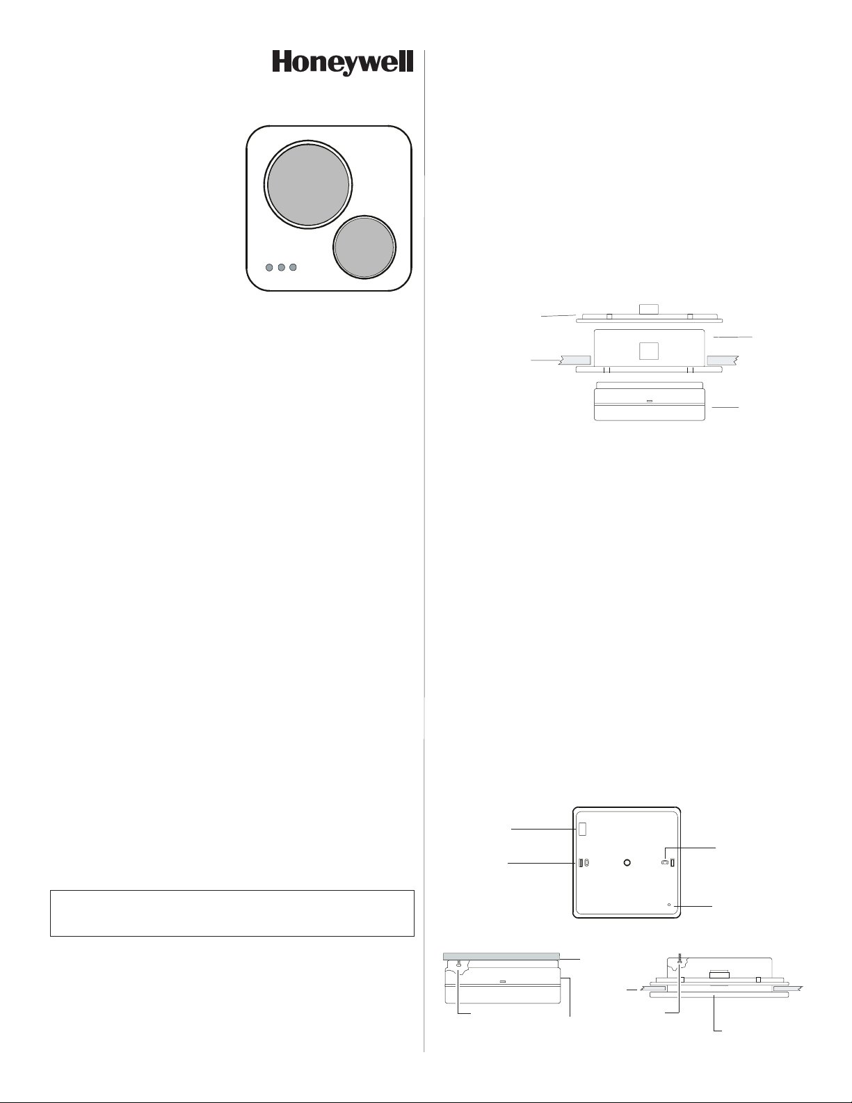
To remove the front cover, orient the DT-6360STC so that one of
the sides with the small rectangular slot in the center is visible.
Using a small flathead screwdriver, gently push down on the slot
while separating the housing parts. Set the front cover aside.
Remove the printed circuit board (PCB) by depressing one of
the retaining brackets at its sides. Use the microwave antenna
to carefully pull the PCB out.
Surface Mounting
If mounting the DT-6360STC directly on a ceiling, use the back
cover as a template to mark holes for the mounting screws and
wiring. Drill the holes. Then pull several inches of wiring from
the ceiling through the center hole in the back housing.
Attach the back housing to the ceiling with the mounting screws.
Recommended mounting screws: #6 (M3.5) pan head.
Note: If surface wiring, use the knockout hole on the side of the
housing.
System Set-up section to determine which
Tamper Installation section on page 1.
To flush mount the unit, cut a 5.5" x 5.5" (14 cm x 14 cm) hole in
the ceiling. Insert the recess bucket into the hole, using it as a
template to mark drill holes for the four mounting screws.
Remove the bucket and drill the screw holes.
If using the retainer ring, place it through, then directly over, the
hole in the ceiling tile. Make sure to orient the retainer ring
and recess bucket as shown in Figure 1.
Next, attach the back housing of the DT-6360STC to the inside
of the recess bucket, using the same screw holes and screws
used for surface mounting [#6 (M3.5) pan head]. Pull several
inches of wiring from the ceiling through the center hole in the
recess bucket and DT-6360STC back housing.
Insert the recess bucket into the hole in the ceiling, securing it to
the ceiling (and retainer bracket) with four mounting screws.
RETAINER
RING
CEILING
Figure 1
DT-6360STC
Flush Mounting Kit
RECESS
BUCKET
DT-6360STC
Tamper Installation
The DT-6360STC is equipped with two tamper switches: a cover
tamper and ceiling tamper. When the tamper switches are used,
removing the cover from the sensor will activate the cover tamper;
removing the sensor from the ceiling will activate the ceiling
tamper. Both tamper switches are normally closed (NC) and
internally wired in series.
The cover tamper switch can be used without the ceiling tamper
and requires no modifications to the DT-6360STC housing.
To use the ceiling tamper, remove the square knockout in the rear
housing (directly behind the ceiling tamper switch), then install a
screw* in the ceiling. Leave enough of the screw protruding to
depress the tamper switch. Refer to Figure 2.
If the installation is recessed, remove the knockout from the rear
housing, drill a screw hole (behind the knockout) in the recess
bucket, then install the screw* in the recess bucket. Leave
enough of the screw protruding to depress the tamper switch.
Refer to Figure 2.
Figure 2
*Note: #6 (M3.5)
pan head is
recommended.
KNOCKOUT
LATCH
REAR HOUSING
Cover and Ceiling
Tamper Switches
KEYHOLE
IMPORTANT: To ensure insects do not get inside the DT6360STC housing, make sure to seal all holes. (Recommended
sealant: silicone RTV.)
Flush Mounting
The DT-6360STC is shipped with a special kit for flush mounting. The kit contains a recess "bucket" and retainer ring. The
retainer ring is only needed when flush mounting the unit in
ceiling tile. Removing the tile from the ceiling (if possible) will
make the installation process easier.
- 1 -
SURFACE MOUNT
Screw
to depress
tamper
CEILING
DT-6360STC
CEILING
Screw
to depress
tamper
PIN FOR PCB
FLUSH MOUNT
DT-6360STC inside
recess bucket
Removing Front Cover After Installation (flush mount)
After installing and walk-testing the DT-6360STC flush mount, you
may need to make adjustments. Use a screwdriver to reopen the
front cover.
Insert the screwdriver as far as it will go in the grooves inside the
recess bucket. Gently press outward to release the latches
holding the front cover in place.
SYSTEM TESTING
DT-6360STC sensors are equipped with two diagnostic LEDs:
green for PIR and yellow for microwave. The red LED is used to
indicate an alarm condition.
Apply power to the sensor and wait until self-test is completed (90
seconds). Begin walk-testing after all three LEDs have gone out.
WIRING
Observing the proper polarity, wire the sensor as shown below
(use 22 to 14 AWG).
OPEN COLLECTOR
TROUBLE OUTPUT
Vce .3V max @ 50 mA.
1K series
protection resistor.
Figure 3
Wiring
Diagram
1
The Trouble Output is activated when a self-test failure or an INFORMER® condition occurs.
Refer to THE INFORMER CIRCUIT and the TROUBLESHOOTING sections.
2
EOL = End-of-Line (spare) terminal.
Note: Do not leave excess wire inside the unit. Push as much wire as
possible into the ceiling when returning the PCB to its housing.
Note: For proper wiring methods, refer to National Electrical Code NFPA
70.
Note: Reverse polarity will not damage the unit.
ALARM RELAY
1
EOL
TAMPER SWITCH
Normally Closed
(NC) with cover on
25 mA, 30 VDC.
TBL
125 mA, 25 VDC. 22 ohm
series protection resistor.
122
NC COM
CMD
REMOTE LED ENABLE or
COMMAND INPUT
(Self-Test Initiate) Active
Low 0 to 1.5 V Inactive
High 6 to V+ Input
Impedance 110 Kohms
(minimum).
EOL
NO
V-
V+
POWER
At 12 VDC,
typically
40 mA;
maximum
50 mA
SYSTEM SET-UP
Changing the PIR Mirror Assembly
The DT-6360STC package contains two PIR mirror assemblies:
one for ceilings from 8' (2.4m) to 11' (3.3m) high, another for ceilings
from 12' (3.65m) to 16' (4.8m) high. The unit is shipped with the 8'-
11' (2.4m-3.3m) mirror installed.
To change the mirror assembly, remove the front cover and turn it
over. Next, remove the protective cap and existing mirror assembly
by depressing the four retaining latches at their sides. Store (or
discard) the existing mirror and install the new one. Snap the
protective cap back into place, then replace the front cover.
PIR Masking
To eliminate specific PIR zones from the pattern, mask corresponding segments on the PIR mirror with the adhesive-backed
masking tape provided. Remember, segments to be masked
will be on the side of the mirror OPPOSITE the unwanted zones.
See Figure 4.
Once the tape has been applied, walk-test the sensor to ensure
that the correct mirror segments have been masked.
PIR MASKING
MATERIAL
PLACED HERE
MICROWAVE RANGE
THUMBWHEEL R32 (set to
INSTALLER INITIATED
SELF-TEST
MOMENTARY SHORT
INSTALL JUMPER W3
TO DISABLE TROUBLE
OUTPUT WHEN AN
INFORMER CONDITION
OCCURS (jumper is
factory installed)
REMOTE LED ENABLE
or COMMAND INPUT
Jumper W4 installed:
CMD terminal functions as Remote LED Enable.
Jumper W4 removed:
CMD terminal functions as Command Input.
(Set to Command Input
at factory)
Red - During normal operation LED illuminates when an ALARM condition is triggered.*
Yellow - During normal operation LED flashes ON when a MICROWAVE event is detected.*
Green - During normal operation LED flashes ON when a PIR event is detected.* (PIR Zone Finder)
* If Self-Test fails or an INFORMER condition occurs, LEDs indicates nature of problem (see Tables 1,2 & 3)
maximum at factory)
MAX
R32
W3
W4
TAMPER SWITCH
ALARM & DIAGNOSTIC LEDs:
TOP
W1
BOTTOM
Figure 5
DT-6360STC PCB
PLACE JUMPER W1
TO DETERMINE PIR
SENSITIVITY
(jumper set to
normal at factory;
see page 3)
REMOVE JUMPER
W2 TO DISABLE
DIAGNOSTIC LEDS
AND ALARM LED
W2
(jumper is factory
installed)
RED
YELLOW
GREEN
Microwave Range Adjustment
DT-6360STC sensors are equipped with a microwave range
thumbwheel (R32) for range adjustment. (Refer to Figure 5.)
Set the range at MINIMUM by turning the thumbwheel all the
way to the left.
As you perform the walk-test, gradually turn the thumbwheel to
the right to increase the microwave sensitivity until the desired
ranged is obtained.
Walk-test
Walk across the protected area at the ranges to be covered.
Two to four normal steps make the diagnostic LEDs light, and
the red LED should indicate an alarm condition. When there is
no motion in the protected area, all three LEDs should be off.
COMMAND INPUT / REMOTE LED ENABLE
Position W4 determines what function the Command Input
(CMD) terminal will provide.
Installing a jumper at position W4 makes the CMD terminal
function as a Remote LED Enable terminal. If the signal to the
Remote LED Enable terminal is low, the LEDs are enabled. If
the signal to the terminal is high, the LEDs are disabled.
However, if a self-test error occurs, the LEDs will light regardless
of the state of the signal.
WILL BLOCK ZONES
HITTING HERE
Figure 4
Masking the PIR
Mirrors
The CMD terminal functions as a Command Input terminal when
the jumper is removed from position W4. A momentary low
signal to the terminal (at least .5 seconds) will initiate the selftest.
LED DISABLE (Local)
To disable the diagnostic LEDs and alarm LED, remove the
jumper from position W2 on the PCB. (See Figure 5.)
- 2 -
 Loading...