

Page 1
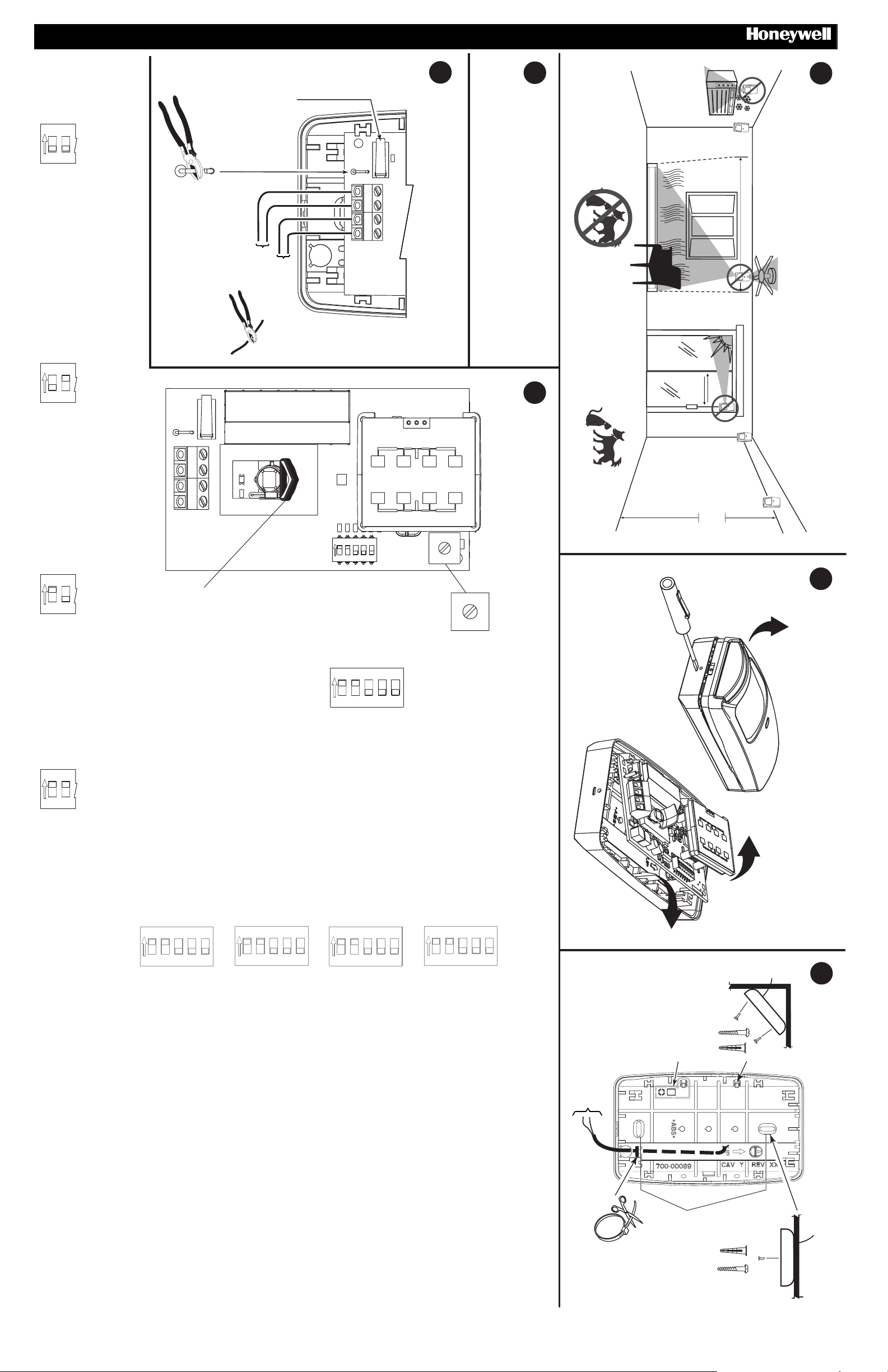
Lowest Sensitivity: 3 - 5 Steps; Up to 45 kg (100 lb) Pet Immunity
Lowest Sensitivity: 3 - 5 Steps; Up to 45 kg (100 lb) Pet Immunity
Lowest Sensitivity: 3 - 5 Steps; Up to 45 kg (100 lb) Pet Immunity
Lowest Sensitivity: 3 - 5 Steps; Up to 45 kg (100 lb) Pet Immunity
Lowest Sensitivity: 3 - 5 Steps; Up to 45 kg (100 lb) Pet Immunity
DT7500SN V-PlexTM DUAL TEC
Cover Tamper Switch
Contact AP du capot
Interruttore tamper sul
coperchio
Tamper de la cubierta
Cover Tamper Switch
Motion Sensor - Installation Instructions
5
4
1
OFF
OFF
BOARD
PLACA DE CIRCUITO IMPRESO / REPLACE CIRCUIT
RIPOSIZIONARE IL CIRCUITO / VOLVER A COLOCAR LA
WIRE / CABLAGE / COLLEGAMENTO / CABLEADO / WIRE
ON
REPLACE CIRCUIT BOARD / REMISE EN PLACE DU PCB /
Wide Angle Lens (installed)
Wide Angle Lens (installed)
Wide Angle Lens (installed)
Wide Angle Lens (installed)
Wide Angle Lens (installed)
LOCATION / EMPLACEMENT / POSIZIONAMENTO / LOCALIZACIÓN / LOCATION
W
2
1
With SMB10T
With SMB10T
With SMB10T
With SMB10T
With SMB10T
With SMB10T
10mA
24 VDC,
TAMPER
SMB-10T
Polling Loop
9 - 13VDC
Low Sensitivity: 2 - 4 Steps; Up to 23 kg (50 lb) Pet Immunity
Low Sensitivity: 2 - 4 Steps; Up to 23 kg (50 lb) Pet Immunity
Low Sensitivity: 2 - 4 Steps; Up to 23 kg (50 lb) Pet Immunity
Low Sensitivity: 2 - 4 Steps; Up to 23 kg (50 lb) Pet Immunity
Low Sensitivity: 2 - 4 Steps; Up to 23 kg (50 lb) Pet Immunity
ON
2
1
W
W
T
T
VV+
Pet Immune Lens (included)
Pet Immune Lens (included)
Pet Immune Lens (included)
Pet Immune Lens (included)
Pet Immune Lens (included)
6
a
APPROPRIATE SETTINGS
E SELEZIONARE LE IMPOSTAZIONI APPROPRIATE / IDENTIFICAR LOS COMPONENTES Y SELECCIONAR LA CONFIGURACIÓN ADECUADA / IDENTIFY COMPONENTS AND SELECT
IDENTIFY COMPONENTS AND SELECT APPROPRIATE SETTINGS / IDENTIFICATION DES COMPOSANTS ET SÉLECTION DES PARAMÈTRES APPROPRIÉS / IDENTIFICARE I COMPONENTI
OFF
T
T
-
+
Medium Sensitivity: 1 - 3 Steps; No Pet Immunity
Medium Sensitivity: 1 - 3 Steps; No Pet Immunity
Medium Sensitivity: 1 - 3 Steps; No Pet Immunity
Medium Sensitivity: 1 - 3 Steps; No Pet Immunity
Medium Sensitivity: 1 - 3 Steps; No Pet Immunity
ON
Look-Down Mask (install as shown when using Pet Immune Lens)
Look-Down Mask (install as shown when using Pet Immune Lens)
Look-Down Mask (install as shown when using Pet Immune Lens)
Look-Down Mask (install as shown when using Pet Immune Lens)
2
1
High Sensitivity: 1 - 2 Steps; No Pet Immunity
High Sensitivity: 1 - 2 Steps; No Pet Immunity
High Sensitivity: 1 - 2 Steps; No Pet Immunity
High Sensitivity: 1 - 2 Steps; No Pet Immunity
High Sensitivity: 1 - 2 Steps; No Pet Immunity
Look-Down Mask (install as shown when using Pet Immune Lens)
The sensor will respond to all communications with the
host panel armed or disarmed.
The sensor will not transmit or indicate intrusion alarms
when the panel is disarmed; in the armed state, the sensor
will respond to all communications to or with the host panel.
If installed with a Standard V-Plex
TM
Panel:
If installed with a Smart V-Plex
TM
Panel:
LED
ON
234
1
OFF
High Sensitivity
Pulse Count 1
ON
1
OFF
Pulse Count 2
Low Sensitivity
5
Microwave Walk Test ON
Anti-Mask ON
LED Enabled
234
5
LED Disabled
Microwave Walk Test OFF
Anti-Mask OFF
25%
100%
Regolazione della portata
Ajuste del rango de detección
Range Adjustment
50%
75%
Range Adjustment
Réglage de la portée hyper
2.1 - 2.4 m
(7 - 8 ft)
2
OPEN / OUVERTURE / APERTURA / APERTURA / OPEN
1
OFF
ON
2
1
3
High Sensitivity
Pulse Count 1
LED Enabled
Microwave Walk Test ON
Anti-Mask ON
Pulse Count 1
Microwave Walk Test ON
High Sensitivity
LED Enabled
Anti-Mask ON
High Sensitivity
Pulse Count 1
LED Enabled
Microwave Walk Test ON
Anti-Mask ON
Pulse Count 1
Microwave Walk Test ON
High Sensitivity
LED Enabled
Anti-Mask ON
2
ON
234
1
OFF
Pulse Count 2
Low Sensitivity
LED Disabled
Microwave Walk Test OFF
respond to all communications with the host panel, armed or
disarmed.
in the armed state, the sensor will respond to all communications
to or with the host panel.
If installed with a Standard V-Plex
5
Anti-Mask OFF
transmit or indicate intrusion alarms when the panel is disarmed;
<PT> If installed with a Smart V-Plex
ON
234
1
OFF
Pulse Count 2
Low Sensitivity
LED Disabled
Microwave Walk Test OFF
respond to all communications with the host panel, armed or
disarmed.
in the armed state, the sensor will respond to all communications
to or with the host panel.
If installed with a Standard V-Plex
5
Anti-Mask OFF
transmit or indicate intrusion alarms when the panel is disarmed;
<ES> If installed with a Smart V-Plex
ON
234
1
OFF
Pulse Count 2
Low Sensitivity
LED Disabled
Microwave Walk Test OFF
respond to all communications with the host panel, armed or
disarmed.
in the armed state, the sensor will respond to all communications
to or with the host panel.
If installed with a Standard V-Plex
<IT> If installed with a Smart V-Plex
transmit or indicate intrusion alarms when the panel is disarmed;
ON
5
OFF
Anti-Mask OFF
disarmed.
234
1
Pulse Count 2
Low Sensitivity
If installed with a Standard V-Plex
respond to all communications with the host panel, armed or
5
LED Disabled
Microwave Walk Test OFF
Anti-Mask OFF
transmit or indicate intrusion alarms when the panel is disarmed;
in the armed state, the sensor will respond to all communications
to or with the host panel.
<FR> If installed with a Smart V-Plex
(22-16 AWG)
0.3-1.3mm
2
Rear T amper Breakaway Tab
3
Rear T amper Breakaway Tab
Rear T amper Breakaway Tab
Rear T amper Breakaway Tab
Rear T amper Breakaway Tab
MOUNT / INSTALLATION / MONTAGGIO / MONTAJE / MOUNT
TM
Panel: The sensor will
TM
Panel: The sensor will not
TM
Panel: The sensor will
TM
Panel: The sensor will not
TM
Panel: The sensor will
TM
Panel: The sensor will not
TM
Panel: The sensor will
TM
Panel: The sensor will not
Use these holes when
mounting to a standard
U.S. electrical junction box
Page 2
/
!
!b FOR PET IMMUNITY
!!
• Mount the center of the sensor at 2.3 m (7.5 feet) high.
• Set the sensor to the Lowest or Low sensitivity (see step 6a).
• Install Pet Immune lens (5-532-489-01 - see Lens Change
Instructions on page 3).
• Install the look-down mask (see Step 6a).
• Install the sensor where pets cannot come within 1.8 m (6 ft) of the
sensor by climbing on furniture or other objects.
• Aim the sensor away from stairways, furniture or other objects that
can be climbed on by pets.
• TEST the installation site to determine the exact level of attainable
animal immunity.
Note: Pet immunity characteristics for this sensor have not been verified by
Underwriter’s Laboratories, Inc.
"
" PROGRAM SENSOR SERIAL NUMBER ID
""
Each sensor has a factory-assigned serial number which must be
entered into the control panel during the zone programming procedure.
The unique serial number can be found on a bar code label on the
sensor PCB. The serial number can be entered into the control panel in
one of the following methods:
A. Download it through software (Zone definition screen of Compass
software). This is recommended for large installations and
installations where foot traffic cannot be controlled.
B. Enter the number through the keypad at the “INPUT S/N” prompt
during manual zone programming. E n sure n o ot her pol li n g de vi ces
are activated when manually entering the sensor serial number.
C. Activate the sensor twice while at the “INPUT S/N” prompt during
manual zone programm i ng.
To enter the sensor’s serial number for option B or C:
Refer to the control panel’s manual for programming instructions.
For all V-Plex
“06” for SL (Serial Polling Device) at the “INPUT TYPE” prompt. For
Smart V-Plex
At the “INPUT S/N” prompt, eith er ent er the serial num b er (an d “1” for
the loop number), or fault the sensor (wave your hand in front of the
sensor or activate the tamper), the n w a it 3-6 seco nds an d faul t th e
sensor again. The keypad will beep after each fault to confirm the signal.
The sensor should now be enrolled. If a “1” does not appear under the
“L” on the zone summary screen, press [*] and enter the loop number
manually at the next screen.
#
# NORMAL WALK TEST – 10 MINUTES
##
Normal walk test mode activates after power up mode and remains
active for 10 minutes. For an additional 10 minutes of walk test time,
remove and replace the front cover. In walk test mode, the LED is
always enabled, regardless of the LED DIP switch setting. [Note: if the
panel is not a Smart V-Plex
enabling the LED (DIP switch 3 = ON.]
Walk through the detection area and observe the LED.
If necessary, adjust the microwave range, pulse count or sensitivity
setting. (For LED activation meaning, refer to the LED Indicator table
below.)
TM
panels, enter INT FOLLOWER 04 for the Zone Type and
TM
panels press “1” (Yes) for SMART CONTACT.
TM
panel, walk test can also be done by
DT7500SN V-PlexTM DUAL TEC
Motion Sensor - Installation Instructions
!
!b FOR PET IMMUNITY <FRENCH>
!!
• Mount the center of the sensor at 2.3 m (7.5 feet) high.
• Set the sensor to the Lowest or Low sensitivity (see step 6a).
• Install Pet Immune lens (5-532-489-01 - see Lens Change
Instructions on page 3).
• Install the look-down mask (see Step 6a).
• Install the sensor where pets cannot come within 1.8 m (6 ft) of the
sensor by climbing on furniture or other objects.
• Aim the sensor away from stairways, furniture or other objects that
can be climbed on by pets.
• TEST the installation site to determine the exact level of attainable
animal immunity.
Note: Pet immunity characteristics for this sensor have not been verified by
Underwriter’s Laboratories, Inc.
"
" PROGRAM SENSOR SERIAL NUMBER ID
""
Each sensor has a factory-assigned serial number which must be
entered into the control panel during the zone programming procedure.
The unique serial number can be found on a bar code label on the
sensor PCB. The serial number can be entered into the control panel in
one of the following methods:
A. Download it through software (Zone definition screen of Compass
software). This is recommended for large installations and
installations where foot traffic cannot be controlled.
B. Enter the number through the keypad at the “INPUT S/N” prompt
during manual zone programming. En sur e n o other polling devices
are activated when manually entering the sensor serial number.
C. Activate the sensor twice while at the “INPUT S/N” prompt during
manual zone programm i ng.
To enter the sensor’s serial number for option B or C:
Refer to the control panel’s manual for programming instructions.
For all V-Plex
“06” for SL (Serial Polling Device) at the “INPUT TYPE” prompt. For
Smart V-Plex
At the “INPUT S/N” prompt, either enter the seri al num b er (an d “1” for
the loop number), or fault the sensor (wave your hand in front of the
sensor or activate the tamper), the n w a it 3-6 seco nds an d faul t th e
sensor again. The keypad will beep after each fault to confirm the signal.
The sensor should now be enroll ed. If a “1” does not appear under the
“L” on the zone summary screen, press [*] and enter the loop number
manually at the next screen.
#
# NORMAL WALK TEST – 10 MINUTES
##
Normal walk test mode activates after power up mode and remains
active for 10 minutes. For an additional 10 minutes of walk test time,
remove and replace the front cover. In walk test mode, the LED is
always enabled, regardless of the LED DIP switch setting. [Note: if the
panel is not a Smart V-Plex
enabling the LED (DIP switch 3 = ON.]
Walk through the detection area and observe the LED.
If necessary, adjust the microwave range, pulse count or sensitivity
setting. (For LED activation meaning, refer to the LED Indicator table
below.)
TM
panels, enter INT FOLLOWE R 04 fo r the Zo ne T ype and
TM
panels press “1” (Yes) for SMART CONTACT.
TM
panel, walk test can also be done by
!
!b FOR PET IMMUNITY <ITALIAN>
!!
• Mount the center of the sensor at 2.3 m (7.5 feet) high.
• Set the sensor to the Lowest or Low sensitivity (see step 6a).
• Install Pet Immune lens (5-532-489-01 - see Lens Change
Instructions on page 3).
• Install the look-down mask (see Step 6a).
• Install the sensor where pets cannot come within 1.8 m (6 ft) of the
sensor by climbing on furniture or other objects.
• Aim the sensor away from stairways, furniture or other objects that
can be climbed on by pets.
• TEST the installation site to determine the exact level of attainable
animal immunity.
Note: Pet immunity characteristics for this sensor have not been verified by
Underwriter’s Laboratories, Inc.
"
" PROGRAM SENSOR SERIAL NUMBER ID
""
Each sensor has a factory-assigned serial number which must be
entered into the control panel during the zone programming procedure.
The unique serial number can be found on a bar code label on the
sensor PCB. The serial number can be entered into the control panel in
one of the following methods:
A. Download it through software (Zone definition screen of Compass
software). This is recommended for large installations and
installations where foot traffic cannot be controlled.
B. Enter the number through the keypad at the “INPUT S/N” prompt
during manual zone programming. En sur e n o ot her polling devices
are activated when manually entering the sensor serial number.
C. Activate the sensor twice while at the “INPUT S/N” prompt during
manual zone programm i ng.
To enter the sensor’s serial number for option B or C:
Refer to the control panel’s manual for programming instructions.
For all V-Plex
“06” for SL (Serial Polling Device) at the “INPUT TYPE” prompt. For
Smart V-Plex
At the “INPUT S/N” prompt, either enter the seri al num b er (an d “1” for
the loop number), or fault the sensor (wave your hand in front of the
sensor or activate the tamper), the n w a it 3-6 seco nds an d faul t th e
sensor again. The keypad will beep after each fault to confirm the signal.
The sensor should now be enroll ed. If a “1” does not appear under the
“L” on the zone summary screen, press [*] and enter the loop number
manually at the next screen.
#
# NORMAL WALK TEST – 10 MINUTES
##
Normal walk test mode activates after power up mode and remains
active for 10 minutes. For an additional 10 minutes of walk test time,
remove and replace the front cover. In walk test mode, the LED is
always enabled, regardless of the LED DIP switch setting. [Note: if the
panel is not a Smart V-Plex
enabling the LED (DIP switch 3 = ON.]
Walk through the detection area and observe the LED.
If necessary, adjust the microwave range, pulse count or sensitivity
setting. (For LED activation meaning, refer to the LED Indicator table
below.)
TM
panels, enter INT FOLLOWER 04 for the Zone Type and
TM
panels press “1” (Yes) for SMART CONTACT.
TM
panel, walk test can also be done by
$
$ MICROWAVE WALK TEST – 10 MINUTES
$$
1. Set the Microwave Walk Test DIP switch to ON, or toggle it ON and
OFF.
2. Set Range Adjustment potentiometer to 25% and replace the cover.
3. Walk through the detection area and observe the LED.
4. If necessary, adjust the potentiometer until desired detection range is
obtained. (For LED activati o n mea nin g, refer to t he LED Indic at or
table below.)
Indicator LEDs
Condition Indicator LED
Power Up
Normal Walk Test Red ON for 3 seconds if Alarm
Microwave Walk Test Red ON if Microwave is set too high
Trouble or Anti-Mask Fast Blinking Red (LED Enabled
Slow Blinking Red (will finish within
60 seconds)
Yellow ON for 2 seconds if Microwave
event detected
Green ON for 2 seconds if PIR event
detected
Green ON if Microwave is set correctly
OFF if Microwave is set too low
or Disabled)
%%%% ANTI-MASK
When DIP switch 5 is set to ON, the sensor indicates a mask condition
(see LED Indicator table above) wh en a variet y of mate rials an d
reflective objects are placed in front of it. Follow the mounting guidelines
in step 1 to avoid false mask alarms.
To clear a mask condition, visually inspect the sensor and remove any
materials blocking the sensor’s view. The sensor will clear an anti-mask
condition when three valid alarms are detected. After a mask condition
is cleared, fully walk test the required detection area.
TROUBLESHOOTING
RED LED flashing rapidly during normal operation indicates a trouble or
an anti-mask condition. If the sensor is not masked (see step 10), either
a microwave, PIR, or temperature compensation fault is present.
Solution: Momentarily power down the sensor. If the trouble does not
clear, replace the sensor. (Please ch e ck the powe r, all wiri ng an d that
the sensor is not masked before replacing the sensor.)
$
$ MICROWAVE WALK TEST – 10 MINUTES
$$
1. Set the Microwave Walk Test DIP switch to ON, or toggle it ON and
OFF.
2. Set Range Adjustment potentiometer to 25% and replace the cover.
3. Walk through the detection area and observe the LED.
4. If necessary, adjust the potentiometer until desired detection range is
obtained. (For LED activati o n mea nin g, refer to t he LED Indic at or
table below.)
Indicator LEDs
Condition Indicator LED
Power Up
Normal Walk Test Red ON for 3 seconds if Alarm
Microwave Walk Test Red ON if Microwave is set too high
Trouble or Anti-Mask Fast Blinking Red (LED Enabled
Slow Blinking Red (will finish within
60 seconds)
Yellow ON for 2 seconds if Microwave
event detected
Green ON for 2 seconds if PIR event
detected
Green ON if Microwave is set correctly
OFF if Microwave is set too low
or Disabled)
%%%% ANTI-MASK
When DIP switch 5 is set to ON, the sensor indicates a mask condition
(see LED Indicator table above) when a variety of materials and
reflective objects are placed in front of it. Follow the mounting guidelines
in step 1 to avoid false mask alarms.
To clear a mask condition, visually inspect the sensor and remove any
materials blocking the sensor’s view. The sensor will clear an anti-mask
condition when three valid alarms are detected. After a mask condition
is cleared, fully walk test the required detection area.
TROUBLESHOOTING
RED LED flashing rapidly during normal operation indicates a trouble or
an anti-mask condition. If the sensor is not masked (see step 10), either
a microwave, PIR, or temperature compensation fault is present.
Solution: Momentarily power down the sensor. If the trouble does not
clear, replace the sensor. (Please ch e ck the powe r, all wiri ng an d that
the sensor is not masked before replacing the sensor.)
DETECTION PATTERNS / COUVERTURE DE DETECTION / DIAGRAMMA DI COPERTURA /
PATRON DE DETECCIÓN / DETECTION PATTERNS
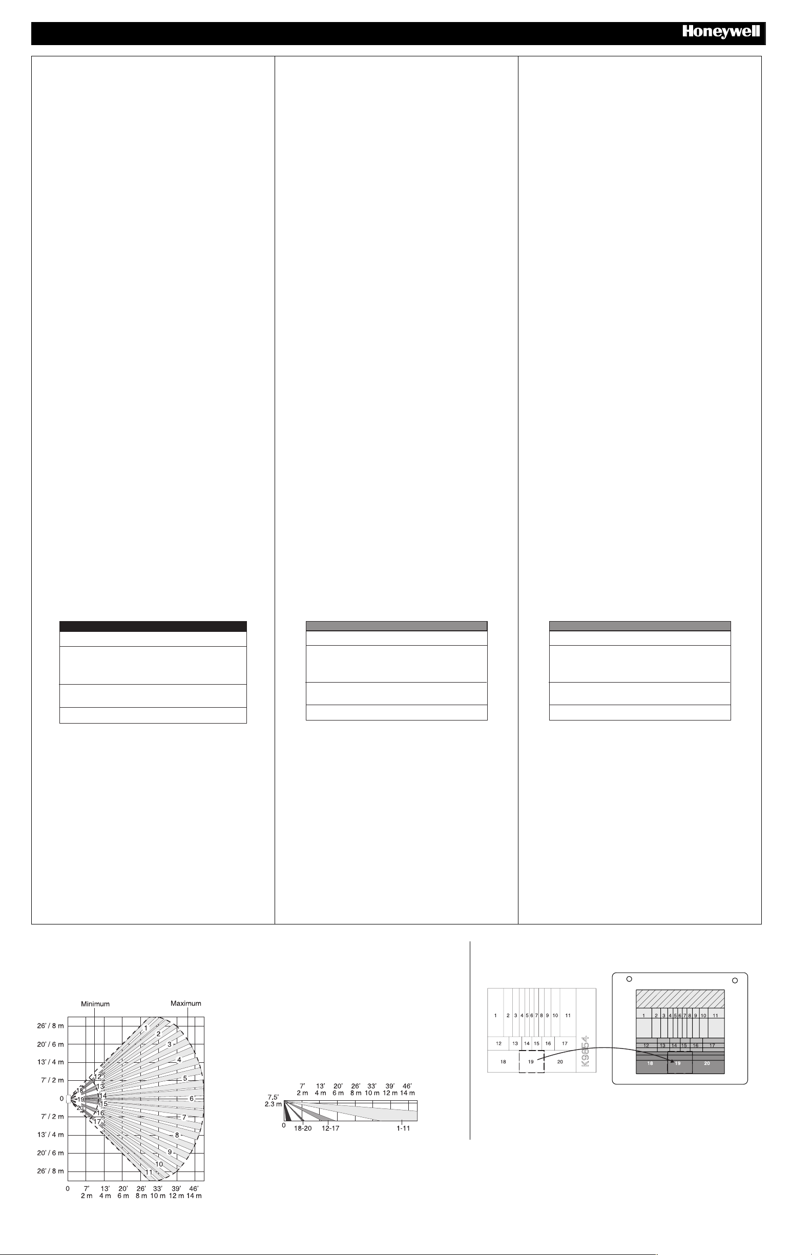
50’ / 15m Wide Angle Lens (P/N 5-532-439-01 – Installed)
Top View / VUE DE DESSUS / Vista in pianta / VISTA DESDE ARRIBA / Top View
$
$ MICROWAVE WALK TEST – 10 MINUTES
$$
1. Set the Microwave Walk Test DIP switch to ON, or toggle it ON and
OFF.
2. Set Range Adjustment potentiometer to 25% and replace the cover.
3. Walk through the detection area and observe the LED.
4. If necessary, adjust the potentiometer until desired detection range is
obtained. (For LED activati o n mea nin g, refer to t he LED Indic at or
table below.)
Indicator LEDs
Condition Indicator LED
Power Up
Normal Walk Test Red ON for 3 seconds if Alarm
Microwave Walk Test Red ON if Microwave is set too high
Trouble or Anti-Mask Fast Blinking Red (LED Enabled
Slow Blinking Red (will finish within
60 seconds)
Yellow ON for 2 seconds if Microwave
event detected
Green ON for 2 seconds if PIR event
detected
Green ON if Microwave is set correctly
OFF if Microwave is set too low
or Disabled)
%%%% ANTI-MASK
When DIP switch 5 is set to ON, the sensor indicates a mask condition
(see LED Indicator table above) when a variety of materials and
reflective objects are placed in front of it. Follow the mounting guidelines
in step 1 to avoid false mask alarms.
To clear a mask condition, visually inspect the sensor and remove any
materials blocking the sensor’s view. The sensor will clear an anti-mask
condition when three valid alarms are detected. After a mask condition
is cleared, fully walk test the required detection area.
TROUBLESHOOTING
RED LED flashing rapidly during normal operation indicates a trouble or
an anti-mask condition. If the sensor is not masked (see step 10), either
a microwave, PIR, or temperature compensation fault is present.
Solution: Momentarily power down the sensor. If the trouble does not
clear, replace the sensor. (Please ch e ck the powe r, all wiri ng an d that
the sensor is not masked before replacing the sensor.)
LENS MASKING / LENS MASKING / LENS MASKING / LENS
MASKING / LENS MASKING
TOP
25 / 35FT
5-532-489-01
Side View
VUE DE COTE / Vista in sezione / VISTA
LATERAL / Side View
- Page 2 -
Page 3
/ L
/
!
!b FOR PET IMMUNITY <SPANISH>
!!
• Mount the center of the sensor at 2.3 m (7.5 feet) high.
• Set the sensor to the Lowest or Low sensitivity (see step 6a).
• Install Pet Immune lens (5-532-489-01 - see Lens Change
Instructions on page 3).
• Install the look-down mask (see Step 6a).
• Install the sensor where pets cannot come within 1.8 m (6 ft) of the
sensor by climbing on furniture or other objects.
• Aim the sensor away from stairways, furniture or other objects that
can be climbed on by pets.
• TEST the installation site to determine the exact level of attainable
animal immunity.
Note: Pet immunity characteristics for this sensor have not been verified by
Underwriter’s Laboratories, Inc.
"
" PROGRAM SENSOR SERIAL NUMBER ID
""
Each sensor has a factory-assigned serial number which must be
entered into the control panel during the zone programming procedure.
The unique serial number can be found on a bar code label on the
sensor PCB. The serial number can be entered into the control panel in
one of the following methods:
A. Download it through software (Zone definition screen of Compass
software). This is recommended for large installations and
installations where foot traffic cannot be controlled.
B. Enter the number through the keypad at the “INPUT S/N” prompt
during manual zone programming. E n sure n o ot her pol li n g de vi ces
are activated when manually entering the sensor serial number.
C. Activate the sensor twice while at the “INPUT S/N” prompt during
manual zone programm i ng.
To enter the sensor’s serial number for option B or C:
Refer to the control panel’s manual for programming instructions.
For all V-Plex
“06” for SL (Serial Polling Device) at the “INPUT TYPE” prompt. For
Smart V-Plex
At the “INPUT S/N” prompt, either enter the seri al num b er (an d “1” for
the loop number), or fault the sensor (wave your hand in front of the
sensor or activate the tamper), the n w a it 3-6 seco nds an d faul t th e
sensor again. The keypad will beep after each fault to confirm the signal.
The sensor should now be enroll ed. If a “1” does not appear under the
“L” on the zone summary screen, press [*] and enter the loop number
manually at the next screen.
#
# NORMAL WALK TEST – 10 MINUTES
##
Normal walk test mode activates after power up mode and remains
active for 10 minutes. For an additional 10 minutes of walk test time,
remove and replace the front cover. In walk test mode, the LED is
always enabled, regardless of the LED DIP switch setting. [Note: if the
panel is not a Smart V-Plex
enabling the LED (DIP switch 3 = ON.]
Walk through the detection area and observe the LED.
If necessary, adjust the microwave range, pulse count or sensitivity
setting. (For LED activation meaning, refer to the LED Indicator table
below.)
$
$ MICROWAVE WALK TEST – 10 MINUTES
$$
1. Set the Microwave Walk Test DIP switch to ON, or toggle it ON and
OFF.
2. Set Range Adjustment potentiometer to 25% and replace the cover.
3. Walk through the detection area and observe the LED.
4. If necessary, adjust the potentiometer until desired detection range is
obtained. (For LED activati o n mea nin g, refer to t he LED Indic at or
table below.)
TM
panels, enter INT FOLLOWER 04 for the Zone Type and
TM
panels press “1” (Yes) for SMART CONTACT.
TM
panel, walk test can also be done by
Indicator LEDs
Condition Indicator LED
Power Up
Normal Walk Test Red ON for 3 seconds if Alarm
Microwave Walk Test Red ON if Microwave is set too high
Trouble or Anti-Mask Fast Blinking Red (LED Enabled
Slow Blinking Red (will finish within
60 seconds)
Yellow ON for 2 seconds if Microwave
event detected
Green ON for 2 seconds if PIR event
detected
Green ON if Microwave is set correctly
OFF if Microwave is set too low
or Disabled)
DT7500SN V-PlexTM DUAL TEC
Motion Sensor - Installation Instructions
!
!b FOR PET IMMUNITY <PORTUGUESE>
!!
• Mount the center of the sensor at 2.3 m (7.5 feet) high.
• Set the sensor to the Lowest or Low sensitivity (see step 6a).
• Install Pet Immune lens (5-532-489-01 - see Lens Change
Instructions on page 3).
• Install the look-down mask (see Step 6a).
• Install the sensor where pets cannot come within 1.8 m (6 ft) of the
sensor by climbing on furniture or other objects.
• Aim the sensor away from stairways, furniture or other objects that
can be climbed on by pets.
• TEST the installation site to determine the exact level of attainable
animal immunity.
Note: Pet immunity characteristics for this sensor have not been verified by
Underwriter’s Laboratories, Inc.
"
" PROGRAM SENSOR SERIAL NUMBER ID
""
Each sensor has a factory-assigned serial number which must be
entered into the control panel during the zone programming procedure.
The unique serial number can be found on a bar code label on the
sensor PCB. The serial number can be entered into the control panel in
one of the following methods:
A. Download it through software (Zone definition screen of Compass
software). This is recommended for large installations and
installations where foot traffic cannot be controlled.
B. Enter the number through the keypad at the “INPUT S/N” prompt
during manual zone programming. En sur e n o other polling devices
are activated when manually entering the sensor serial number.
C. Activate the sensor twice while at the “INPUT S/N” prompt during
manual zone programm i ng.
To enter the sensor’s serial number for option B or C:
Refer to the control panel’s manual for programming instructions.
For all V-Plex
“06” for SL (Serial Polling Device) at the “INPUT TYPE” prompt. For
Smart V-Plex
At the “INPUT S/N” prompt, either enter the seri al num b er (an d “1” for
the loop number), or fault the sensor (wave your hand in front of the
sensor or activate the tamper), the n w a it 3-6 seco nds an d faul t th e
sensor again. The keypad will beep after each fault to confirm the signal.
The sensor should now be enroll ed. If a “1” does not appear under the
“L” on the zone summary screen, press [*] and enter the loop number
manually at the next screen.
#
# NORMAL WALK TEST – 10 MINUTES
##
Normal walk test mode activates after power up mode and remains
active for 10 minutes. For an additional 10 minutes of walk test time,
remove and replace the front cover. In walk test mode, the LED is
always enabled, regardless of the LED DIP switch setting. [Note: if the
panel is not a Smart V-Plex
enabling the LED (DIP switch 3 = ON.]
Walk through the detection area and observe the LED.
If necessary, adjust the microwave range, pulse count or sensitivity
setting. (For LED activation meaning, refer to the LED Indicator table
below.)
$
$ MICROWAVE WALK TEST – 10 MINUTES
$$
1. Set the Microwave Walk Test DIP switch to ON, or toggle it ON and
OFF.
2. Set Range Adjustment potentiometer to 25% and replace the cover.
3. Walk through the detection area and observe the LED.
4. If necessary, adjust the potentiometer until desired detection range is
obtained. (For LED activati o n mea nin g, refer to t he LED Indic at or
table below.)
TM
panels, enter INT FOLLOWE R 04 fo r the Zo ne T ype and
TM
panels press “1” (Yes) for SMART CONTACT.
TM
panel, walk test can also be done by
Indicator LEDs
Condition Indicator LED
Power Up
Normal Walk Test Red ON for 3 seconds if Alarm
Microwave Walk Test Red ON if Microwave is set too high
Trouble or Anti-Mask Fast Blinking Red (LED Enabled
Slow Blinking Red (will finish within
60 seconds)
Yellow ON for 2 seconds if Microwave
event detected
Green ON for 2 seconds if PIR event
detected
Green ON if Microwave is set correctly
OFF if Microwave is set too low
or Disabled)
ACCESSORIES / ACCESSOIRES / ACCESSORI / ACCESORIOS /
ACCESSORIES
SMB-10
(P/N 0-000-110-01)
SMB-10C
(P/N 0-000-111-01)
SMB-10T
(P/N 0-000-155-01)
EN 50131-1 &
EN50131-2-4
NCompliant
DT7000-LRLK
15 m x 3 m
(50’ x 10’)
DT7000-HSLK
11 m x 12 m
(35’ x 40’)
DT7000-PALK
11 m x 12 m
(35’ x 40’)
LENS CHANGE INSTRUCTIONS / LENS CHANGE INSTRUCTIONS /
LENS CHANGE INSTRUCTIONS / LENS CHANGE INSTRUCTIONS /
LENS CHANGE INSTRUCTIONS
Swivel Mount Bracket
Rotule de montage
Snodo da parete
Rotula de montaje a pared
Swivel Mount Bracket
Swivel Mount Ceiling Bracket
Rotule de plafond
Snodo da soffitto
Rotula de montaje a techno
Swivel Mount Ceiling Bracket
Swivel Mount Bracket w/Tam per
Rotule de montage avec autoprotection
Snodo da parete con tamper
Rotula de montaje a pared con tamper
Swivel Mount Bracket w/Tam per
Long Range Lens Kit
Kit lentille longue portée
Kit lenti a lunga portata
Kit de lentes de largo alcance
Long Range Lens Kit
High Security Lens Kit
High Security Lens Kit
High Security Lens Kit
High Security Lens Kit
High Security Lens Kit
Pet Alley Lens Kit
Pet Alley Lens Kit
Pet Alley Lens Kit
Pet Alley Lens Kit
Pet Alley Lens Kit
%%%% ANTI-MASK
When DIP switch 5 is set to ON, the sensor indicates a mask condition
(see LED Indicator table above) when a variety of materials and
reflective objects are placed in front of it. Follow the mounting guidelines
in step 1 to avoid false mask alarms.
To clear a mask condition, visually inspect the sensor and remove any
materials blocking the sensor’s view. The sensor will clear an anti-mask
condition when three valid alarms are detected. After a mask condition
is cleared, fully walk test the required detection area.
TROUBLESHOOTING
RED LED flashing rapidly during normal operation indicates a trouble or
an anti-mask condition. If the sensor is not masked (see step 10), either
a microwave, PIR, or temperature compensation fault is present.
Solution: Momentarily power down the sensor. If the trouble does not
clear, replace the sensor. (Please ch e ck the powe r, all wiri ng an d that
the sensor is not masked before replacing the sensor.)
%%%% ANTI-MASK
When DIP switch 5 is set to ON, the sensor indicates a mask condition
(see LED Indicator table above) when a variety of materials and
reflective objects are placed in front of it. Follow the mounting guidelines
in step 1 to avoid false mask alarms.
To clear a mask condition, visually inspect the sensor and remove any
materials blocking the sensor’s view. The sensor will clear an anti-mask
condition when three valid alarms are detected. After a mask condition
is cleared, fully walk test the required detection area.
TROUBLESHOOTING
RED LED flashing rapidly during normal operation indicates a trouble or
an anti-mask condition. If the sensor is not masked (see step 10), either
a microwave, PIR, or temperature compensation fault is present.
Solution: Momentarily power down the sensor. If the trouble does not
clear, replace the sensor. (Please ch e ck the powe r, all wiri ng an d that
the sensor is not masked before replacing the sensor.)
DETECTION PATTERNS / COUVERTURE DE DETECTION / DIAGRAMMA DI COPERTURA /
PATRON DE DETECCIÓN / DETECTION PATTERNS
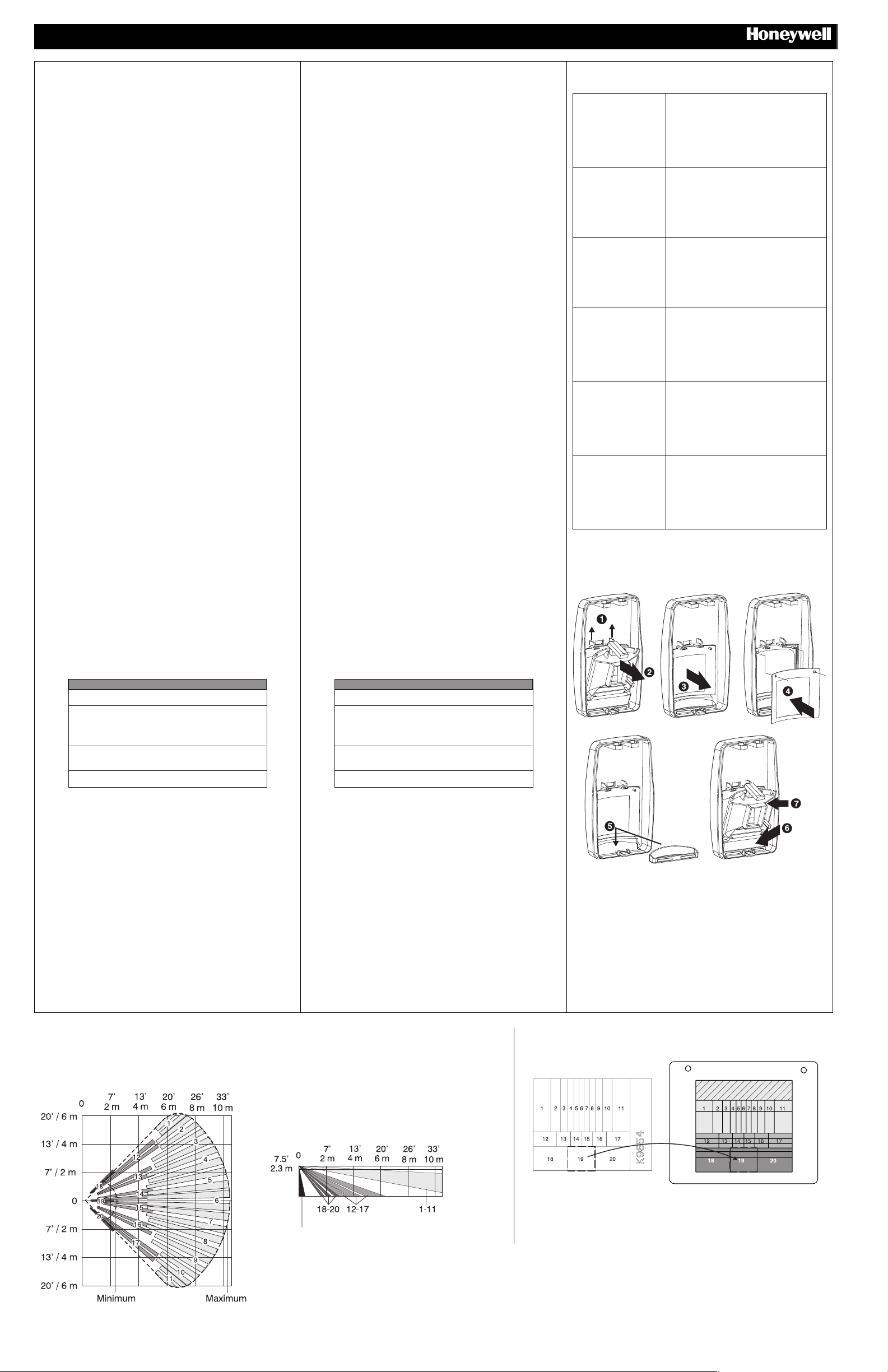
35’ / 11m Pet Immune Lens (P/N 5-532-489-01 – Included)
Top View / VUE DE DESSUS / Vista in pianta / VISTA DESDE ARRIBA / Top View
Side View
VUE DE COTE / Vista in sezione /
VISTA LATERAL / Side View
LENS MASKING
ENS MASKING / LENS MASKING / LENS
MASKING / LENS MASKING
TOP
25 / 35FT
5-532-489-01
Install Look Down Mask to block look down zones.
Install Look Down Mask to block look down zones.
Install Look Down Mask to block look down zones.
Install Look Down Mask to block look down zones.
Install Look Down Mask to block look down zones.
- Page 3 -
Page 4
DT7500SN V-PlexTM DUAL TEC
Motion Sensor - Installation Instructions
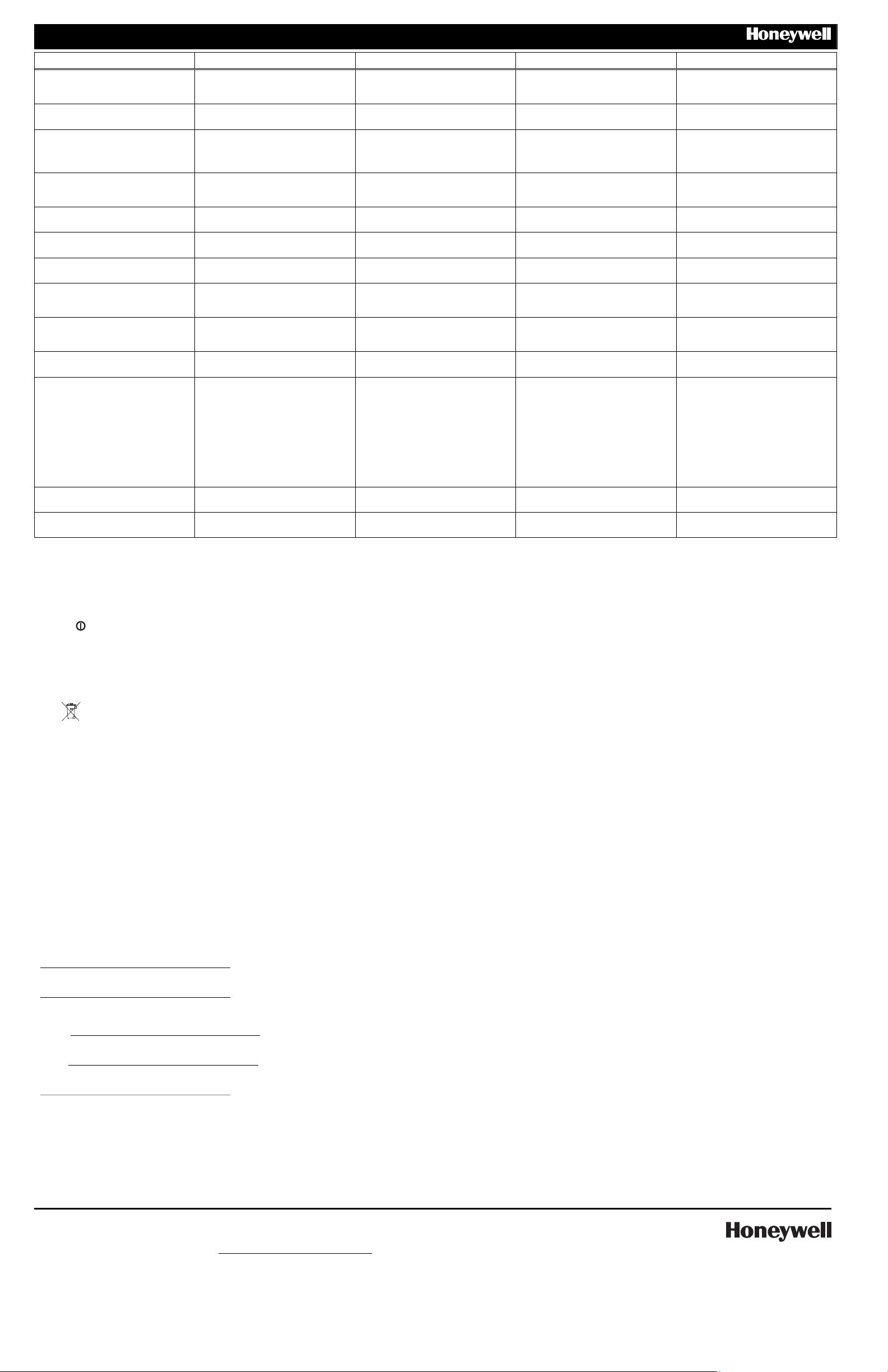
SPECIFICATIONS CARACTERISTIQUES <FRENCH> SPECIFICHE TECNICHE <ITALIAN> ESPICIFICACIONES <SPANISH> SPECIFICATIONS <PORTUGUESE>
Range: 50’ x 60’ (15 m x 18 m) [installed]
35’ x 40’ (11 m x 12 m) [included]
Portée: 15 m x 18 m [installed]
(11 m x 12 m) [included]
Portata: 50’ x 60’ (15 m x 18 m)
[installed]; 35’ x 40’ (11 m x 12 m)
Covertura: 15 m x 18 m [installed]
(11 m x 12 m) [included]
Range: 50’ x 60’ (15 m x 18 m) [installed]
35’ x 40’ (11 m x 12 m) [included]
[included]
Tamper Switch: (NC) 10 mA,
24 VDC
Power Requirements: 9 - 13 VDC @
polling loop terminals with reverse polarity
detection; nominal 11.0 VDC polling loop
Autoprotection: (NC) 10 mA,
24 VDC
Alimentation: 9 - 13 VDC @ polling loop
terminals with reverse polarity detection;
nominal 11.0 VDC polling loop
Interruttori antimanomissione: (NC) 10
mA, 24 VDC
Alimentazione: 9 - 13 VDC @ polling
loop terminals with revers e polarity
detection; nominal 11.0 VDC polling loop
Salida de tamper: (NC) 10 mA,
24 VDC
Requerimientos de alimentación: 9 - 13
VDC @ polling loop terminals with reverse
polarity detection; nomin al 11. 0 VDC
Tamper Switch: (NC) 10 mA,
24 VDC
Power Requirements: 9 - 13 VDC @
polling loop terminals with reverse polarity
detection; nominal 11.0 VDC polling loop
polling loop
Current: 3.0 mA nominal (with LED
disabled); 6.0 mA nominal (with LE D
enabled); 6.5 mA max. (during warm up)
Frequency: 24.125 GHz (K-band) Hyperfréquence: 24.125 GHz
PIR White Light Immunity: 6,500 Lux
typical
Fluorescent Lig ht Fil t er : 50 Hz or 60
Hz, auto-detection
Operating Temperature: -4° to 131° F
(-20° to 55° C), 5% - 95% relative humidity
(non-condensing)
Self-Tests:
Microwave supervision; End-to-End PIR
self-test; Temperature Compensation
Temperature Compensation: Advanced
Dual Slope
PIR Fields of View:
Wide Angle Lens (P/N 5-532-439-00)
44 long range zones
12 intermediate zones
6 lower zones
4 look-down zones
Pet Immune Lens (P/N 5-532-489-00)
44 long range zones
36 intermediate zones
18 lower zones
4 look-down zones
Dimensions: 4.93” x 2.93” x 1.68”
(12.5cm x 7.5cm x 4.3cm)
Weight: 149.0 g (5.26 oz)
Packaged: 205.0 g (7.23 oz)
Current: 2.5 mA nominal (with LED
disabled; 5.0 mA nominal (with LED
enabled
(K-band)
Immunity à la lumière blanche: 6,500
Lux Typique
Filtre lumière Fluorescente: 50 Hz or 60
Hz, sélectionnable
Température de fonctionnement:
-20° à 55° C; Humidité relative: 5% à 95%
sans condensation
Auto-Tests:
Supervision hyperfréquences; IRP;
Compensation en température
Compensation en tem pérature: A
double pente
Champ de détection IRP:
Grand Angle Lens ( P/N 5-532-439 -00)
44 faisceaux longs
12 intermediaires
6 courts
4 verticaux
Pet Immune Lens ( P/N 5-532-48 9-00 )
44 faisceaux longs
36 intermediaires
18 courts
4 verticaux
Dimensions:
12.5cm x 7.5cm x 4.3cm
Masse: 149.0 g
Emballé: 205.0 g
Current: 2.5 mA nominal (with LED
disabled; 5.0 mA nominal (with LED
enabled
Frequenza microonda: 24.125 GHz (Kband)
Immunita PIR alla luce bianca: 6,500
Lux tipica
Filtro luce Fluorescente: 50Hz o 60Hz,
selezionabile
Temperatura di esercizio: da -20° a 55°
C; 5% - 95% umidità relative (non condensansante)
Auto-Tests:
Supervisione Microonda; Auto-test PIR;
Comp. Temperatura
Compensazione Temperatura:
Avanzata a doppio gradiente
Zone PIR:
Wide Angle Lens (P/N 5-532-439-00)
44 lunga portata
12 intermedie
6 inferiori
4 antistrisciamento
Pet Immune Lens (P/N 5-532-489-00)
44 lang bereik zones
36 midden
18 laag
4 kruipzones
Dimensioni:
12.5cm x 7.5cm x 4.3cm
Peso: 149.0 g
Impachettato: 205.0 g
Current: 2.5 mA nominal (with LED
disabled; 5.0 mA nominal (with LED
enabled
Frecuencias Microondas: 24.125 GHz
(K-band)
Immunidad contr a luc es blancas: 6,500
Lux typical
Filtro Luz Fluorescente: 50 Hz or 60 Hz,
selectable
Temperatura de funcionamiento: -4° to
131° F (-20° to 55° C); Humedad relativa:
5% to 95% sin condensación
Auto-Test:
Supervisión Microondas; Test PIR; Comp.
Temp.
Compensación de temperatura: Doble
pendiente avanzada
Zonas de detección:
Wide Angle Lens (P/N 5-532-439-00)
44 zonas de largo alcance
12 zonas intermedias
6 zonas de corto alcance
4 zonas de angulo cero
Pet Immune Lens (P/N 5-532-489-00)
44 lang bereik zones
36 midden
18 laag
4 kruipzones
Dimensiones:
12.5cm x 7.5cm x 4.3cm
Peso: 149.0 g
Embalaje del producto: 205.0 g
Current: 3.0 mA nominal (with LED
disabled); 6.0 mA nominal (with LE D
enabled); 6.5 mA max. (during warm up)
Frequency: 24.125 GHz (K-band)
PIR White Light Immunity: 6,500 Lux
typical
Fluorescent Lig ht Fil t er : 50 Hz or 60
Hz, auto-detection
Operating Temperature: -4° to 131° F
(-20° to 55° C), 5% - 95% relative humidity
(non-condensing)
Self-Tests:
Microwave supervision; End-to-End PIR
self-test; Temperature Compensation
Temperature Compensation: Advanced
Dual Slope
PIR Fields of View:
Wide Angle Lens (P/N 5-532-439-00)
44 long range zones
12 intermediate zones
6 lower zones
4 look-down zones
Pet Immune Lens (P/N 5-532-489-00)
44 long range zones
36 intermediate zones
18 lower zones
4 look-down zones
Dimensions: 4.93” x 2.93” x 1.68”
(12.5cm x 7.5cm x 4.3cm)
Weight: 149.0 g (5.26 oz)
Packaged: 205.0 g (7.23 oz)
APPROVAL LISTINGS / AGREMENT / OMOLOGAZIONI / HOMOLOGACIONES / APPROVAL LISTINGS
• FCC part 15, Class B verified
• IC, RSS-210, Class B verified
• CE
, C-Tick, cULus Listed, INCERT, IMQ
• EN 50131-1 and EN 50131-2-4 Security Grade 2, Environment Class II.
• EN 50131-1 en EN 50131-2-4 Security Grade 2; Environmental Class II.
• EN 50131-1 et EN 50131-2-4, grade 2, classe enironnementale II.
• EN 50131-1 e EN 50131-2-4 Grado di Sicurezza 2; Classe Ambientale II.
• EN50131-1 y EN 50131-2-4 Grado de Seguridad 2, Clase ambiental II.
NOTES DE CONFORMITÉ
• En référentiel TS 50131-2-4, install ation à 2.30 m, choisir la sensibilité haute, et mettre en place la vis
de capot (fournie)..
• Compatible pour un raccordem e nt à une alimentation régulée EN 60950 Classe II.
NOTE DI CONFORMITA’
• Per installazioni TS 50131-2-4, montare il sensore a 2.3 m, impostare il sensore in alta sicurezza e
bloccare il coperchio con una vite (Inclusa).
• Per connessioni con alimentatori compatibili EN 60950 Classe II in contesto EU.
NOTAS DE CONFORMIDAD
•
COMPLIANCE NOTES
• For EN 50131-2-4 compliant installations, mount sensor at 2.3m (7.5ft), set pulse count to 1, set sensitivity to
• Suitable for connection to an EN60950 Class II Limited Power Source in European installations.
UL COMPLIANCE NOTES
• Product must be tested once each year.
• Wiring the terminals incorrectly may damage this unit, and/or the equipment wired to it.
High, and install cover screw.
• Para instalaciones que cumplen TS50131-2-4: monte el detector a una altura de 2.3m (7’6”),
seleccione alta sensibilidad y coloque el tornillo de la tapa.
• Adecuado para conectarlo con una fuente de alimentación EN60950 Clase II en instalaciones
Europeas.
COMPLIANCE NOTES <PORTUGUESE>
• For EN 50131-2-4 compliant installations, mount sensor at 2.3m (7.5ft), set pulse count to 1, set
sensitivity to High, and install cover screw.
• Suitable for connection to an EN60950 Class II Limited Power Source in European installations.
To obtain applicable EU compliance Declaration of Conformities for this product, please refer to our Website,
http://www.security.honeywell.com/hsce/international/index.html. For any additional information regarding the compliance of this
product to any EU specific requirements, please contact:
Les déclarations de conformité aux normes Européennes de ce produit sont disponibles sur notre site Internet à l’adresse
http://www.security.honeywell.com/hsce/international/index.html. Toutes informations complémentaires relatives à la conformité
de ce produit à des normes Européennes particulières peuvent être obtenues auprès de notre département «Assurance
Qualité»:
Per ottenere una copia della Dichiarazione di conformità CE applicabile di questo prodotto, si prega di fare riferimento al nostro
sito Web, http://www.security.honeywell.com/hsce/international/index .html. Per ogni ulteriore informazione relativa alla
conformità di questo prodotto alle normative specifiche CE, siete pregati di contattare:
Para obtener la conformidad con la normativa EU y declaración de conformidad de este producto, por favor visite nuestra
Website, http://www.security.honeywell.com/hsce/international/index.html. Para cualquier información adicional sobre este
producto u otras especificaciones EU, por favor contacte con:
<PT> To obtain applicable compliance Declaration of Conformities for this product, please refer to our Website,
http://www.security.honeywell.com/hsce/international/index.html. For any additional information regarding the compliance of this
product to any EU specific requirements, please contact:
Quality Assurance Department,
Honeywell Security & Custom Electronics,
Newhouse Industrial Estate
Motherwell,
Lanarkshire ML1 5SB,
Scotland, United Kingdom.
Tel: +44(0)1698 738200
Email: [email protected]
FCC NOTICE:
This equipment has been tested and found to comply with the limits for a Class B digital device, pursuant to Part 15 of the FCC Rules.
These limits are designed to provide reasonable protection against harmful interference in a residential installation. This equipment
generates, uses and can radiate radio frequency energy and, if not installed and used in accordance with the instructions, may cause
harmful interference to radio communications. However, there is no guarantee that interference will not occur in a particular installation.
If this equipment does cause harmful interference to radio or television reception, which can be determined by turning the equipment off
and on, the user is encouraged to try to correct the interference by one or more of the following measures:
− Reorient or relocate the receiving antenna.
− Increase the separation between the equipment and receiver.
− Connect the equipment into an outlet on a circuit different from that to which the receiver is connected.
− Consult the dealer or an experienced radio/television technician for help.
The user is cautioned that changes or modifications not expressly approved by Honeywell could void the user’s authority to
operate this equipment.
IC NOTICE:
This Class B digital device complies with RSS-210 of the IC Rules. Operation is subject to the following two
conditions: (1) this device may not cause harmful interference, and (2) this device must accept any interference
received, including interference that may cause undesired operation.
Cet appareil numérique de la Classe B est conforme à la norme CNR-210 des règles d’IC. L'utilisation de ce dispositif est
autorisée seulement aux deux conditions suivantes : (1) il ne doit pas produire de brouillage, et (2) l'utilisateur du dispositif doit
être prêt à accepter tout brouillage radioélectrique reçu, même si ce brouillage est susceptible de compromettre le
fonctionnement du dispositif.
2007 Honeywell International Inc. Honeywell, IntelliSense and DUAL TEC are registered trademarks of Honeywell International Inc.
All other trademarks are the properties of their respective owners. All rights reserved. Made in China.
For the latest U.S. warranty information, please go to: www.honeywell.com/security/hsc/resources/wa or
Please contact your local aut horised Honeywell representative for product warranty information.
Contacter un r evendeur Hon eywell autorisé pour obtenir des informations sur la garantie de ce produit.
Contatti il suo rappresentante Honeywell per ulteriori informazioni su prodotti e garanzia.
P/N P800-01643 Rev A
Por favor cont acte con su dist ribuidor Honeywell Security para informac ión sobre la garantía del pro ducto.
<PT> Please c ontact your local authorised Honeywell r epresentative for product warranty information.
- Page 4 -
 Loading...