

Page 1
DS05C,D,G
DIAL-SET® PRESSURE REGULATING VALVES
FEATURES
• Built-in, factory calibrated outlet pressure adjustment
dial.
• Noncorroding unitized cartridge contains all working
parts and is easily replaceable.
• Includes built-in strainer and thermal bypass.
• Balanced seat construction provides superior
pressure regulation.
• Inlet and outlet are internally threaded female NPT, and
externally threaded for use with union assemblies.
• Stand-In Pipe available for temporary installation
during construction or system flushing.
PRODUCT DATA
APPLICATION
The Honeywell DS05C,D,G Dial-Set® Pressure Regulating
Valve is a high quality pressure regulating valve that maintains
a constant outlet pressure over a wide range of inlet supply
pressures. It is suitable for potable water and irrigation
applications. The downstream pressure adjustment dial
eliminates the need for a pressure gauge when adjusting the
pressure setting (static pressure only).
SPECIFICATIONS
Model: DS05 Dial-Set Pressure Regulating Valves.
Construction Materials:
Body: Bronze.
Internal Parts: Stainless steel and engineered plastics.
Regulator Mechanism: Fabric-reinforced diaphragm.
Seat Design: Balanced single seat construction.
Inlet Pressure (Maximum): 400 psi maximum.
Reduced Pressure Range:
5 to 75 psi (1/2 in. to 1 in.).
15 to 130 psi (1-1/4 in.).
Outlet Pressure: Factory set at 60 psi.
Dial Calibration: ±4 psi.
Contents
Applications/Features/Specifications.................................1
Ordering Information .........................................................2
Installation/Maintenance....................................................4
Troubleshooting.................................................................6
Operation...........................................................................7
DS05 Parts and Accessories.............................................8
62-3041—4
Page 2
DS05C,D,G
Differential: 14 psi minimum (inlet to outlet).
Reduced Ratio: 10:1 maximum.
Temperature (Maximum):
Air: 158° F (70° C).
Water: 180° F (82° C).
Ambient Temperature Range:
33° F to 140° F (1° C to 60° C).
Pipe Sizes Available:
1/2 in., 3/4 in., 1 in., and 1-1/4 in. available.
Connections:
Can be configured as female thread-by-thread, single-union
or double-union, NPT threaded or sweat.
Strainer Screen Size: 0.032 in. (0.8 mm).
Gauge Tap: 1 1/4 in. model only.
Approvals:
ASSE (Std. 1003) Certified.
IAPMO, CSA, and City of L.A Listed.
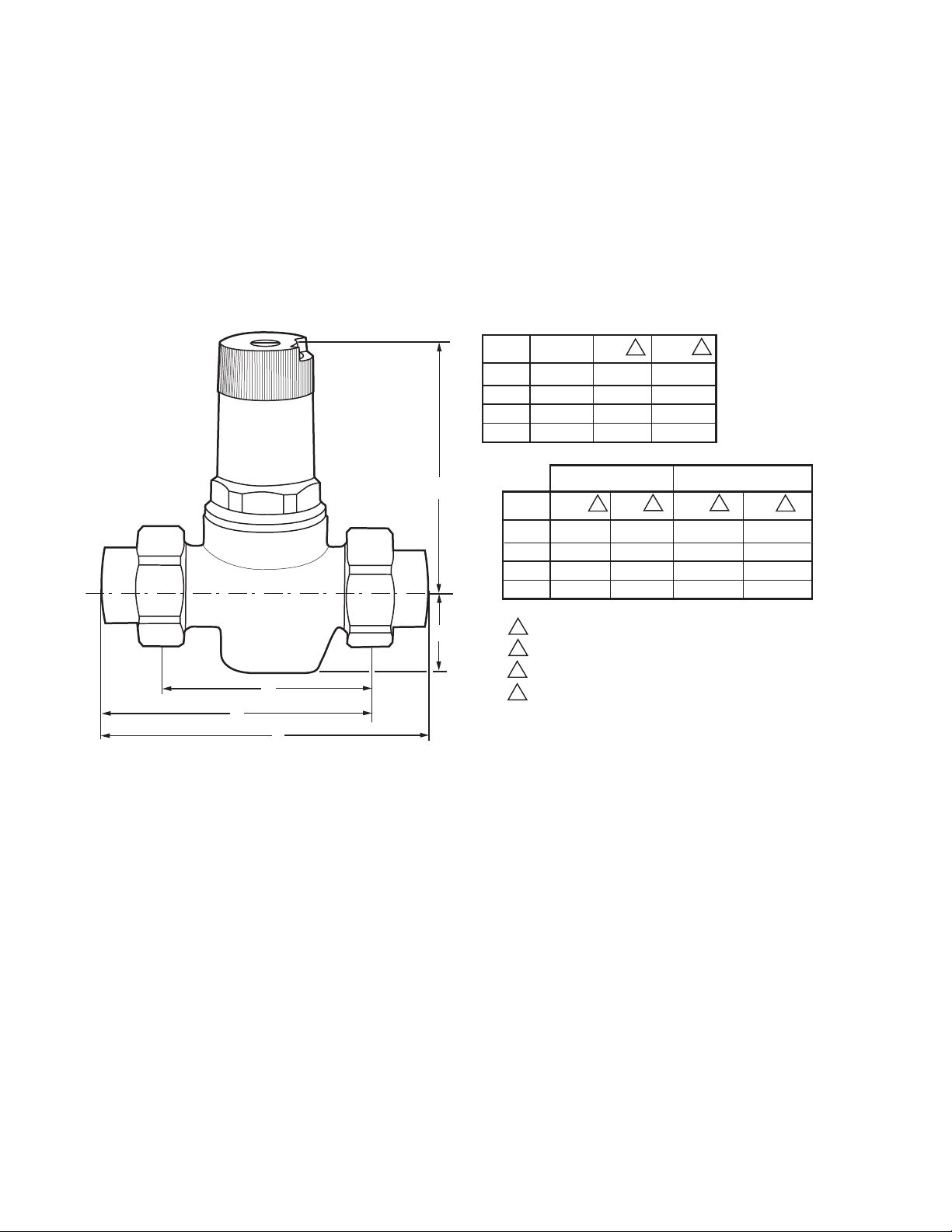
Dimensions: See Figure 1.
SIZE
(INCHES)
1/2
3/4
1
1-1/4
C
(INCHES)
4
4
4
5-9/16
SIZE
1/2
3/4
1
1-1/4
C
(102)
(102)
(102)
(141)
SWEAT TAILPIECE
A
3-7/8
4-5/16
(110)
5-1/4
(133)
6-3/16
(157)
(99)
2
1-3/4
1-3/4
1-3/4
2-5/8
D
(32)
(32)
(32)
(66)
B
4-5/8
5-3/16
6-1/2
7-11/16
4
3
(118)
(132)
(166)
(195)
1
E
(81)
3-3/16
(89)
3-1/2
(100)
3-15/16
(119)
4-11/16
THREADED TAILPIECE
2
AB
(103)
4-1/16
(110)
4-5/16
(127)
5
(152)
6
4-15/16
5-3/16
6-1/16
7-5/16
3
(126)
(132)
(154)
(185)
D
E
A
1 NON-UNION MODEL CONFIGURATION.
2 SINGLE-UNION MODEL CONFIGURATION.
3 DOUBLE-UNION MODEL CONFIGURATION.
4 DIMENSION WITH GAUGE PLUG.
M13748
B
Fig. 1. DS05 Installation dimensions in inches (mm).
ORDERING INFORMATION
When purchasing replacement and modernization products from your TRADELINE® wholesaler or distributor, refer to the
TRADELINE
If you have additional questions, need further information, or would like to comment on our products or services, please write or
phone:
1. Your local Honeywell Automation and Control Products Sales Office (check white pages of your phone directory).
2. Honeywell Customer Care
In Canada—Honeywell Limited/Honeywell Limitée, 35 Dynamic Drive, Toronto, Ontario M1V 4Z9.
International Sales and Service Offices in all principal cities of the world. Manufacturing in Australia, Canada, Finland, France,
Germany, Japan, Mexico, Netherlands, Spain, Taiwan, United Kingdom, U.S.A.
®
Catalog or price sheets for complete ordering number.
1885 Douglas Drive North
Golden Valley, Minnesota 55422-4386
62-3041—4 2
Page 3
DS05C,D,G
Water Capacities (See Table 1)
The suitability of a given regulator size is dependent on the
pressure requirements where it will operate. For the pressure
regulator valve size required for a specific installation,
determine the following:
1. Pressure differential between inlet and outlet pressure in
pounds per square inch (psi),
2. Capacity in gallons per minute, and
3. Allowable reduced pressure falloff in psi.
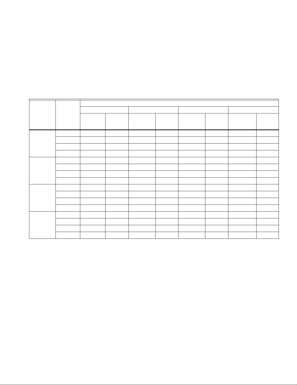
Table 1. Water Capacities.
Pressure Differential Between Inlet and Outlet
25 psi 50 psi 75 psi 100 psi or more
Flow
Velocity
(ft/sec)
a
Flow
Capacity
(US gpm)
Pressure
Regulator
Valve Size
Reduced
Pressure
Falloff
(psi)
Capacity
(US gpm)
1/2 inch 6 1.2 1.3 2.3 2.4 3.3 3.5 4.4 4.6
10 8.8 9.3 10.1 10.7 10.6 11.2 10.6 11.2
15 13.2 13.9 15.0 15.8 17.6 18.6 17.6 18.6
20 17.6 18.6 20.7 21.9 22.0 23.2 22.9 24.2
3/4 inch 6 3.6 2.1 4.0 2.4 4.0 2.4 4.0 2.4
10 8.1 4.9 9.3 5.6 9.9 6.0 9.9 6.0
15 14.7 8.8 17.6 10.6 19.8 11.9 20.6 12.4
20 23.0 13.8 27.7 16.7 32.1 19.3 4.1 20.5
1 inch 6 5.7 2.1 5.9 2.2 5.9 2.2 6.3 2.4
10 13.2 4.9 15.4 5.7 15.7 5.8 16.4 6.1
15 19.6 7.3 24.6 9.1 18.6 10.6 31.7 10.8
20 25.7 9.6 32.1 11.9 37.6 14.0 43.6 16.2
1-1/4 inch 6 13.5 2.6 16.0 3.4 20.0 4.3 22.0 4.7
10 22.0 4.7 29.0 6.2 34.0 7.3 38.0 8.1
15 37.0 7.9 56.0 12.0 62.5 13.4 73.0 15.6
20 55.0 11.8 78.0 16.7 87.0 18.6 101.0 21.6
a
Velocity in feet per second is based on schedule 40 pipe size. Recommended pressure falloff for general use is approximately
104 kPa (15 psi). Recommended velocities for the flow of water: residential and general use, 5 to 10 ft/sec; industrial use, 7 to 15
ft/sec; boiler feed, 7 to 15 ft/sec.
Given these variables, use Table 1 to determine the proper
size pressure regulator valve for your application.
Example: An installation has 135 psi inlet pressure, 60 psi
outlet pressure (75 psi pressure differential). If a 12 gpm
capacity is required with only 10 psi falloff allowable, a 1/2 in.
DS05 is required.
Velocity
(ft/sec)
a
Flow
Capacity
(US gpm)
Vel ocit y
(ft/sec)
a
Flow
Capacity
(US gpm)
Vel ocit y
(ft/sec)
a
3 62-3041—4
Page 4

DS05C,D,G
A
INSTALLATION
When Installing this Product...
1. Read these instructions carefully. Failure to follow them
could damage the product or cause a hazardous
condition
2. Check the ratings given in these instructions and on the
product to make sure the product is suitable for your
application.
3. Installer must be a trained, experienced service
technician.
4. After installation is complete, check out the product
operation as provided in the instructions.
Procedure
1. Flush the system clear of sediment or debris.
2. Close the supply valve and downstream isolating valve
(if one is installed).
3. Install the DS05 with the arrow on the body pointing in
the direction of water flow. (The DS05 can be mounted in
any position.)
The DS05 can be installed directly onto the pipe by using the
female NPT threads on each end. If space limitations restrict
turning the DS05, install single-unions or double-unions.
NOTE: Heat from soldering can damage internal parts of the
DS05. Always solder the tailpieces separately from
the DS05.
4. Open the supply valve slowly and check for leakage and
proper operation of the DS05.
Changing the Downstream Pressure (See Fig. 2)
Remove the dust cap from the DS05. The DS05 is factory set
to 60 psi.
MAINTENANCE
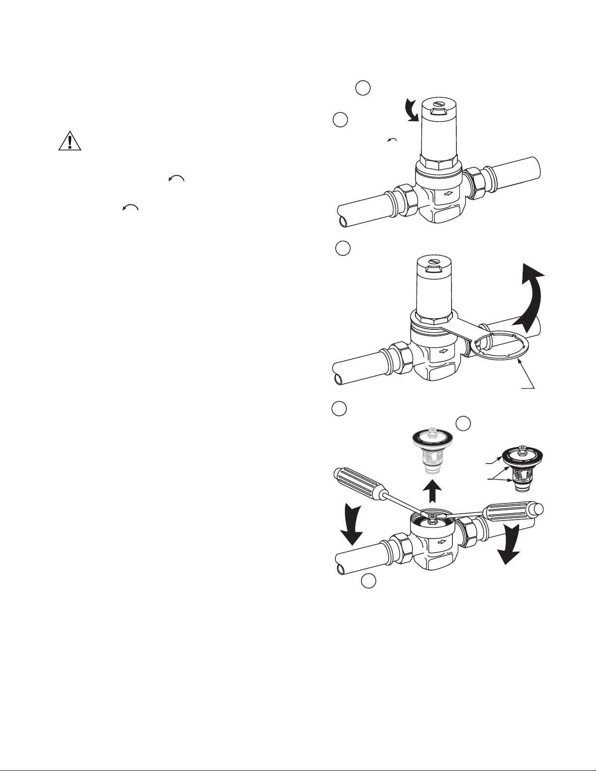
Replacing the Cartridge (See Fig. 3)
The working parts of the DS05 including diaphragm, valve
seat, strainer and disk are all contained in a replaceable
cartridge. To replace the cartridge:
1. Shut off the supply valve and open a downstream faucet
to relieve the system pressure.
2. Loosen the setpoint screw by turning it counterclockwise (Do not remove this screw).
LOOSEN LOCKING
SCREW ONE TURN
DJUST SETPOINT AT THE DESIRED VALUE BY ACTUATING SELECTOR.
60
INLET PRESSURE (MAXIMUM): 400 PSI
REDUCED PRESSURE RANGE:
15 TO 75 PSI 1/2 IN. –1 IN. SIZE
15 TO 130 PSI 1 1/4 IN. SIZE
NOTE: DO NOT DISMANTLE KNOB
SET-POINT READOUT HAS BEEN CALIBRATED
IN THE FACTORY AND SET AT 60 PSI.
DISMANTLING THE SELECTOR KNOB WILL
CANCEL THIS CALIBRATION. RECALIBRATE
USING A PRESSURE GAUGE. SEE RECALIBRATION.
Fig. 2. Changing outlet pressure.
60
M7315C
To adjust the outlet pressure to a desired setting:
1. Loosen the locking screw by turning one turn counterclockwise (do not remove this screw).
2. Turn the adjusting knob counter-clockwise
to reduce pressure or clockwise to increase
pressure.
3. Lock the setting by turning the locking screw
clockwise .
4. Replace the dust cap over the dial.
CAUTION
To prevent injury and/or equipment damage,
loosen locking screw and turn adjusting knob
counter-clockwise to remove spring tension.
3. Turn adjusting knob counter-clockwise to remove
spring tension.
4. Remove the bonnet and washer using an MT06A
Service Tool.
5. Remove the cartridge using two screwdrivers as levers.
Attach new O-rings and screen onto the new cartridge.
6. Make sure O-rings are properly installed above and
below the screen.
7. Insert the new cartridges. Do not scratch the sides.
8. Place the washer on top of the cartridge.
NOTE: The inner lip must be pointing up to avoid damaging
the diaphragm.
9. Replace the spring and bonnet.
10. Readjust the outlet pressure to the desired setting by
using the procedure described in Changing the
Downstream Pressure section.
62-3041—4 4
Page 5
Cleaning the Cartridge Screen
To clean the cartridge screen:
1. Shut off the supply valve and open a downstream faucet
to relieve the system pressure.
CAUTION
To prevent injury and/or equipment damage,
loosen locking screw and turn adjusting knob
counter-clockwise to remove spring tension.
Do not remove screw.
2. Loosen locking screw and turn adjusting knob counter-
clockwise to remove spring tension.
3. Remove the bonnet and washer using an MT06A service
tool.
4. Remove the cartridge using two screwdrivers as levers
as shown in Figure 3.
5. Remove and clean the cartridge screen.
6. Replace the cartridge screen and make sure the O-rings
are installed properly.
7. Carefully clean the cartridge seat area.
8. Insert the cartridge. Do not scratch the sides.
9. Place the washer on top of the cartridge.
LOOSEN THE SETPOINT DIAL LOCKING SCREW.
1
UNSTRESS THE
2
PRESSURE SPRING
BY TURNING COUNTERCLOCKWISE .
UNSCREW THE BONNET WITH MT06A SERVICE TOOL.
3
60
60
DS05C,D,G
NOTE: The inner lip must be pointing up to avoid damaging
the diaphragm.
10. Replace the spring and bonnet.
11. Readjust the outlet pressure to the desired setting by
using the procedure described in Changing the Outlet
Pressure section.
Recalibration
If the dial knob assembly has been dismantled, recalibration is
necessary. Recalibrate as follows:
1. Install a good quality pressure gauge at the gauge tap
connection.
2. Open supply pressure and adjust spindle until the gauge
shows 60 psi.
3. Reassemble dial ring and adjustment knob so dial reads
60 psi.
MT06A SERVICE TOOL
(ORDER SEPARATELY)
REMOVE CARTRIDGE USING TWO SCREWDRIVERS AS LEVERS.
4
WHEN REASSEMBLING,
5
ENSURE O-RINGS AND
WASHER ARE PROPERLY
INSTALLED
WASHER
(LIP UP)
O-RINGS
REASSEMBLE BONNET IN REVERSE ORDER.
6
M7313A
Fig. 3. Replacing the DS05 cartridge.
5 62-3041—4
Page 6

DS05C,D,G
TROUBLESHOOTING
Table 2 provides a troubleshooting guide for the DS05 Dial Pressure Regulating Valve.
Table 2. Troubleshooting the DS05 Dial-Set Pressure Regulating Valve.
Problem Solution
Whistling noise. • Slightly increase or decrease the outlet pressure until the noise goes away.
Will not hold pressure. • Clean the filter cartridge as described in the installation section.
Chatters. • Replace screen and O-rings.
• Replace the cartridge as shown in Figure 3.
Freezes up. • Replace bonnet or cartridge if damaged.
• To avoid further freeze up:
— Temporarily (slightly) open a downstream faucet if the DS05 will be exposed to
temperatures below 32° F (0° C). The slight water flow will eliminate freeze-up.
— Move the DS05 to a location with an ambient temperature above 32° F (0° C) if it is
currently exposed to prolonged temperature below 32° F (0° C).
Pressure gauge measures a lower
pressure under flow conditions than was
originally set during static conditions.
• DS05 is functioning properly. No action is necessary. The pressure decrease is
characteristic of all direct acting pressure regulating valves and is referred to as
falloff.
62-3041—4 6
Page 7

DS05C,D,G
OPERATION
DUST CAP
(BLACK)
LOCKING SCREW
ADJUSTING
KNOB
60
DIAL RING
BONNET
SPINDLE
SPRING
The Honeywell DS05 Dial-Set Pressure Regulating Valve is a
balanced, direct acting pressure regulating valve. The DS05
provides constant downstream pressure regardless of varying
inlet pressures and downstream flow demands.
The spring force holds the valve in the open position until
downstream pressure sensed by a port, is sufficient to press
on the underside of the diaphragm and close the valve. As
downstream pressure drops due to demand, the force on the
diaphragm is reduced and the valve opens. Adjustment is
made by manually turning the adjustment knob
clockwise to increase the spring force and require a
higher downstream pressure to close the valve. Similarly,
reducing the spring force lowers the outlet set pressure. A
factory-calibrated dial is built into the adjustment mechanism to
allow outlet pressure (no flow) to be set without a gauge. A
locking screw maintains the setting. A black plastic cover is
provided to conceal the setting and protect the Dial-Set from
moisture and debris.
Once the outlet pressure is set, the DS05 automatically
regulates to maintain the downstream pressure. See Figure 5
for the internal construction of the DS05.
Minimum ambient rating is 33° F (1° C).
GASKET
TAILPIECE
NUT
GAUGE TAP PLUG
WASHER
CARTRIDGE
O-RING
SCREEN
O-RING
GASKET
BODY
Fig. 4. DS05 exploded view.
NUT
TAILPIECE
M7314
INLET
60
OUTLET
M7327
Fig. 5. Internal construction of DS05.
7 62-3041—4
Page 8
DS05C,D,G
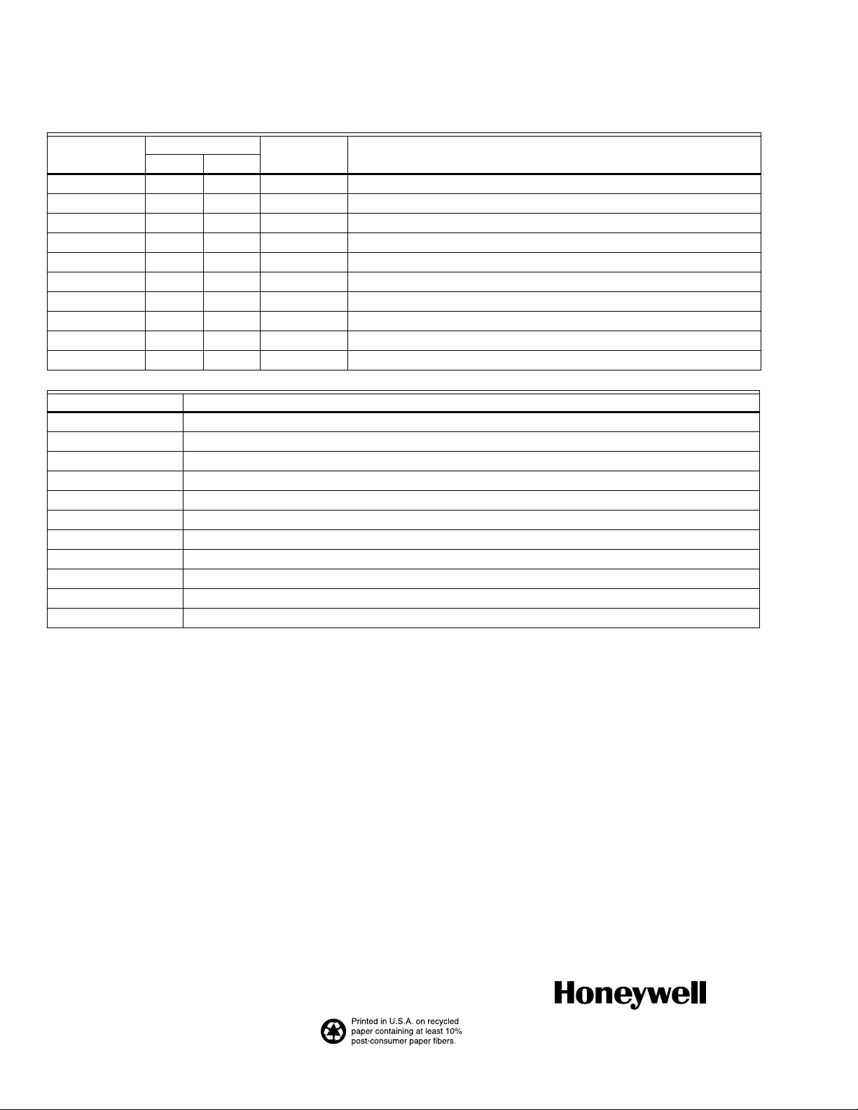
DS05 Parts & Accessories
Product
Number
Pipe Size
Pipe
Connection Description(inch) DN
K06U1135 1-1/4 DN32 - Union kit for 1-1/4 in. NPT D05 and DS05 Series Valves.
K06U1150 3/4 DN20 Sweat 3/4 in. Jumper Kit- 2 Sweat Unions, Gaskets and Nuts.
K06U1168 1 DN25 Sweat 1 in. PRV Jumper Kit- 2 Sweat Unions, Gaskets and Nuts.
K06U1184 3/4 DN20 Female NPT 3/4 in. PRV Jumper Kit- 2 Threaded Unions, Gaskets and Nuts.
K06U1192 1 DN25 Female NPT 1 in. PRV Jumper Kit- 2 Threaded Unions, Gaskets and Nuts.
K06U1200 1-1/4 DN32 Sweat 1-1/4 in. Jumper Kit - 2 Sweat Unions, Gaskets, and Stand-in Pipe.
K06U1218 1-1/4 DN32 Female NPT 1-1/4 in. Jumper Kit- 2 Threaded Unions, Gaskets and Stand-in Pipe.
PRV202-039 3/4 DN20 Male NPT 3/4 in. Stand-in Pipe.
PRV202-040 1 DN25 Male NPT 1 in. PRV Stand-in Pipe.
PRV203-034 1-1/4 DN32 Male NPT 1-1/4 in. PRV Stand-in Pipe.
Product Number Description
272838 Bonnet for 1/2 in. and 3/4 in.
272839 Bonnet for 1 in. and 1-1/4 in.
272840 Union Gaskets for 1/2 in.
272841 Union Gaskets for 3/4 in.
272842 Union Gasket for 1 in.
272843 Union Gasket for 1-1/4 in.
K05A1009 Repair Kit for 1/2 and 3/4 in.
K05A1017 Repair Kit for 1 and 1-1/4 in. (DS05C)
K05A1025 Repair Kit for DS05C/D05T 1/2 in, 3/4 in. & 1 in.
K05B1007 Repair Kit for 1/2 in. and 3/4 in.
K05B1015 Repair Kit for 1 in.
Automation and Control Solutions
Honeywell International Inc. Honeywell Limited-Honeywell Limitée
1985 Douglas Drive North 35 Dynamic Drive
Golden Valley, MN 55422 Toronto, Ontario M1V 4Z9
customer.honeywell.com
® U.S. Registered Trademark
© 2006 Honeywell International Inc.
62-3041—4 C.H. Rev. 10-06
 Loading...