

Page 1
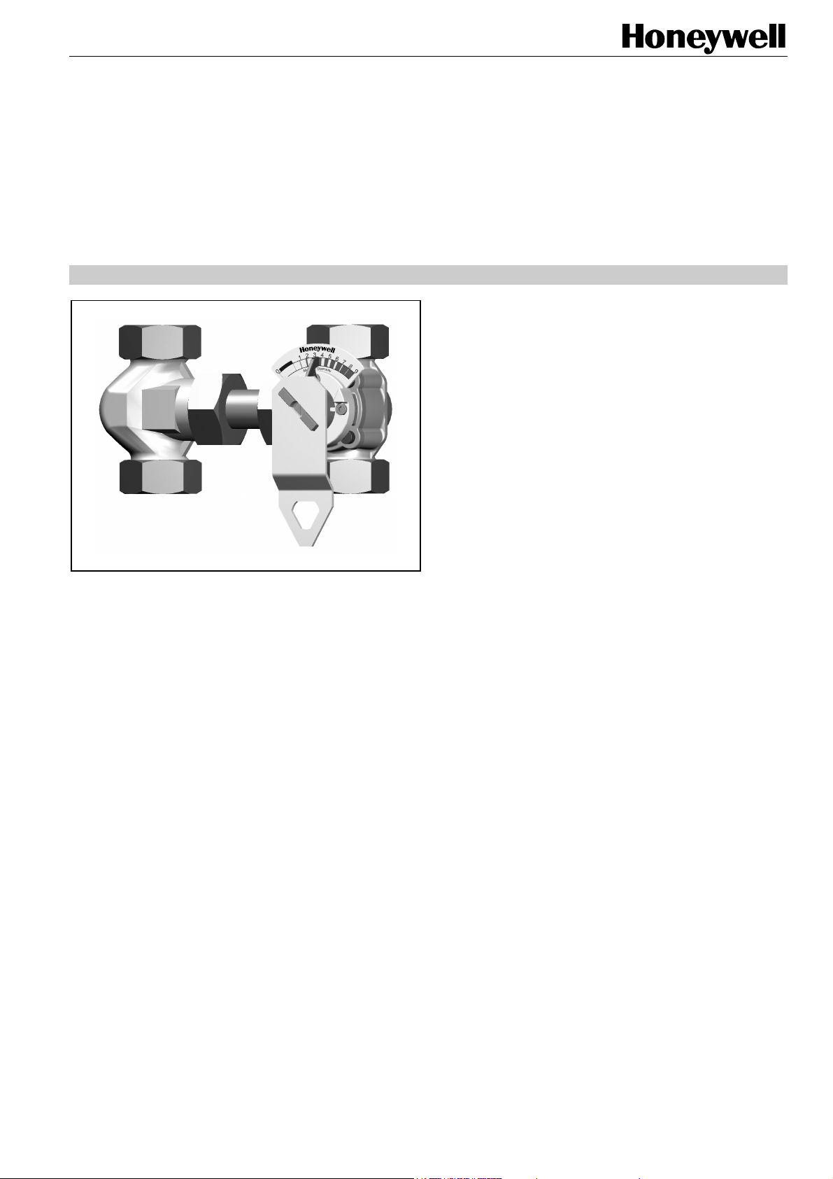
DRR/HE
THREE-WAY ROTARY VALVE PN10 AND HE25 EXTENSION
PRODUCT DATA
APPLICATION
The DRR25 Three-Way Rotary Valve provides water
temperature control in heating and air-conditioning
applications. These valves are designed for accurate mixing
control of supply water temperature and return-flow
temperature.
The sturdy construction and red brass material ensure long
operating life and high reliability when used in combination
with M6061/VMM and M7061/VRM actuators. The special
inner form of the housing and the all-around changeable
rotary plug allow the valve to be adapted to each possible
application without having to drain the system.
The DRR25 Three-Way Rotary Valve is especially designed
for applications with sludge deposition and for panel heating
(e.g. underfloor and ceiling heating systems) with oxygen
diffusion.
In combination with the distance-adjustable HE25 Extension,
use in a wide range of pre-piped systems is possible.
FEATURES
• Chrome-plated plug for long life-span
• Optimized characteristics for supply water
temperature control
• All around changeable rotary plug
• Reliable and easy mounting of electrical actuators
• Wide range of flow rates in two housing sizes
• Compact design
• Use for manifolds by accessory HE25 Extension
• Thermal insulation package included
SPECIFICATIONS
Nominal static pressure 10 bar; 1000 kPa
Maximum pressure drop dependent on type (see table
on page 3)
Leakage rate < 1% of k
Ports External threads with cap nuts
Angle of rotation 90 °
Packing Double O-ring lined
Material body Red brass
Material inner parts Chrome-plated cast iron
Medium Heating water according to
VDI 2035 (oxygen concentration
less than 0.2 g/m
Water temperatures
in the valve 2...130 °C, non-condensing
Weight dependent on type (see tables in
section "Dimensions" on page 4)
Flow characteristic equal percentage
VS
3
, pH 8...9.5)
® U.S. Registered Trademark EN0B-0611GE51 R1108
Copyright © 2008 Honeywell Inc. • All rights reserved
Page 2
DRR/HE – PRODUCT DATA
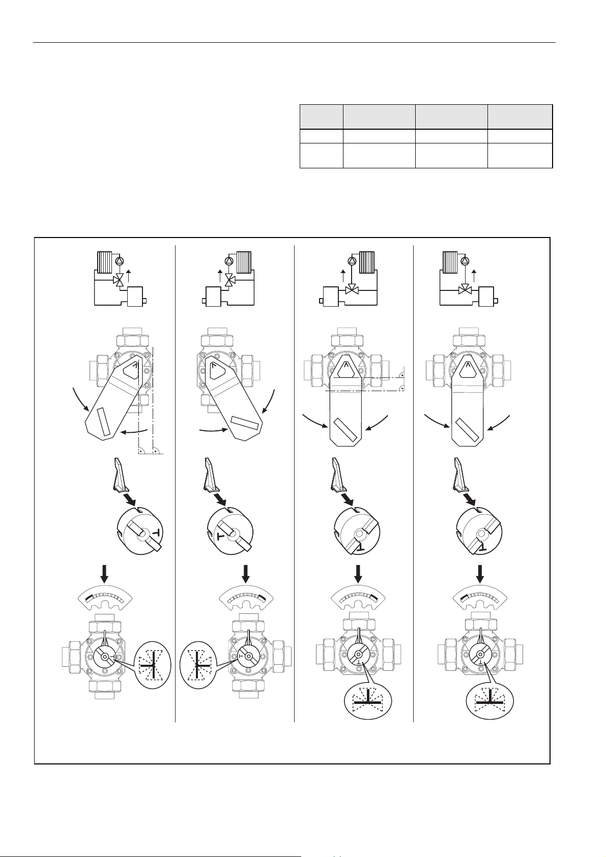
OPERATION
The valve controls a mixing water temperature by means of a
rotating plug. The plug adjusts the water flow of two inputs
with two control curves. The required flow water temperature
is achieved by adding a proportion of return water to the
boiler hot water. The DRR has special control characteristics
for optimal control performance.
MOUNTING
Adjustments for Mixing Applications
SUITABLE ACTUATORS
torque
[Nm]
10 M6061A1013 M6061L1019 M7061E1012
20
OS no.
24 Vac float.
M6061A1021 /
VMM20-24
OS no.
230 Vac float.
M6061L1027 /
VMM20
OS no.
0/2...10V
M7061E1020
/ VRM20
09 09
EN0B-0611GE51 R1108 2
09 90
Page 3

DRR/HE – PRODUCT DATA
Mounting the Actuator
SPECIFICATION AND ORDER NUMBER PER DN
OS No. DN
DRU25-2.5 25 2.5 7-12 100 10
DRU25-4.0 25 4.0 12-17 100 10
DRU25-6.3 25 6.3 17-30 100 10
DRU25-10 25 10.0 30-50 100 10
DRU25-16 25 16.0 50-70 100 10
HE25 25 - - - - - -
kvs heat flow
[m³/h] [kW] [kPa] [Nm]
nom. torque actuator
∆p
floating
M6061A1013,
M6061A1021 / VMM20-24,
M6061L1019,
M6061L1027 / VMM20
modulating
M7061E1012,
M7061E1020 / VRM20
ACCESSORIES
connection set description DN pipe size [mm] weight [kg] OS No.
Welding sockets with
gasket and cap nut
Soldering sockets with
gasket and cap nut
25 25 0.3 WTU25
25
25
25
18
22
28
0.21
0.21
0.21
LSU25-18
LSU25-22
LSU25-28
Internal threaded sockets
with gasket and cap nut
3 EN0B-0611GE51 R1108
25 25 0.21 STU25
Page 4

DRR/HE – PRODUCT DATA
DIMENSIONS
DRR
type DN a b c d e g h R weight [kg]
DRR25-2.5 25 55 32 110 89 55 51 182 1 ½ 2.48
DRR25-4.0 25 55 32 110 89 55 51 182 1 ½ 2.48
DRR25-6.3 25 55 32 110 89 55 51 182 1 ½ 2.50
DRR25-10 25 55 32 110 89 55 51 182 1 ½ 2.53
DRR25-16 25 55 32 110 89 55 51 182 1 ½ 2.51
a
b d
R
c
e
HE
type DN a b e f g R weight [kg]
HE25 25 110 42 55 0-25 51 1 ½ 1.7
=g
e
a
b
f
gg
h
R
EN0B-0611GE51 R1108 4
Page 5

DRR/HE – PRODUCT DATA
HYDRAULIC FUNCTION
Characteristics
100%
80%
60%
40%
20%
0%
Spare Parts
• O-ring (part no.: 07169 9535)
HE25
3
2
5
4
6 7 8 9
5 EN0B-0611GE51 R1108
Page 6

DRR/HE – PRODUCT DATA
V
/
VALVE DIMENSIONING
Honeywell Rotary Valves are employed mainly in hydraulic systems corresponding to the examples shown on page 2. The
rotary valve can be set quite easily. In order to obtain good control characteristics, the pressure drop in the rotary valve should
be about the same as the pressure drop in the "volume-variable" part of the pipe system, i.e. about 1.5...4.0 kPA or
15...40 mbar. The following dimensioning diagram is based on this interrelationship. The setting is obtained as follows:
1. Find heat flow in the diagram.
2. Move vertically upwards to the intersection with the corresponding ∆ϑ line. On the vertical axis, the volume flow
can be read off on the left in liters per hour.
3. Move horizontally to the right from the intersection with the ∆ϑ line into the shaded section (1.5-4.0 kPa). Here you will find
the nominal rotary valve size to be selected.
4. From this intersection, go vertically downwards. Read off the pressure drop in the rotary valve in kPa (mbar).
VOLUME FLOW (m3/h)
&
Q
&
V
1010
5
2
=
S
V
k
6
1
=
S
V
2
3
N
)
C
°
(
K
0
1
K
=
5
1
ϑ
∆
K
K
0
3
0
2
K
0
K
4
0
5
D
2
3
N
D
/
5
2
N
D
2
N
D
2
3
N
D
/
5
5
N2
D
5
2
N
D
5
N2
D
k
0
1
=
S
V
k
3
.
6
=
S
V
k
4
=
S
V
k
5
.
2
=
S
V
k
77
55
33
OLUME FLOW (m3
22
11
0.70.7
0.50.5
h)
0.30.3
0.20.2
100
10
(mbar)
(kPa)
0.3
5
3
4
0.7
0.5
5
10 100 7
7
30 20
20 200 10
HEAT FLOW (kW)
Example Given: Heat flow = 10 kW, ∆ϑ = 15 K (e.g. 70/55 °C)
70 50
50 30
2
0.2
&
Q
3
1
2
PRESSURE DROP
70
5
7
Required: Nominal rotary valve size and pressure drop
Volume flow:
&
V
Result: According to the diagram, the correct valve size is DN25, k
drop is 2 kPa or 20 mbar or 200 mm water column.
&
Q
=
∆1.163
ϑ∗
10
=
=
151.163
∗
3
/hm 0.57
4.0 (DRR25-4.0). The pressure
vs
(Factor 1.163 contains the water density 1000 kg/m3 and the specific heat capacity 4.19 kJ/kgK.
∆ϑ is the temperature difference between supply and return flow in Kelvin)
Unit Conversion 1 kW = 3600 kJ/h 1 bar = 100 kPa
= 860 kcal/h = 10 m water column
1000 kcal/h = 1.163 kW 1 mbar = 10 mm water column
Manufactured for and on behalf of the Environmental and Combustion Controls Division of Honeywell Technologies Sàrl, Rolle, Z.A. La Pièce 16, Switzerland by its Authorized Representative:
Automation and Control Solutions
Honeywell GmbH
Böblinger Strasse 17
71101 Schönaich
Germany
Phone: (49) 7031 63701
Fax: (49) 7031 637493
http://ecc.emea.honeywell.com
Subject to change without notice. Printed in Germany
EN0B-0611GE51 R1108
 Loading...