

Page 1
®
DR45AW Truline
Open Channel Flow
44-45-03-11
8/02
Page 1 of 12
Circular Chart Recorder
Function
The Model DR45AW is a Truline
recorder that has been designed
to perform as an Open Channel
Flow recorder. It combines the
broad capabilities of Honeywell’s
Truline recorders with special
features needed to serve the
water and waste water industries.
These features include:
• accurate flow measurement
• V-notch, rectangular, and
Cipolletti weir calculations
• Parshall flume calculation
• Palmer-Bowles flume calculation
• up to four optional totalizers (one
per input) that can be
automatically scrolled on the
display
• optional NEMA4X door
• optional non-control pulse output
counter alarm
• adjustable low flow cutoff
Honeywell’s Model DR45AW
Truline recorder is a one to fourchannel, microprocessor-based,
circular chart recorder. Its “onepen” stylus printhead produces up
to four analog traces and prints
alphanumeric chart data on a
blank heat-sensitive chart. All four
traces share the same time line
reference, which the Truline
prints. This eliminates the error
caused by pen alignment offsets
in conventional pen designs.
Since the Truline prints the chart
and generates the analog traces
at the same time, there is no error
due to variations in chart size
caused by changes in
temperature and humidity.
In addition to printing informative,
accurate chart records, the Truline
recorder alternately displays
process variable values for all
channels in the selected
engineering units.
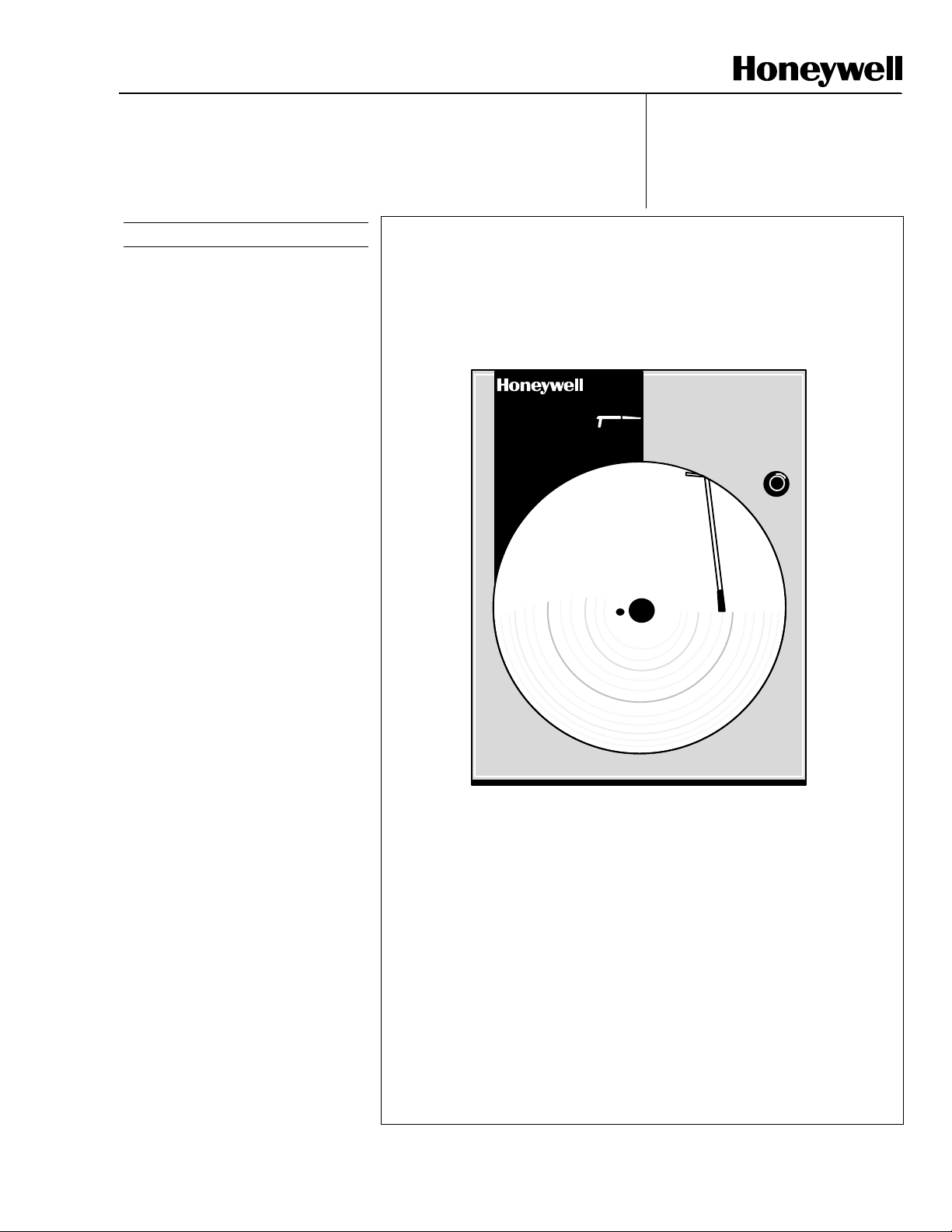
Figure 1—Truline recorder provides printed chart data and continuous
digital indication of process variable value.
1559
3IN 86.0
ruline
Specification
20889
Industrial Measurement and Control, 1100 Virginia Drive, Ft. Washington, PA 19034
Printed in U.S.A. © Copyright 2002—Honeywell
Page 2

44-45-03-11
Page 2
Features
Five Open Channel Flow
Elements
They are:
• V Notch Weir
• Rectangular Weir
• Cipolletti Weir
• Parshall Flume
• Palmer-Bowles Flume
Pulse Output Counter Alarm
provides 2 configurable time
duration relay output when a
selected incremental change in
volume has occurred. The pulse
output relay can be reset from the
keyboard.
Low Flow Cutoff
each input being used for
totalization. It allows the user to
select a percent of flow range value
that inhibits the totalizer’s
accumulator whenever the input
signal is less than the selected
value.
Dual Displays
fluorescent, alphanumeric digital
displays make pasteurization
process data instantly available to
your operation.
User Configurable
language prompts, coupled with
simple keystroke sequences, make
configuring the recorder easy and
straightforward. You can set and/or
alter operating parameters to fit
your requirements without recalibration.
All Purpose Chart
purpose, blank chart eliminates the
need for ordering and stocking
several types of charts. Users can
design the chart to match their
specific application.
Four Channel Input
channels that monitor process
variables from a variety of sensor
types help reduce panel space
requirements.
“One-pen” Stylus Print Head
prints configurable alphanumeric
chart data including time and trend
lines. This automatically
compensates for chart width
variations caused by changes in
the ambient relative humidity.
— are configurable.
—
— available for
— bright, vacuum
— English
— one all-
— up to four
—
Time/Date
— To guard against
unauthorized chart advancement,
an integral real-time clock provides
accurate timing for the recorder’s
time and date printing, and also any
operator changes. A 10-year life,
battery backup assures correct
timing even when power fails.
External Interface
Selections
• Four Totalizers — up to four
totalizers (one for each input) are
adjustable. A manually adjustable
totalizer function can be selected
to make corrections to the
accumulated value as a result of
power outage.
• Modbus
Communications —
option allows you to network your
recorders to take advantage of
overall monitoring of the system
using an RS485 network.
• Alarm Output
— Ties “soft”
alarms to up to two integral SPST
relays to activate user’s external
equipment.
• Digital Input
— Allows users to
initiate, from a remote location,
through two dry contact closures,
selected functions such as auto to
manual control mode, direct to
reverse controller action, or
initiate autotune.
• Timer — This optional feature
provides a configurable time
period of 0 to 99 hours, 59
minutes or units of minutes and
seconds. It can be started via the
keyboard, alarm 2, or by a digital
input. The timer output is Alarm 1,
which energizes at the end of the
Timer Period. Alarm 1 can be
automatically reset. The Timer
Period can be changed between
each batch. Status is shown on
the lower display.
• Auxiliary Output
— there is also
a 4 to 20 mA current output
available.
Options
• Door Options — Choice of gray,
black or blue doors with standard
latch or optional lock.
and FM approved NEMA4X door
available.
Optional UL
• Chart Illumination — Lights the
chart area to improve readability
in lower light areas.
•Math Functions
Algorithms
— pre-configured
algorithms for easy implementation into other control loop with
Ratio and Bias.
Summer - will add three inputs
with the result as the derived PV.
Multiplier/Divider - uses three
analog inputs to calculate a
derived PV with or without square
root.
Multiplier - multiplies three inputs
with the result as the derived PV
with or without square root.
Subtractor/Multipler - the
difference between input 1 and
input 2 is multiplied by input 3.
Input High/Low Select - specifies
the PV as the higher or lower of
two inputs.
Polynomial Curve
Characteristics
— A fifth order
polynomial equation can be used
on any one of the analog inputs.
• Approval Body Options — FM
approval, CSA certification and
UL Listing or a combination is
available.
• Customer ID Tag
— (30
characters max.)
• CE Mark
— Conformity with
73/23/EEC, Low Voltage
Directive and 89/336/EEC EMC
Directive.
User Configurable
In the DR4500A Series recorder,
microprocessor control replaces
conventional electromechanical
recording techniques. Its software
primarily determines the recorder's
capabilities. Since Honeywell has
preprogrammed a variety of
functional capabilities into the
recorder, you only have to configure
those functions that are specific for
the given application. You configure
the recorder using English language
prompts that appear in the digital
displays. The configuration data
(type of input, chart speed, chart
range, alarm settings, etc.) are
stored in non-volatile memory for
safe keeping in the event of a power
failure.
Page 3
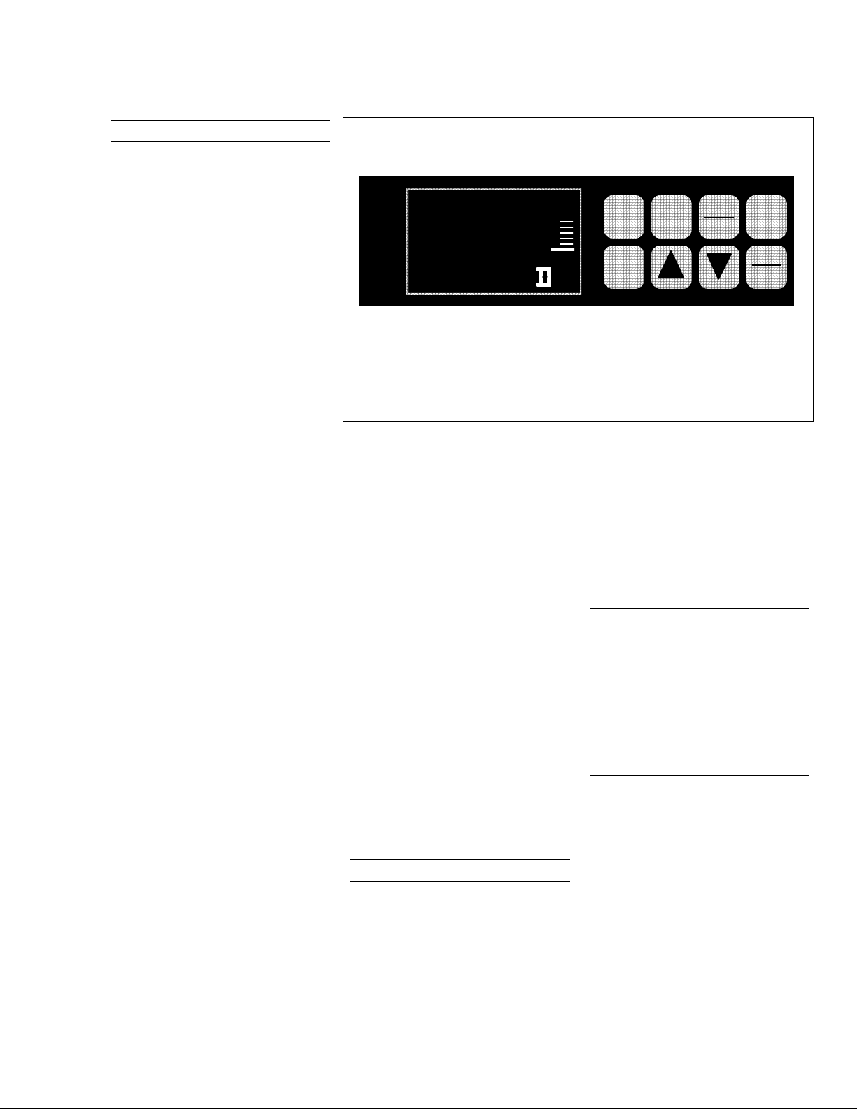
Operator Interface
Two digital displays present the
process variable (PV) value and
by key selection, the deviation
from reference input; totalization
value; or engineering units as
desired. The lower display can
also be set to hold or scroll.
In configuration mode, digital
displays are pre-empted by
English language prompts and
values that you use to enter
configuration data. Indicators light
to show alarm condition, which
channel PV is on display, use of
remote set point, and selected
temperature unit.
Input Processing
The input can be one of many
standard low-level electrical
signals. Since inputs are isolated,
users can connect different types
of input signals to multi-channel
models in any combination. The
input type and range are user
configurable for hassle-free
actuation changes in the field.
Ranges are easily expanded and
compressed within their span
limitations to meet specific
measurement needs. Users can
select upscale or downscale
sensor break protection for many
of the actuations.
Each input is sampled at a rate of
3 times per second for 1 or 2
inputs, or 3 times in 2 seconds for
3 or 4 inputs. Each sample is
amplified and then converted to a
digital signal, which is isolated and
passed to the microprocessor. A
digital filter with configurable time
constants lets users apply input
signal smoothing as desired. All
non-linear inputs are linearized by
the microprocessor.
ALM
CHN
RSP
OUT
Figure 2—Operator interface includes displays and keypad for
comprehensive interaction with the recorder and the process.
An integral 24 Vdc power supply,
along with 4-20 mA input configuration, allows direct operation
with up to two transmitters without
the need for any additional/
external transmitter power supply.
To totalize a variable, such as a
flow signal, users select the
applicable input and set the digital
display scaling factor through
configuration. This eliminates the
need for additional integration
hardware including a mechanical
counter. The totalizer has an eight
digit display and 14 digit printing
on the chart. A grand total can be
enabled to print the sum of all the
totalizers. Also, there is the
capability to reset the totalizer
remotely with digital inputs and a
low flow cut off can be set in
percent of range, below which the
applicable totalizer does not
increment.
All DR4500A Series recorders
include self-diagnostic systems
that check critical operations and
provide error messages to alert
users about detected faults.
F
1
X HR
CHRT SP
Diagnostics
A
FUNC
LOWR
DISP
MAN
AUTO
%
SET
UP
Power-up self-diagnostics is a
microprocessor controlled
diagnostic program that runs tests
on selected circuitry when the
recorder is powered up. A “key”
test allows a user to initiate, on
demand, a self-diagnostic routine
that checks the keypad and front
panel displays.
Process Interface
Power, input, and output wiring
connect to terminations inside the
case. Knockouts in the sides and
bottom of the case accept conduit
connections for convenient wire
entry.
Construction
The DR4500A Series recorder is
housed in a molded case which
can be panel or surface mounted.
A glass or acrylic window,
gasketed door protects internal
components from harsh industrial
environments while allowing easy
access to the chart and operator
interface. Circuitry is partitioned
on printed circuit boards for ease
of service.
NEMA4X door is also available.
A UL and FM approved
44-45-03-11
Page 3
CHART
RUN
HOLD
20951
Page 4
44-45-03-11
Page 4
Recording and Printing
Both the chart and the printhead
are driven by the stepper motors,
which are controlled by the
microprocessor allowing precise,
maintenance free operation.
Since chart speed is configurable,
users can easily alter the chart
speed through the keypad. Gear
changing or additional motors are
no longer required.
The microprocessor uses the
configured chart range data as
well as the input data to determine
the proper printhead position. The
stepper motor accurately positions
the printhead drive. By using a
“one-pen” printhead that is
capable of printing alphanumeric
characters, users can now set
various “printed” chart data
through configuration. This
versatile recorder automatically
performs this function by printing
pertinent identifying data on the
border of the chart. This data can
include: listing of the monitored
variables, range of each variable,
time references, and totalization
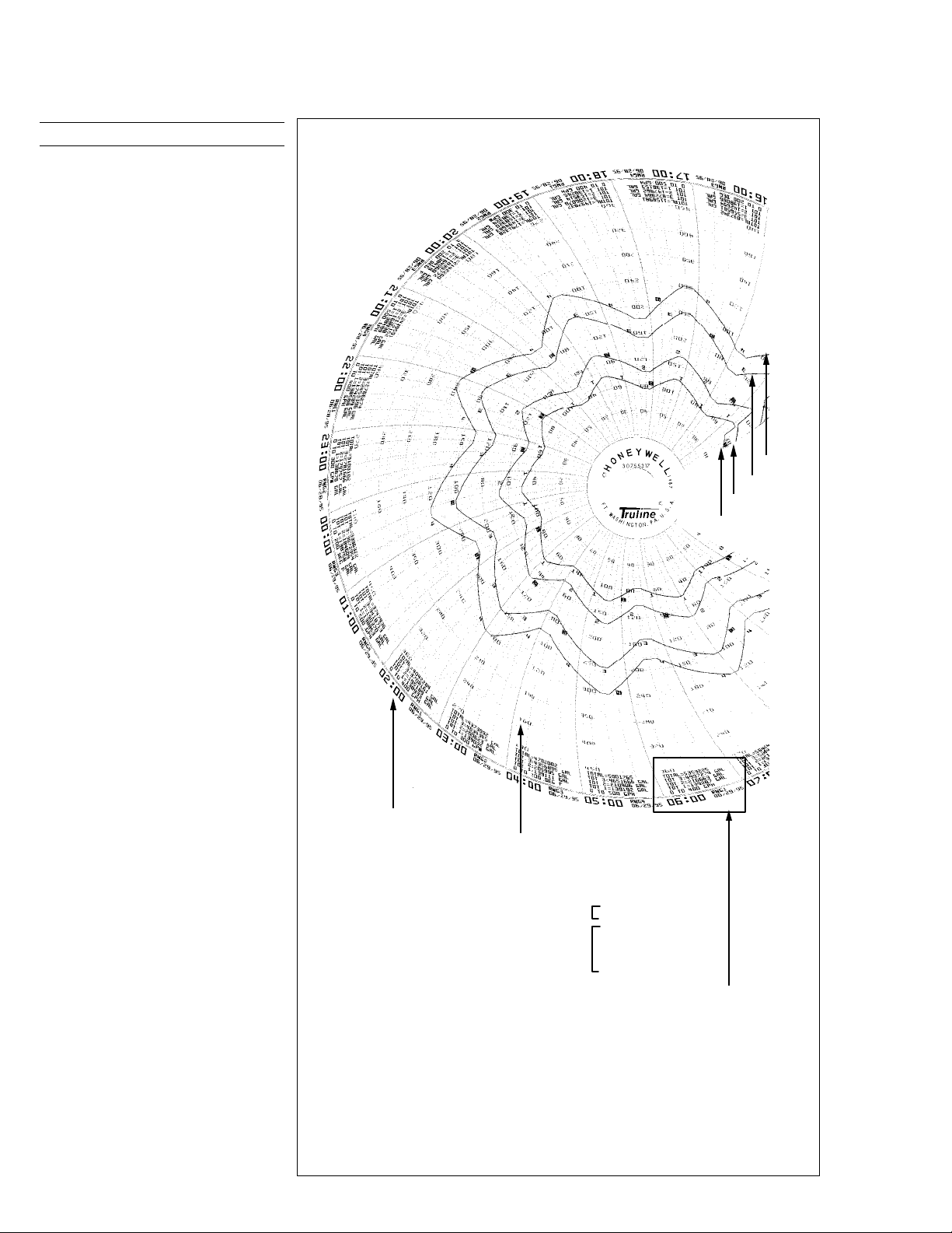
numbers. The Figure 3 reproduction of a 12-inch circular chart
illustrates some of these recording
features.
Input #4
Input #3
Input #2
Input #1
This data, plus printed time lines
and engineering units of scale,
eliminate the need to maintain an
inventory of a variety of preprinted
charts.
The Truline recorder uses a dot fill
technique from a microprocessor
algorithm to produce a continuous
analog trace of a process variable.
Time/Date
Range
Range Values
Grand Total
Individual Totals
1, 2, and 3
Figure 3—Sample of Printed Chart.
Header
TOTAL=5353225
TOT 3=4997274 GAL
TOT 2=216663 GAL
TOT 1=139287 GAL
0 TO 400 GPM
22847
Page 5

Specifications
Design
44-45-03-11
Page 5
Digital Indication Accuracy
Minimum Input Span
Input Impedance
Source Impedance
Sampling Rate
Input Filter
Digital Displays
Indicators
Transmitter Supply Voltage
Case/Door
Chart
1 digit
Range is fully configurable with span limitation of the operating range selected.
4-20 mA dc: 250 ohms
0-10 Vdc: 200K ohms
All others: 10 Megohms
RTD: 100 ohms per lead maximum
Each input sampled 3 times a second (1 or 2 inputs);
3 times in 2 seconds (3 or 4 inputs).
Software: Single pole low pass section with selectable time constants (off to 120
seconds).
Vacuum fluorescent, alphanumeric.
A six-digit display dedicated to the process variable.
Alternate information displayed during configuration mode.
An eight-digit display shows key selected operating parameters. Also provides
guidance during configuration.
Channel PV display (CHN 1, 2, 3, or 4)
Alarm status (ALM 1, 2)
Controller Output (OUT 1 or 2)
Remote Set Point (RSP)
Temperature unit (F or C) or Engineering units
Controller’s mode (A or MAN)
22 to 26 Vdc at input terminals (50 mA dc at 24 Vdc)
Molded, foamed-Noryl** with gasketed door to meet NEMA 3 enclosure
requirements. Panel gasket available separately.
An optional UL and FM approved NEMA4X door is also available.
12-inch (304.8mm) diameter chart. Plain thermal-sensitive paper.
Wiring Connections
Color
Approval Bodies
Dimensions
Weight
Mounting
WARRANTY/REMEDY
Honeywell warrants goods of its manufacture as being free of defective materials and faulty workmanship. Contact your local
sales office for warranty information. If warranted goods are returned to Honeywell during the period of coverage, Honeywell
will repair or replace without charge those items it finds defective. The foregoing is Buyer's sole remedy and is in lieu of all
other warranties, expressed or implied, including those of merchantability and fitness for a particular purpose.
Specifications may change without notice. The information we supply is believed to be accurate and reliable as of this printing.
However, we assume no responsibility for its use.
While we provide application assistance personally, through our literature and the Honeywell web site, it is up to the customer
to determine the suitability of the product in the application.
Terminals inside the case
Case: Black
Door (standard): Caribbean Blue, Black or Gray
U.L. approval depending on model. Consult Model selection Guide for information.
FM approved for Class I, Div 2, Groups A, B, C, D areas depending on model.
See Figure 4
13.2 lb. (6 kg)
Panel or surface mounted. Some adapter kits available for existing panel cutouts.
Page 6

44-45-03-11
Page 6
Specifications, continued
Performance
Number of Inputs
Types of Input
Actuation
Thermocouples2
B
E
E (low) -200 to 1100 -129 to 593
J 0 to 1600 -18 to 871
J (low) 20 to 770 -7 to 410
K
K (low) -20 to 1000 -29 to 538
NNM (Ni Ni Moly) 32 to 2500
NIC (Nicrosil
Nisil)
R
S
T -300 to 700 -184 to 371
T (low) -200 to 600 -129 to 316
W5W26
W5W26 (low) 0 to 2240
Radiamatic (RH) 1400 to 3400 760 to 1871
RTDs2
Platinum
100 ohms
500 ohms
2
Includes reference junction calibration of ± 0.01 degrees using standard “ice bath” method of calibration. Factory calibration at reference
± 1.2˚F. Note that factory calibration may vary by as much as ± 10 microvolts or ± 0.3 ohms for RTDs which means recalibration may be
required to achieve stated accuracy.
One channel model: One input
Two channel model: Two inputs
Three channel model: Three inputs
Four channel model: Four inputs
Range
Reference Accuracy
˚F ˚C ± ˚F ± ˚C
105 to 3300
105 to 150
150 to 500
500 to 1000
1000 to 3300
-454 to 1832
-454 to -202
-202 to 1832
-320 to 2500
-320 to 0
0 to 2500
32 to 500
500 to 2500
0 to 2372 -18 to 1300
0 to 3100
0 to 500
500 to 3100
0 to 3100
0 to 500
500 to 3100
0 to 4200
0 to 600
600 to 3600
3600 to 4200
0 to 600
600 to 2240
–300 to 900
–300 to 900
41 to 1816
41 to 66
66 to 260
260 to 538
538 to 1816
-270 to 1000
-270 to -130
-130 to 1000
-196 to 1371
-196 to -18
18 to 1371
0 to 1371
0 to 260
260 to 1371
-18 to 1704
-18 to 260
260 to 1704
-18 to 1704
-18 to 260
260 to 1704
-18 to 2315
-18 to 316
316 to 1982
1982 to 2315
-18 to 1227
-18 to 316
316 to 1227
–184 to 482
–184 to 482
42.00
14.00
3.00
1.50
18.00
1.00
0.50 0.30 0.20
0.40 0.22 0.06
0.20 0.11 0.04
1.25
0.60
0.30 0.16 0.05
0.75
0.50
1.0 0.55 0.01
2.00
1.00
2.00
1.00
0.60 0.35 0.07
0.40 0.22 0.07
1.40
1.30
1.60
1.10
1.00
1.00 0.55 0.10
0.40
0.20
23.00
7.70
1.70
0.80
10.00
0.55
0.70
0.35
0.40
0.30
1.10
0.55
1.10
0.55
0.77
0.70
0.90
0.60
0.55
0.22
0.11
Temp. Stability ±
Degrees Error Per 1
Degree ∆T
2.00
2.00
0.50
0.20
0.70
0.35
0.18
0.09
0.09
0.07
0.25
0.13
0.23
0.13
0.17
0.17
0.29
0.14
0.10
0.05
0.05
Page 7

44-45-03-11
Page 7
Specifications, continued
Range
Reference Accuracy
--
--
--
--
--
0.10%
0.05%
0.05%
0.05%
0.10%
Types of Input
Actuation
Thermocouples2
Linear
Milliamperes dc
Millivolts dc
Volts dc
Relative Humidity
Platinum Wet/Dry
˚F ˚C ± ˚F ± ˚C
4 to 20
0 to 10
10 to 50
1 to 5 (can be
calibrated 0 to 5)
0 to 10
100 ohm Input
Wet/Dry
Bulb*
%RH3
–130 to 392
Measured %RH
0 to <20
20 to 100
–90 to 200
Dry Bulb Range
˚F ˚C
–103 to 212
35 to 40
>40 to 100
100 to 212
0.30
–75 to 100
2 to 4
>4 to 38
38 to 100
Configurable Parameters: These parameters can be set through the keypad.
Group Parameters Setting Range or Selection Resolution
CHART
TIME
PEN 1, PEN 2,
PEN3, PEN4
AUX OUT 1 Auxiliary Output
2
Includes reference junction calibration of ± 0.01 degrees using standard “ice bath” method of calibration. Factory calibration at reference
± 1.2˚F. Note that factory calibration may vary by as much as ± 10 microvolts or ± 0.3 ohms for RTDs which means recalibration may be
required to achieve stated accuracy.
3
The RH calculation is inoperative when temperature goes below 32˚F (0˚C) or above 212˚F (100˚C). However, the dry bulb temperature will
be monitored to -103˚F (-75˚C). Accuracy stated is for Truline Recorder only and does not include remaining system accuracies.
*IEC Alpha (
**Below 8 hrs. chart speed and 24 hrs. chart speed with Abrasion Resistant Pen printing may be degraded.
α) = 0.00385 Ω/Ω/˚C
Chart speed
Hours per revolution
Time Div
Minor Div
Continue
Chart Name
Header
Rem Chart
Wake Minute
Wake Hour
Wake Day
Wake Month
Minutes
Hours
Day
Month
Year
Day
Pen 1
Pen 1 input
Chart 1 high range value
Chart 1 low range value
Major chart division
Minor chart division
Range 1 Tag
Pen 1 On
Pen 1 Off
4 mA Val
20 mA Val
8 hrs, 12 hrs, 24 hrs, 7 days, or selected hours per rev
6 to 744 hrs** (12 hrs. for Abrasion Resistant Pen)
8 to 24
4 or 8
Yes or No (Chart rotation beyond 360 degrees)
Up to six characters
Yes or No
None, Extsw1, Extsw2, Alarm1,2, 3, 4, 5, or 6, Time
0 to 59
0 to 23
0 to 31
0 to 12
1 to 59
0 to 23
1 to 31
1 to 12
4-digits
Monday to Sunday
Disable or Enable
Input 12,3,4, Output, SP, Dev, Dgtl1, Dgtl2, Out2, SP2,
Dev2
–999.0 to 9999
–999.0 to 9999
2 to 10
2 to 10
Up to five characters
0 to 100% of chart
0 to 100% of chart
Disable, In1, In2, PV1, PV2, Dev1, Dev2, Out 1 (2), SP 1(2)
Lower Scaling Factor
High Scaling Factor
--
--
--
--
--
0.16
Reference
Accuracy
˚F ± ˚C
±
2% RH
2% RH
1% RH
1% RH
Temp. Stability ±
Degrees Error Per 1
Degree ∆T
0.004% /
0.004% /
˚F
˚F
0.004% /˚F
0.004% /˚F
0.004% /˚F
0.03
Temp. Stability
53 to 104˚F/
12 to 40˚C
0.11% RH/˚F
0.11% RH/
0.06% RH/
0.03% RH/
˚F
˚F
˚F
0.1
0.1
1
1
Page 8

44-45-03-11
Page 8
Specifications, continued
Configurable Parameters, continued: These parameters can be set through the keypad.
Group Parameters Setting Range or Selection Resolution
INPUT 1,
INPUT 2,
INPUT 3,
INPUT 4
TOTAL1, TOTAL2,
TOTAL3, TOTAL4
PULS OUT
Relay Output 1
Relay Output 2
OPTIONS
TIMER Timer
Decimal point location
Units
Actuation type
Transmitter characterization
High range value
Low range value
Flow transmitter
Flow Rate
Weir type
Parshall Flume size
Palmer-Bowles Flume type
V Notch Weir angle
Weir or Flume width
Weir or Flume Maximum
Height
Weir or Flume Minimum
Height
Low Flow Cutoff (% of Max.
Flow)
Input compensation
Filter Input
Sensor break protection
Total
Reset total
Total 1(2,3,4)
Total engineering units
Scaling factor
Resettable
Totalizer adjustment
Adjustment Rate (average
flow)
Adjustment Time Duration
Execute Totalizer
Adjustment
Pulse Counter Selection
Totalizer Selection
Pulse Setpoint Value
Setpoint Scale Selection
Pulse Width
Pulse Counter Reset
Reject Frequency
Relative Humidity
Atm. Pressure
Scroll
Deviation
Deviation Setpoint
Period
Start
Ldisplay
Reset
Increment
None, 1 (XXX.X), 2 (XX.XX), or 3 (X.XXX) –
one decimal place only for non-linear inputs
F, ˚C or engineering units
˚
See input types
All non-linear input types, linear, square root
–999.0 to 9999
–999.0 to 9999
None, Height, or Flow
CFS, GPS, GPM, GPH, MGD, AFD, CMS, CMM, CMH,
LPS, MLD, HMD, LPM, LPH, KC/M, KG/H
V Notch, Rectangular, Cipolletti
1 inch, 2 inch, 3 inch, 6 inch, 9 inch, or defined by user.
4,6,8,10,12,15,18,21,24,27,30,36,42,48,60, or 72 inch
30, 60, 90, 120 degrees
0 to 9999 inches
0 to 9999 inches (represents Max. input signal)
0 to 9999 inches (represents Min. input signal)
0 to 100%
–999.0 to 9999
0 to 120 sec
None, Up or Down (burnout)
Read only
Yes or No
Input 1,2,3,4, PV1, Etime
Desired alphanumeric title
1, 10, 100, 1000, 10,000, 100,000 or 1E6
No, Local, Ext Sw1, Ext Sw2
Yes or No (in case of power outage)
0 to 9999 (uses unit selected)
0 to 9999 (uses unit selected)
Yes or No (no adjustment made until YES selected)
Yes or No
TOTAL 1, TOTAL 2, TOTAL 3, or TOTAL 4
0 to 9999
1, 10, 100, 1000, 10000, 100000, or 1E6
0.5 sec., 1 sec., 5 sec.
Yes or No
60 or 50 Hz
Yes or No
590 to 800
None, 1 sec, 2 sec, 3 sec
None, SetPnt, Chan 1
-999.0 to 9999
Enable/Disable
0.00 to 99:59
Run/Hold Key or Alarm 2
Time Remaining or Elapsed Time
Run/Hold key or Alarm 1
Minut or Second
1
1
1
1
1
1
1
1
Page 9

44-45-03-11
Page 9
Specifications, continued
Configurable Parameters, continued: These parameters can be set through the keypad.
Group Parameters Setting Range or Selection Resolution
Input Algorithm Input Algorithm
K Coefficient
PV High Limit
PV Low Limit
Ratio A
Bias A
Ratio B
Bias B
Ratio C
Bias C
PolynomialCharacterization
Polynomial coefficient C0
Polynomial coefficient
C1, C2, C3, C4, and C5
ALARMS
(1,2,3,4,5,6))
EVNT MSG
LOCKOUT
STATUS
SP Value
SP Type
Alarm Type
Alarm Scaling Multiplier for
Totalizer Alarm
Alarm Hysteresis
Event 1 (2,3,4,5,6)
MESSAGE 1 (2,3,4,5,6)
POSITION 1 (2,3,4,5,6)
Password
Lockout (software and/or
hardware)
Change
Version
Failsafe
RAM Test
Configuration Test
Calibration Test
Comm Test
Fact CRC
Battery Test
Options
Alarm Output
Auxiliary Linear Output (Optional)
Digital Input
Totalizers
Summer w/ratio-bias, multiplier with or without square
root, multiplier/divider with or without square root,
subtractor multiplier, or High/Low Select.
72.0...... to 1000
-999 to 9999
-999 to 9999
-20 to +20
-999 to 9999
-20 to +20
-999 to 9999
-20 to +20
-999 to 9999
None, Input 1, Input 2, Input 3, Input 4
–99.99 to 99.99
–9.999 to 9 999
72.0...... to 9999
None, Input 1 (2, 3, 4), RH/PV, Dev, Output,Total 1(2,3,4)
High or Low
1, 10, 100, 1000, 10000, 100000, 1E6
0.0 to 100% of span
EXTSW1, EXTSW2, ALARM 1, ALARM 2, ALARM 3,
ALARM 4, ALARM 5, ALARM 6
Message for event (up to 6 characters)
Chart position for message printing (0 to 100%)
Up to four characters
None, Calib, +Conf, Max (hardware configuration
lockout—option)
Used if changing Password
Latest Software Version
Yes or No
Pass or Fail
Pass or Fail
Pass or Fail
Pass or Fail
Pass or Fail
Pass or Fail
Two SPST electromechanical relays
Relay Contact Ratings:
Resistive Load: 1A @ 120 Vac, 1/2A @ 240 Vac.
21 mAdc maximum into a negative or positive grounded load or non-grounded load
of 0 to 1000 ohms.
Output range can be set between 0 to 21 mA, as direct or reverse action. It can be
configured to represent any one of 10 parameters, Deviation, or Control output. The
range of the auxiliary output, as a function of the selected variable, can be scaled.
This output can be used as a second current output for current duplex outputs.
Resolution: 12 bits over 0 to 21 mA
Accuracy: 0.2% of full scale
Temperature Stability: 0.03% F.S./°C
+20 Vdc source for external dry contact or isolated solid state contacts. Selects one
configured input.
Up to four totalizers on DR45AW Model. Eight digit “totals” with multiplier on digital
display; 14-digit totalization printout on chart. When enabled, a grand total can be
printed where total #4 is normally printed.
0.1
Page 10

44-45-03-11
Page 10
Specifications, continued
Options, continued
Calculations
Math Algorithms
CE Conformity (Europe)
Product Classification:
Enclosure Rating:
Installation Category (Over-voltage
Category)
Pollution Degree:
EMC Classification
Method of EMC Assessment
Declaration of Conformity
Flow Equations
Weir and Flume
Note: When a metric flowmeter is
selected, height and width
parameters are read as
centimeters.
Example
Open channel flow calculations available.
Eight algorithms available:
A + B + C (summer)
√A • B/C (square root multiplier/divider)
√A • B • C (square root multiplier)
A • B/C (multiplier/divider)
A • B • C (multiplier)
(A – B) • C (difference multiplier)
High/Low Select between Input 1 and 2
Polynomial Equation – Fifth order
provides equation
This product is in conformity with the protection requirements of the following
European Council Directives: 73/23/EEC, the Low Voltage Directive, and
89/336/EEC, the EMC Directive. Conformity of this product with any other
“CE Mark” Directive(s) shall not be assumed.
Class I: Permanently Connected, Panel Mounted Industrial Control Equipment with
protective earthing (grounding). (EN 61010-1)
Panel Mounted Equipment, IP 00, this recorder must be panel mounted.
Terminals must be enclosed within the panel. Front panel IP 65 (IEC 529)
Category II: Energy-consuming equipment supplied from the fixed installation.
Local level appliances, and Industrial Control Equipment. (EN 61010-1)
Pollution Degree 2: Normally non-conductive pollution with occasional conductivity
caused by condensation. (Ref. IEC 664-1)
Group 1, Class A, ISM Equipment (EN 55011, emissions), Industrial Equipment (EN
50082-2, immunity)
Technical File (TF)
51197639-000
For the following equations, both height and width are measured in feet.
V NOTCH WEIR
30 DEG Q =.676 H
60 DEG Q = 1.42 H
90 DEG Q = 2.49 H
120 DEG Q = 4.33 H
RECTANGULAR WEIR
Q = 3.33 (W – 0.2H) H
Width must be greater than three times the height.
CIPOLLETTI WEIR
Q = 3.37 W (H)
PARSHALL FLUME
Throat Width Flow (ft
1 inch Q = 0.338 H
2 inches Q = 0.676 H
3 inches Q = 0.993 H
6 inches Q = 2.060 H
9 inches Q = 3.068 H
X inches Q = 4 W H(
(X is greater than 12 inches)
Where:
W = Width (in feet)
Q = Flow (in cubic feet per second)
H = Height (in feet)
User has a 3-inch Parshall Flume and measures height as two feet. Flow is
calculated as: Q = 0.993 (2)
2.5
1.5
1.5
cubic feet per second
1.55
1.55
1.547
1.58
1.53
1.522 W0.026
1.547
• where:
A = Input 1 • ratio A + bias A
B = Input 2 • ratio B + bias B
C = Input 3 • ratio C + bias C
Limit of Ratio = -20 to +20
Limit of Bias = -999 to +9999
cubic feet per second
2.440
cubic feet per second
2.475
cubic feet per second
2.5
cubic feet per second
cubic feet per second
3
/sec)
cubic feet per second
cubic feet per second
cubic feet per second
cubic feet per second
cubic feet per second
) cubic feet per second
= 2.9 cubic feet per second
(See Note.)
Page 11

44-45-03-11
Weir and Flume, continued
*Equations provided by Plasti-Fab
Inc.
Where:
W = Width (in feet)
Q = Flow (in cubic feet per second)
H = Height (in feet)
PALMER-BOWLUS FLUME
Type Flow (ft3/sec)
4 inches Q = 1.73 (H + .00588)
6 inches Q = 2.071 (H + .005421)
8 inches Q = 2.537 (H + .01456)
10 inches Q = 2.843 (H + .0161)
12 inches Q = 3.142 (H + .017)
15 inches Q = 3.574 (H + .0168)
18 inches Q = 3.988 (H + .01875)
21 inches Q = 4.223 (H + .039)
24 inches Q = 4.574 (H + .0408)
27 inches Q = 4.97 (H + .038)
30 inches Q = 5.022 (H + .0625)
36 inches Q = 5.462 (H + .08)
42 inches Q = 6.12 (H + .078)
48 inches Q = 6.626 (H + .085)
60 inches Q = 7.183 (H + .126)
72 inches Q = 7.839 (H + .155)
1.9573
1.9724
1.9530
1.9362
1.9062
1.8977
1.9619
1.9497
1.9269
1.9663
1.991
1.9628
1.9586
1.9833
1.9871
*
1.9025
Environmental and Operating Conditions
Parameter Reference Rated Extreme Transport and storage
Ambient
Temperature
Relative Humidity (%RH)
Vibration
Frequency (Hz)
Acceleration (g)
Mechanical Shock
Acceleration (g)
Duration (ms))
Mounting Position from
Vertical
Tilted Forward
Tilted Backward
Tilted to Side (
± )
Power Requirements
Voltage (VRMS)
Frequency (Hz)
Power Consumption
67 to 77˚F
19 to 25
˚C
58 to 131
15 to 55
0 to 55* 10 to 90*
0
0
0
0
˚
5
˚
5
˚
5
119 to 121
238 to 242
49.8 to 50.2
59.8 to 60.2
0 to 70
0.1
1
30
˚
5
˚
30
˚
10
102 to 132
204 to 264
49 to 51
59 to 61
24 watts maximum
˚F
˚C
32 to 131˚F
˚C
0 to 55
–40 to 151˚F
–40 to 66
5 to 90* 5 to 95*
0 to 200
0.2
5
30
˚
5
˚
90
˚
20
102 to 132
204 to 264
48 to 52
58 to 62
0 to 200
0.5
20
30
Any
Any
Any
N/A
N/A
N/A
N/A
˚C
Page 11
General Reference Data
Stray Rejection
Static Charge Effects
Line Noise Effects
Stylus Life
Technical Assistance
* The maximum rating only applies up to 104 ˚F (40 ˚C). For higher temperatures, the RH specification is de-rated to maintain constant
moisture content.
Common Mode Rejection Ratio: 120dB or 1 LSB (whichever is greater) at 60 Hz with
maximum source impedance of 100 ohms.
Normal Mode Rejection Ratio: 60dB with a 100% span peak-to-peak maximum at 60 Hz.
Exposed panel surfaces capable of withstanding a discharge from a 250pf capacitor charged to
10 KV through 100 ohms.
Field terminals for connecting power line to recorder can withstand the IEEE Surge Withstanding
Capability Test to a level of 2.5KV.
Typically capable of printing one chart per day for five years under clean room conditions.
Toll-free 800 number puts technical assistance only a phone call away.
Page 12

44-45-03-11
Page 12
Dimensions:
Standard DR4500
17.5
0.69
Bottom view
millimeters
321
12.6
inches
Reference
20.3
0.8
321
12.6
419
16.5
163
6.4
196
7.7
Surface mounting
14.6
370
181
7.1
Short wing latch :
Double bit latch :
Left side view
14.5
.57
.19
5
NEMA4X DR4500
17.5
0.69
Bottom view
321
12.6
106
4.2
Reference
20.3
0.8
321
12.6
106
4.2
142
5.6
142
5.6
11.0
.43
355
14
Front view
387
15.25
Front view
NEMA4X
438
17.25
z
z
z
Surface mounting
z
z
Back view
zzzzz
zzzzz
Back view
322
12.7
z
z
z
z
z
322
12.7
Panel cutout (all models)
Ordering Information
For complete ordering information, request Model Selection Guide 44-45-16-07 for DR4500A Series
Circular Chart Recorder.
Honeywell offers a full line of sensors and transmitters that produce a compatible range of dc voltage or
current signals which can be used as inputs to the DR4500A Series Recorder.
These devices measure:
Temperature: (Thermocouple or RTD)
Pressure
Flow
Liquid Level
Relative Humidity
{4 to 20 mA dc or 1 to 5 Vdc process transmitter}
Industrial Measurement and Control
Honeywell
1100 Virginia Drive
Ft. Washington, PA 19034
44-45-03-11 0802 Printed in USA www.honeywell.com/imc/
 Loading...