

Page 1

DR4300
Circular Chart Recorder
Product Manual
44-01-25-14E
4/00
Sensing and Control
Page 2

DR4300 Circular Chart Recorder
Copyright, Notices, and Trademark
Printed in U.S.A. – © Copyright 2000 by Honeywell
WARRANTY/REMEDY
Honeywell warrants goods of its manufacture as being free of defective materials and faulty
workmanship. Contact your local sales office for warranty information. If warranted goods are
returned to Honeywell during the period of coverage, Honeywell will repair or replace without
charge those items it finds defective. The foregoing is Buyer’s sole remedy and is in lieu of all
other warranties, expressed or implied, including those of merchantability and fitness for a
particular purpose. Specifications may change without notice. The information we supply is
believed to be accurate and reliable as of this printing. However, we assume no responsibility for
its use.
While we provide application assistance personally, through our literature and the Honeywell web
site, it is up to the customer to determine the suitability of the product in the application.
Revision E – April 5, 2000
Sensing and Control
Honeywell
11 West Spring Street
Freeport, Illinois 61032
DR4300 and Accutune II are U.S. trademarks of Honeywell
Information Mapping is a trademark of Informati on Mapping Inc.
Modbus is a trademark of Modicon, Inc.
Other brands or product names are t rademarks of their respective owners.
DR4300 Circular Chart Recorder Product Manual 4/00ii
Page 3

About This Document
Abstract
This manual contains instructions for installation, operation, and troubleshooting of the DR4300 Circular Chart Recorder.
References
The following list identifies all documents that may be sources of reference for material discussed in this publication.
Document Title Doc ID
How to Apply Digital Instrumentation in Severe
Electrical Noise Environments
Modbus® RTU Serial Communications User Manual 51-52-25-66
Modbus® RTU Serial Communications User Manual
Configuration Interface for DR4300
51-52-05-01
51-52-25-71
Contacts
World Wide Web
The following lists Honeywell’s World Wide Web sites that will be of interest to our customers.
Honeywell Organization WWW Address (URL)
Corporate http://www.honeywell.com
Sensing and Control http://www.honeywell.com/sensing
International http://www.honeywell.com/Business/global.asp
Telephone
Contact us by telephone at the numbers listed below.
Organization Phone Number
United States and Canada Honeywell 1-800-423-9883 Tech. Support
1-888-423-9883 Q&A Faxback
(TACFACS)
1-800-525-7439 Service
Asia Pacific Honeywell Asia Pacific
Hong Kong
Europe Honeywell PACE, Brussels, Belgium [32-2] 728-2111
Latin America Honeywell, Sunrise, Florida U.S.A. (854) 845-2600
4/00 DR4300 Circular Chart Recorder Product Manual iii
(852) 2829-8298
Page 4
DR4300 Circular Chart Recorder
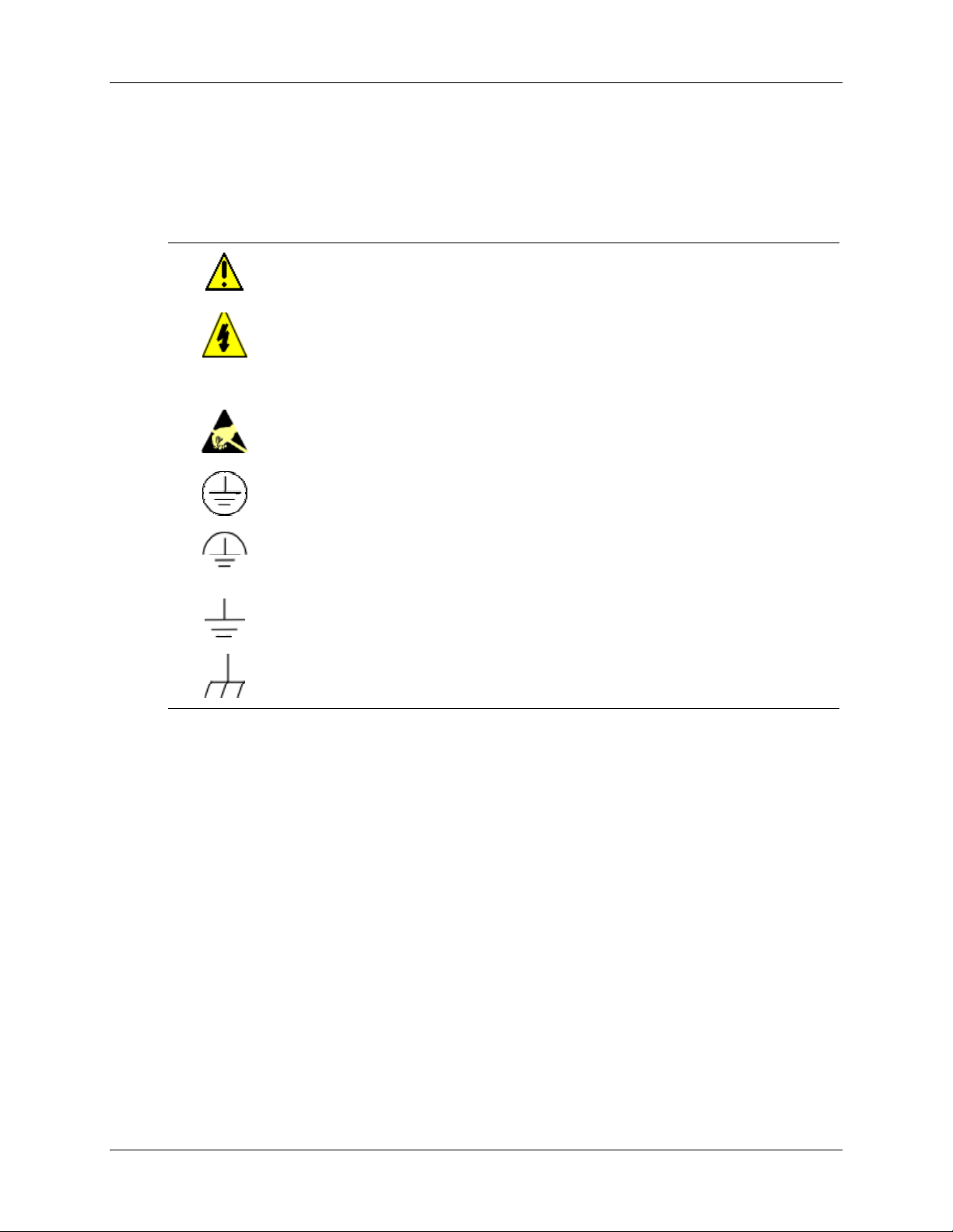
Symbol Definitions
The following table lists those symbols used in this document to denote certain conditions.
Symbol Definition
This CAUTION symbol on the equipment refers the user to the Product Manual for
additional information. This symbol appears next to required information in the
manual.
WARNING
PERSONAL INJURY: Risk of electrical shock. This symbol warns the user of a
potential shock hazard where HAZARDOUS LIVE voltages greater than 30 Vrms,
42.4 Vpeak, or 60 Vdc may be accessible. Failure to comply with these
instructions could result in death or serious injury.
ATTENTION, Electrostatic Discharge (ESD) hazards. Observe precautions for
handling electrostatic sensitive devices
Protective Earth (PE) terminal. Provided for connection of the protective earth (green
or green/yellow) supply system conductor.
Functional earth terminal. Used for non-safety purposes such as noise immunity
improvement. NOTE: This connection shall be bonded to protective earth at the
source of supply in accordance with national local electrical code requirements.
Earth Ground. Functional earth connection. NOTE: This connection shall be bonded
to Protective earth at the source of supply in accordance with national and local
electrical code requirements.
Chassis Ground. Identifies a connection to the chassis or frame of the equipment
shall be bonded to Protective Earth at the source of supply in accordance with
national and local electrical code requirements.
DR4300 Circular Chart Recorder Product Manual 4/00iv
Page 5

Contents
1. OVERVIEW...............................................................................................................1
1.1 Introduction...................................................................................................................................1
1.2 Model Number Breakdown...........................................................................................................4
1.3 About This Manual .......................................................................................................................9
2. INSTALLATION......................................................................................................11
2.1 Overview.....................................................................................................................................11
2.2 Mounting Considerations and Overall Dimensions....................................................................15
2.3 Mounting Methods......................................................................................................................16
2.3.1 Introduction....................................................................................................................16
2.3.2 Mounting Flush in Panel (New Panel Cutout)...............................................................17
2.3.3 Panel Mounting Recorder with NEMA4 or Heavy Duty door......................................18
2.3.4 Mounting on a 2-inch pipe.............................................................................................20
2.3.5 Mounting on Surface (of Panel or Wall) .......................................................................21
2.4 Wiring Prerequisites....................................................................................................................22
2.5 Input Wiring................................................................................................................................27
2.5.1 Power Wiring.................................................................................................................27
2.5.2 Analog Input Wiring......................................................................................................31
2.5.3 Digital Inputs (Optional)................................................................................................33
2.5.4 Communication (Optional)............................................................................................35
2.6 Output Wiring.............................................................................................................................37
2.6.1 Discrete Outputs.............................................................................................................37
2.6.2 Current Output...............................................................................................................41
2.6.3 Transmitter Power Out...................................................................................................43
3. CONFIGURATION, STARTUP, AND OPERATION OF BASIC RECORDER
WITHOUT DISPLAY...............................................................................................45
3.1 Overview.....................................................................................................................................45
3.2 Configuration (Recording Set Up)..............................................................................................46
3.2.1 Setting Configuration and Input Switches.....................................................................46
3.2.2 Setting SW6 Switch 2....................................................................................................64
3.3 Startup and Operation of Recorder without Display ..................................................................65
3.3.1 Overview........................................................................................................................65
3.3.2 Preparing the Recorder for Operation............................................................................66
3.3.3 Running the Optional Step Test.....................................................................................67
3.3.4 Startup............................................................................................................................69
4/00 DR4300 Circular Chart Recorder Product Manual v
Page 6

DR4300 Circular Chart Recorder
4. CONFIGURATION, STARTUP AND OPERATION OF RECORDER WITH
DISPLAY.................................................................................................................71
4.1 Overview.....................................................................................................................................71
4.2 Operator Interface on Recorder with Display and Keypad.........................................................72
4.3 Configuration (Recording and Output Set Up)...........................................................................74
4.3.1 Overview........................................................................................................................74
4.3.2 Configuration Prompts...................................................................................................75
4.3.3 How to Get Started.........................................................................................................77
4.3.4 Configuration Tips.........................................................................................................78
4.1.5 Switch Settings...............................................................................................................79
4.1.6 Configuration Procedure................................................................................................83
4.1.7 Input Parameters Set Up Group.....................................................................................85
4.1.8 Pen Parameters Set Up Group........................................................................................89
4.1.9 Chart Parameters Set Up Group.....................................................................................90
4.1.10 Totalizer Parameters Set Up Group...............................................................................91
4.1.11 Control Parameters Set Up Group.................................................................................94
4.1.12 Tuning Parameters Set Up Group................................................................................100
4.1.13 Setpoint Ramp/Program Set Up Group........................................................................104
4.1.14 Timer Set Up Group.....................................................................................................105
4.1.15 Alarms Set Up Group...................................................................................................106
4.1.16 Auxiliary Output Set Up Group...................................................................................109
4.1.17 Communication Set Up Group.....................................................................................111
4.1.18 Remote Switch (Digital Inputs) Set Up Group............................................................112
4.1.19 Display Parameter Set Up Group.................................................................................114
4.1.20 Lock Out Parameter Set Up Group..............................................................................115
4.1.21 Configuration Record Sheet.........................................................................................116
4.1.22 Limit Control Configuration........................................................................................118
4.4 Startup of Recorder with Display and Keypad.........................................................................119
4.4.1 Overview......................................................................................................................119
4.4.2 Preparing the Recorder for Startup..............................................................................120
4.4.3 Running the Optional Step Test...................................................................................121
4.4.4 Completing Preparation and Startup............................................................................123
4.5 Operation of Recorder with Display and Keypad.....................................................................128
4.5.1 Monitoring Your Recorder ..........................................................................................128
4.1.2 Operator Functions.......................................................................................................132
5. INPUT AND OUTPUT CALIBRATION FOR RECORDER WITH DISPLAY.........141
5.1 Overview...................................................................................................................................141
5.2 Input Calibration Minimum and Maximum Range Values.......................................................142
5.3 Input Calibration Preliminary Information...............................................................................144
5.4 Input Calibration Set Up and Wiring........................................................................................146
5.4.1 General Calibration Set Up..........................................................................................146
5.4.2 Thermocouple Inputs Using a Compensated Calibrator..............................................147
5.4.3 Thermocouple Inputs Using an Ice Bath or Ice Point Reference.................................148
5.4.4 RTD (Resistance Temperature Detector) Inputs .........................................................149
DR4300 Circular Chart Recorder Product Manual 4/00vi
Page 7

5.5 Input Calibration Procedure......................................................................................................151
5.6 Current Output Calibration.......................................................................................................153
6. ROUTINE MAINTENANCE...................................................................................157
6.1 Overview...................................................................................................................................157
6.2 Replacing the Chart...................................................................................................................158
6.3 Replacing the Ink Cartridge......................................................................................................159
6.4 Maximizing Pen Life ................................................................................................................160
7. TROUBLESHOOTING AND PEN ALIGNMENT OF BASIC RECORDER
WITHOUT DISPLAY.............................................................................................161
7.1 Overview...................................................................................................................................161
7.2 Observable Symptoms of Failure..............................................................................................163
7.3 Troubleshooting Procedures .....................................................................................................164
7.3.1 Overview......................................................................................................................164
7.3.2 Recorder Failure Troubleshooting...............................................................................165
7.3.3 Pen Trace Troubleshooting..........................................................................................166
7.3.4 Chart Rotation Troubleshooting ..................................................................................167
7.3.5 Troubleshooting Erratic Pen Movement......................................................................168
7.4 Alignment of Pen at Zero and 100 %........................................................................................169
8. TROUBLESHOOTING AND PEN ALIGNMENT OF RECORDER WITH
DISPLAY...............................................................................................................171
8.1 Overview...................................................................................................................................171
8.2 Troubleshooting Aids................................................................................................................173
8.3 Self Diagnostics........................................................................................................................174
8.3.1 Power up tests..............................................................................................................174
8.3.2 View Status of Tests ....................................................................................................175
8.3.3 Background Tests.........................................................................................................176
8.3.4 Error Messages.............................................................................................................176
8.4 Observable Symptoms of Failure..............................................................................................179
8.5 Troubleshooting Procedures .....................................................................................................180
8.5.1 Overview......................................................................................................................180
8.5.2 Recorder Failure Troubleshooting...............................................................................181
8.5.3 Pen Trace Troubleshooting..........................................................................................182
8.5.4 Chart Rotation Troubleshooting ..................................................................................183
8.5.5 Troubleshooting Erratic Pen Movement......................................................................184
8.5.6 Troubleshooting the Keypad and Display....................................................................184
8.5.7 Troubleshooting Relay Output.....................................................................................185
8.5.8 Troubleshooting External Alarm Function..................................................................186
8.5.9 Troubleshooting Remote Switch (Digital Input) Function..........................................186
8.5.10 Troubleshooting Modbus Communications.................................................................187
8.6 Alignment of Pen at Zero and Span..........................................................................................188
4/00 DR4300 Circular Chart Recorder Product Manual vii
Page 8

DR4300 Circular Chart Recorder
9. PARTS LIST.........................................................................................................191
9.1 Overview...................................................................................................................................191
9.2 Exploded Views........................................................................................................................192
A. ACCURACY..........................................................................................................199
A.1 Overview...................................................................................................................................199
A.2 Typical Reference Accuracy.....................................................................................................200
B. AVAILABLE 10-INCH CHARTS ...........................................................................203
B.1 Single Range Charts..................................................................................................................203
B.2 Dual Range Charts ....................................................................................................................209
C. SETPOINT RAMP/SOAK PROGRAMMING AND OPERATION..........................213
C.1 Overview...................................................................................................................................213
C.2 Program Contents..................................................................................................................214
C.3 Drawing a Ramp/Soak Profile ..................................................................................................216
C.4 Setpoint Program Prompt Hierarchy.........................................................................................220
C.5 Run/Monitor the Program.........................................................................................................223
D. USING ACCUTUNE II...........................................................................................227
D.1 Overview...................................................................................................................................227
D.2 Starting and Stopping Tuning with Accutune II.......................................................................228
D.3 Using Accutune with Duplex (Heat/Cool) Control ..................................................................229
E. FOREIGN LANGUAGE SAFETY INSTRUCTIONS..............................................231
F. HONEYWELL SERVICE CENTERS ....................................................................243
DR4300 Circular Chart Recorder Product Manual 4/00viii
Page 9

Tables
Table 2-1 Operating Limits and Condensed Specifications........................................................................................12
Table 2-2 Mounting Flush in a New Panel Cutout......................................................................................................17
Table 2-3 Procedure for Mounting Recorder with NEMA4 or Heavy Duty Door......................................................18
Table 2-4 Pipe Mounting Procedure...........................................................................................................................20
Table 2-5 Mounting Flush on a Surface (of Panel or Wall)........................................................................................21
Table 2-6 Wiring Bundling Categories.......................................................................................................................26
Table 2-7 Wiring Illustrations ....................................................................................................................................26
Table 2-8 Procedure for Power Wiring Models..........................................................................................................28
Table 2-9 Analog Input Wiring..................................................................................................................................31
Table 2-10 Digital Input Wiring.................................................................................................................................33
Table 2-11 Communication Wiring............................................................................................................................35
Table 2-12 Output Terminal Use for Output Algorithm and Option Combinations...................................................37
Table 2-13 Relay Output Wiring - 1 or 2 Pen Models................................................................................................38
Table 2-14 Current Output Wiring.............................................................................................................................41
Table 2-15 Transmitter Power Out Wiring.................................................................................................................43
Table 3-1 Procedure for Configuring Model without Display....................................................................................46
Table 3-2 Configuration and Input Switch Settings for Models without Display.......................................................49
Table 3-3 Preparing the Recorder for Operation........................................................................................................66
Table 3-4 Procedure for Running the Step Test..........................................................................................................67
Table 3-5 Startup Procedure.......................................................................................................................................69
Table 4-1 Key Functions ............................................................................................................................................73
Table 4-2 Configuration Tips.....................................................................................................................................78
Table 4-3 SW6 Input Switch Settings for Models Having Display and Keypad .......................................................80
Table 4-4 Configuration Procedure............................................................................................................................83
Table 4-5 Input Parameter Definitions .......................................................................................................................85
Table 4-6 Pen Parameter Definitions..........................................................................................................................89
Table 4-7 Chart Parameter Definitions.......................................................................................................................90
Table 4-8 Totalizer Function Definitions...................................................................................................................91
Table 4-9 Control Parameter Definitions....................................................................................................................94
Table 4-10 Tuning Parameter Definitions ................................................................................................................101
Table 4-11 Setpoint Ramp Parameter Definitions....................................................................................................104
Table 4-12 Timer Parameter Definitions..................................................................................................................105
Table 4-13 Alarm Parameter Definitions..................................................................................................................106
Table 4-14 Auxiliary Output Parameter Definitions.................................................................................................109
Table 4-15 Communication Parameter Definitions..................................................................................................111
Table 4-16 Remote Switch Parameter Definitions....................................................................................................113
Table 4-17 Display Parameter Definitions................................................................................................................114
Table 4-18 Lockout Parameter Definitions...............................................................................................................115
Table 4-19 Limit Control Parameter Definitions......................................................................................................118
Table 4-20 Preparing the Recorder for Operation............................................................................... .....................120
Table 4-21 Procedure for Running the Step Test......................................................................................................121
Table 4-22 Procedure for Setting Chart Time and Applying Power.........................................................................123
Table 4-23 Power-Up Diagnostic Tests....................................................................................................................124
Table 4-24 Procedure for Testing the Displays and Keys.........................................................................................125
Table 4-25 Procedure for Starting the Recorder.......................................................................................................126
Table 4-26 Meaning of Indicators............................................................................................................................129
Table 4-27 Lower Display Operating Parameter Labels...........................................................................................130
Table 4-28 Error Messages.......................................................................................................................................131
Table 4-29 Procedure for Selecting Automatic or Manual Mode .............................................................................133
Table 4-30 Procedure for Changing the Control Setpoints.......................................................................................134
Table 4-31 Procedure for Displaying or Changing the Alarm Setpoints ..................................................................135
Table 4-32 Procedure for Selecting Factory or Field Calibration Values.................................................................136
4/00 DR4300 Circular Chart Recorder Product Manual ix
Page 10

DR4300 Circular Chart Recorder
Table 4-33 Procedure for Resetting Totalizer...........................................................................................................137
Table 4-34 Procedure for Starting Timer..................................................................................................................138
Table 4-35 Procedure for Resetting Limit Controller...............................................................................................139
Table 5-1 Voltage and Resistance Equivalents for 0 % and 100 % Range Values...................................................143
Table 5-2 Equipment Needed for Calibration...........................................................................................................144
Table 5-3 Disconnect the Field Wiring.....................................................................................................................145
Table 5-4 General Calibration Set Up Procedure.....................................................................................................146
Table 5-5 Set Up Wiring Procedure for Thermocouple Inputs Using a Compensated Calibrator...........................147
Table 5-6 Set Up Wiring Procedure for Thermocouple Inputs Using an Ice Bath...................................................148
Table 5-7 Set Up Wiring Procedure for Calibrating RTD Inputs.............................................................................149
Table 5-8 Set Up Wiring Procedure for Calibrating Millivolts, Volts, and Milliamps Inputs..................................150
Table 5-9 Input Calibration Procedure Sequence.....................................................................................................151
Table 5-10 Set Up Wiring Procedure for Current Proportional Output....................................................................153
Table 5-11 Procedure for Calibrating Current Output..............................................................................................154
Table 6-1 Procedure for Replacing the Chart...........................................................................................................158
Table 6-2 Procedure for Replacing the Ink Cartridge...............................................................................................159
Table 6-3 Maximizing Pen Life................................................................................................................................160
Table 7-1 Observable Symptoms of Failure.............................................................................................................163
Table 7-2 Troubleshooting Recorder Failure Symptoms..........................................................................................165
Table 7-3 Troubleshooting Pen Trace Failure Symptoms ........................................................................................166
Table 7-4 Troubleshooting Chart Rotation Failure Symptoms.................................................................................167
Table 7-5 Troubleshooting Erratic Pen Movement Symptoms.................................................................................168
Table 7-6 Procedure for Pen Alignment...................................................................................................................169
Table 8-1 Procedure for Identifying the Software Version.......................................................................................173
Table 8-2 Power-Up Diagnostic Tests......................................................................................................................174
Table 8-3 Procedure for Displaying the Results of Self-Diagnostics........................................................................175
Table 8-4 Error Messages.........................................................................................................................................177
Table 8-5 Observable Symptoms of Failure.............................................................................................................179
Table 8-6 Troubleshooting Recorder Failure Symptoms..........................................................................................181
Table 8-7 Troubleshooting Pen Trace Failure Symptoms ........................................................................................182
Table 8-8 Troubleshooting Chart Rotation Failure Symptoms.................................................................................183
Table 8-9 Troubleshooting Erratic Pen Movement Symptoms.................................................................................184
Table 8-10 Troubleshooting Keypad and/or Display Failure Symptoms..................................................................184
Table 8-11 Troubleshooting Relay Output Failure Symptoms .................................................................................185
Table 8-12 Troubleshooting External Alarm Function Failure Symptoms...............................................................186
Table 8-13 Troubleshooting Remote Switch (Digital Input) Function Failure Symptoms.......................................186
Table 8-14 Troubleshooting Modbus Communications............................................................................................187
Table 8-15 Procedure for Aligning Pen at Zero and Span........................................................................................188
Table 9-1 Door Assembly Parts................................................................................................. ...............................192
Table 9-2 Chart Plate Assembly Parts......................................................................................................................193
Table 9-3 Basic Recorder Parts................................................................................................................................195
Table A-1 Typical Reference Accuracy....................................................................................................................200
Table B-1 10-inch Single Range Chart Part Numbers..............................................................................................203
Table B-2 10-inch Dual Range Chart Part Numbers ............................................................................... .................209
Table C-1 Prompt Hierarchy and Available Selections............................................................................................220
Table C-2 Run/Monitor Functions............................................................................................................................223
Table D-1 Procedure for Starting Accutune II..........................................................................................................228
Table D-2 Procedure for Using Accutune for Duplex Control.................................................................................229
DR4300 Circular Chart Recorder Product Manual 4/00x
Page 11

Figures
Figure 1-1 Guide to Manual’s Organization...............................................................................................................10
Figure 2-1 Overall Dimensions...................................................................................................................................15
Figure 2-2 Plug Locations...........................................................................................................................................16
Figure 2-3 Mounting Flush in a New Panel Cutout (Rear View)................................................................................17
Figure 2-4 Panel Mounting Recorder with NEMA4 or Heavy Duty Door.................................................................19
Figure 2-5 Pipe Mounting Brackets............................................................................................................................20
Figure 2-6 Mounting Flush on a Surface of Panel or Wall (Rear View).....................................................................22
Figure 2-7 Recommended Wiring Routing - Models Without CE Mark....................................................................24
Figure 2-8 Recommended Wiring Routing - Models With CE Mark.........................................................................25
Figure 2-9 Power Wiring – Models Without CE Mark...............................................................................................29
Figure 2-10 Power Wiring – Models With CE Mark..................................................................................................30
Figure 2-11 Analog Input Wiring...............................................................................................................................32
Figure 2-12 Digital Input Wiring................................................................................................................................34
Figure 2-13 Communication Wiring...........................................................................................................................36
Figure 2-14 Relay Output Wiring...............................................................................................................................39
Figure 2-15 Open Collector Output Wiring................................................................................................................40
Figure 2-16 Current Output Wiring............................................................................................................................42
Figure 2-17 Transmitter Power Out Wiring................................................................................................................44
Figure 3-1 Location of Configuration and Input Switches..........................................................................................47
Figure 3-2 Sample Chart for Single Pen Recorder...................................................................................................... 48
Figure 3-3 Basic Chart Plate Components ....................................................................................... ...........................66
Figure 3-4 Typical Step Test Chart Patterns...............................................................................................................68
Figure 3-5 Setting Chart Time to Time Index.............................................................................................................69
Figure 4-1 Operator Interface.....................................................................................................................................72
Figure 4-2 Prompt Hierarchy......................................................................................................................................75
Figure 4-3 Location of Switches and Relays..............................................................................................................82
Figure 4-4 Basic Chart Plate Components ....................................................................................... .........................120
Figure 4-5 Typical Step Test Chart Patterns.............................................................................................................122
Figure 4-6 Setting Chart Time to Time Index...........................................................................................................123
Figure 4-7 Operator Interface...................................................................................................................................128
Figure 5-1 Location of the Input Connections on the Input Boards..........................................................................145
Figure 5-2 Calibration Set Up Diagram for Thermocouple Inputs Using a Compensated Calibrator......................147
Figure 5-3 Calibration Set Up Diagram for Thermocouple Inputs Using an Ice Bath ..............................................148
Figure 5-4 Calibration Set Up Diagram for RTD Inputs ..........................................................................................149
Figure 5-5 Calibration Set Up Diagram for Millivolts, Volts, and Milliamps Inputs...............................................150
Figure 5-6 Test Equipment Connections for Calibrating Current Output.................................................................153
Figure 6-1 Replacing the Chart and Ink Cartridge....................................................................................................158
Figure 9-1 Door Assembly........................................................................................................................................192
Figure 9-2 Chart Plate Assembly..............................................................................................................................193
Figure 9-3 Recorder Components.............................................................................................................................194
Figure 9-4 DR4300 Recorder (CE Mark) – Internal Cabling Diagram....................................................................196
Figure 9-5 DR4300 Recorder (Non-CE Mark) – Internal Cabling Diagram ............................................................197
Figure C-1 Ramp/Soak Profile Example...................................................................................................................216
4/00 DR4300 Circular Chart Recorder Product Manual xi
Page 12

DR4300 Circular Chart Recorder
DR4300 Circular Chart Recorder Product Manual 4/00xii
Page 13

1.1 Introduction
Function
The DR4300 recorder is a one or two pen microprocessor-based circular chart recorder. The basic DR4301
(one pen) and DR4302 (two pen) recorders provide reliable, convenient pen-drawn analog traces on
preprinted 10 inch (250 mm) charts. Both the chart and the pens are driven by stepper motors controlled by
the microprocessor. Chart speed and range are configurable. The basic recorder is also available in CE
models DR4321 (one pen) and DR4322 (two pen).
In addition to generating pen-drawn chart traces, the DR4311 (one pen) and DR4312 (two pen) models
include a display and keypad. This option lets you display the real time value of the process variable for
each pen channel, as well as other values. The recorder with display and keypad is also available in CE
models DR4331 (one pen) and DR4332 (two pen).
Each pen channel has its own printed circuit assembly (PCA), allowing the channels to operate
independently.
Overview
1. Overview
CE conformity (Europe)
Indicated models of this product are in conformity with the protection requirements of the following
European Council Directives: 73/23/EEC, the Low Voltage Directive, and 89/336/EEC, the EMC
Directive. Conformity of this product with any other “CE Mark” Directive(s) shall not be assumed.
Deviation from the installation conditions specified in this manual, and the special conditions for CE
conformity in Section 2 of this manual, may invalidate this product’s conformity with the Low Voltage and
EMC Directives.
Analog inputs
The input for each pen channel can be one of any standard electrical signal: milliamp, millivolt, voltage,
RTD, or thermocouple. The input type and range are configurable. In the models having display and keypad
the range can be expanded and compressed to meet specific measurement needs. The display and keypad
also permit entry of input bias and filter values. (The input filter for the models without a display is fixed at
one second; their bias is zero.)
Digital inputs
Two digital inputs for each pen channel are available as an option. These inputs can be used to trigger the
switchover to a second control setpoint or a pre-configured constant output if an external event causes
contact closure (sets the digital input to ON). In addition, the digital inputs can be used to remotely reset the
optional totalizer or limit controller.
4/00 DR4300 Circular Chart Recorder Product Manual 1
Page 14

DR4300 Circular Chart Recorder
Communications
The Modbus communication option permits configuration of the unit and monitoring of process variables
over a standard multi-drop serial communications link.
Relay outputs for control and alarms
The models with display and keypad are available with output relays, two for each pen channel. These
relays can be wired for Normally Open (NO) and Normally Closed (NC) terminals. ON-OFF control can be
performed using one relay (relay simplex control) or two relays (relay duplex control).
Any relay not used for control is available for alarming. Two alarm setpoints can be configured for each
alarm relay. An adjustable hysteresis of 0.0 % to 100.0 % is configurable for the alarm setpoint.
Analog output for control or retransmission
Depending on the model ordered, a 4 to 20 mA current output may be available for control or
retransmission of a process variable (“auxiliary output”).
Failsafe operation
The control function can operate in automatic or manual mode. In automatic the control function works to
maintain the process variable at the setpoint entered locally by the operator. During configuration a
“failsafe” value can be specified. This value is used as the output at power up and in case of input failure
during automatic operation. (When the unit goes to failsafe, the control function goes to manual mode.)
In manual mode the operator enters the output locally. If the recorder has gone to failsafe operation, the
operator will be able to change the output value from the failsafe value specified during configuration.
Timer and totalizer options
The recorder is available with timer and totalizer options. The timer can be started locally, remotely, or by
an alarm. The unit can be configured to display elapsed time or time remaining. At the end of the timeout
period Relay 2 is energized, and remains energized until the timer is reset. The totalizer can be reset locally
or remotely; its displayed value can be scaled.
Setpoint Programming Option
The recorder is available with a Setpoint Program option. This feature allows configuration of up to four
setpoint programs using a total of twenty-four ramp and soak segments. A setpoint and time is configured
for each segment. The program can be set up to include guaranteed soak segments. A plus/minus deviation
is configured for all soak segments. Whenever the plus/minus deviation is exceeded, soak timing is frozen.
Display and keypad
In addition to process variables, the display can show output, setpoint, and deviation real time values if the
recorder is equipped with optional outputs. The upper display uses four characters to display the input
value. The lower display shows other parameters using a two- or three-character label and four- or threedigit values. In addition, status and error messages flash on the lower display when necessary.
DR4300 Circular Chart Recorder Product Manual 4/002
Page 15

The six keys are used to select the real time value to be displayed, and to select set up parameters and their
values during configuration. The display and keypad are behind the door, protecting them from dirt.
A supplementary external keypad is also available.
For more information about the operator interface on models having a display and keypad, see Subsection
4.2.
Configuration
The models without a display are configured with two switchbanks: one for configuration, the other for
input definition. Configuration is a simple matter of consulting a table in this manual; selecting the
appropriate combination of range, chart speed, engineering unit, and input type; then setting the switches as
shown in the table.
The display and keypad are used to configure models with these options. When the unit is in configuration
mode, set up parameters are displayed, and grouped by function. Designate site-specific values by selecting
them from a list of choices, or entering them as numeric values. The operator can be locked out from
making configuration changes.
The models with display also use a switchbank to define the type of input to be expected by the hardware.
Input parameters used by the software are configured using the display and keypad.
Overview
Self-diagnostics
All DR4300 recorders run self-diagnostics at power up and in the background during normal operation.
Problems are reported by error messages on the display when present. An LED in the models without a
display lights if the unit fails a self-diagnostic.
Construction
All DR4300 recorders are housed in a rugged molded case which can be panel-, pipe- or surface-mounted.
An acrylic-windowed, gasketed door protects internal components from harsh environments while allowing
easy access to the chart.
4/00 DR4300 Circular Chart Recorder Product Manual 3
Page 16

DR4300 Circular Chart Recorder
1.2 Model Number Breakdown
Introduction
The model number breakdown is presented in the tables that follow. Note that not all options are available
with all recorders. Check the “Availability” column for each model. A star () in the Availability column
means unrestricted availability of the feature for that model. N/A indicates the feature is not available for
that model. A letter in the Availability column denotes restricted availability. The meaning of each letter is
provided at the bottom of this page.
The Notes referred to in the tables are also at the end of this subsection.
Model number format
The basic model number consists of a key number. Appended to this key number are characters that identify
the features in various categories. The meaning of the characters in each category is presented in a table
identified below.
Key Number Table I Table II Table III Table IV Table V Table VI
DR43_ _ - _ _ _ _ - _ _ _ _ _ - _ _ _ _ - _ _ _ _ - _ _ - 000
Key numbers
The base model numbers for the DR4300 Circular Chart Recorder are:
One Pen Recorder (Basic Recorder Without Display) DR4301
Two Pen Recorder (Basic Recorder Without Display) DR4302
One Pen Recorder (With Display) DR4311
Two Pen Recorder (With Display) DR4312
One Pen Recorder (Basic Recorder Without Display, With CE Mark) DR4321
Two Pen Recorder (Basic Recorder Without Display, With CE Mark) DR4322
One Pen Recorder (With Display, With CE Mark) DR4331
Two Pen Recorder (With Display, With CE Mark) DR4332
Restricted availability designations
d = Not available with Table I selection XX0X.
e = Not available with Table I selection XXX0.
f = Not available with Table I selection 0XXX.
g = Not available with Table I selection 0000.
h = Not available with Table I selections FXXX, XFXX, GXXX, XGXX.
j = Not available with Table I selection 0XXX.
k = Not available with Table I selection X0XX.
m = Not available with Table I selections 2XXX, 3XXX, 4XXX, 5XXX, AXXX, XXX0.
n = Not available with Table II selection SXXXX.
p = Not available with Table II selections RXXXX, SXXXX.
q = Not available with Table II selections GXXXX, BXXXX, HXXXX, CXXXX, KXXXX, LXXXX.
DR4300 Circular Chart Recorder Product Manual 4/004
Page 17
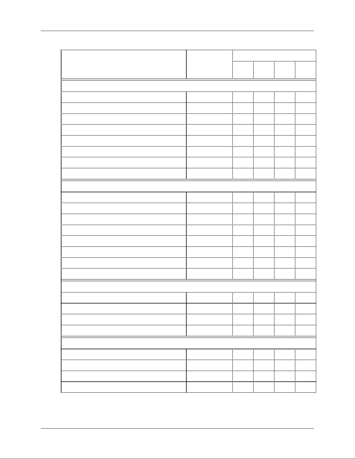
Model Number Table I - OUTPUT
Description Model No. Availability
Overview
4301
4321
Pen One
None 0 _ _ _
2 Outputs (Alarm/On-Off Control) 2 _ _ _ N/A N/A d d
1 PID Control with Accutune II (see Note 1) 3 _ _ _ N/A N/A d d
1 PID Control/Setpoint Program/Timer (see Not e 1) 4 _ _ _ N/A N/A d d
2 Outputs (Alarm 1 and Timer) 5 _ _ _ N/A N/A d d
4 to 20 mA Retransmission Output (see Note 4) A _ _ _ N/A N/A d d
FM Approved Limit Control F _ _ _ N/A N/A d d
FM Approved Limt Control/Timer Output G _ _ _ N/A N/A d d
Pen Two
None _ 0 _ _
2 Outputs (Alarm/On-Off Control) _ 2 _ _ N/A N/A N/A e
1 PID Control with Accutune II (see Note 1) _3 _ _ N/A N/A N/A e
1 PID Control/Setpoint Program/Timer (see Not e 1) _ 4 _ _ N/A N/A N/A e
4302
4322
4311
4331
4312
4332
2 Outputs (Alarm 1 and Timer) _ 5 _ _ N/A N/A N/A e
4 to 20 mA Retransmission Output (see Note 4) _ A _ _ N/A N/A N/A e
FM Approved Limit Control _ F _ _ N/A N/A N/A m
FM Approved Limt Control/Timer Output _ G _ _ N/A N/A N/A m
Output Type Pen 1
None _ _ 0 _
Electromechanical Relay _ _ E _ N/A N/A j j
Solid State Relay _ _ S _ N/A N/A j j
Open Collector _ _ T _ N/A N/A j j
Output Type Pen 2
None _ _ _ 0
Electromechanical Relay _ _ _ E N/A N/A N/A k
Solid State Relay _ _ _ S N/A N/A N/A k
Open Collector _ _ _ T N/A N/A N/A k
4/00 DR4300 Circular Chart Recorder Product Manual 5
Page 18
DR4300 Circular Chart Recorder
Description Model No. Availability
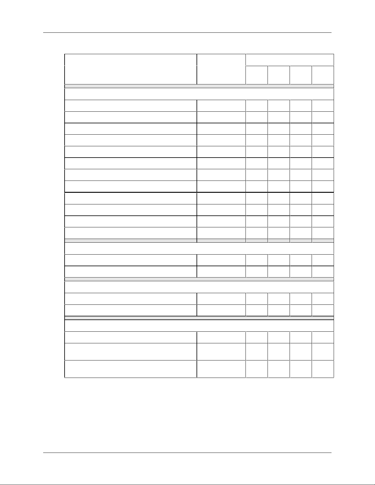
Model Number Table II - INSTRUMENT OPTIONS
4301
4321
4302
4322
4311
4331
4312
4332
Door Options
Gray Door G _ _ _ _
Blue Door B _ _ _ _
Gray Door with External Keypad H _ _ _ _ N/A N/A
Blue Door with External Keypad C _ _ _ _ N/A N/A
Black Door K _ _ _ _
Black Door with External Keypad L _ _ _ _ N/A N/A
SST Door R _ _ _ _
NEMA 4 SST Door S _ _ _ _
Standard Latch _ 0 _ _ _ nnnn
Keyed Latch _ A _ _ _
Keyed Latch/Chart Plate Seal _ B _ _ _ qqqq
Door Lock _ K _ _ _ pppp
Instrument Power/Transmitter Power
Universal Recorder Power _ _ 1 _ _
Universal Power +24 Vdc Transmitter Power _ _ 3 _ _
Communications
None _ _ _ 0 _
RS485 Modbus RTU Communication (see Note 5) _ _ _ C _
Product Configuration
Standard _ _ _ _ 0
Configuration for Non-Standard Range Settings
(see Note 6)
Configuration for Customer’s Specific Data
(see Note 6)
_ _ _ _ 1
_ _ _ _ 2 N/A N/A
N/A N/A
DR4300 Circular Chart Recorder Product Manual 4/006
Page 19
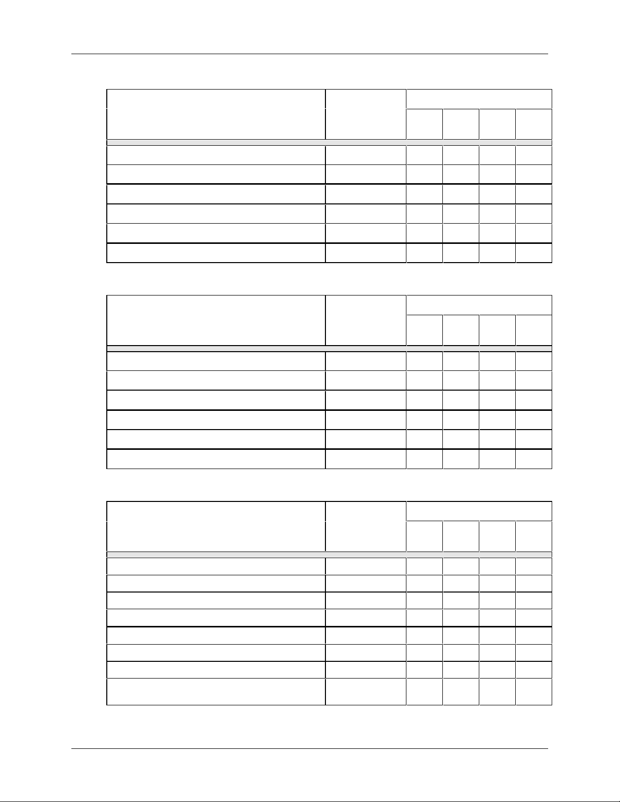
Model Number Table III - PEN 1 OPTIONS
Description Model No. Availability
Overview
4301
4321
No Digital Inputs 0 _ _ _
Digital Inputs (See Note 3) D _ _ _ N/A N/A f g
None _ 0 _ _
No Totalizer Function _ _ 0 _
Totalizer _ _ T _ N/A N/A h h
Future _ _ _ 0
4302
4322
4311
4331
4312
4332
Model Number Table IV - PEN 2 OPTIONS
Description Model No. Availability
4301
4321
No Digital Inputs 0 _ _ _
Digital Inputs (See Note 3) D _ _ _ N/A N/A N/A g
None _ 0 _ _
4302
4322
4311
4331
4312
4332
No Totalizer Function _ _ 0 _
Totalizer _ _ T _ N/A N/A N/A h
Future _ _ _ 0
Model Number Table V - APPROVALS/CERTIFICATES
Description Model No. Availability
4301
4321
No Approvals 0 _
UL Listing U _ nnnn
CSA Certification C _ nnnn
UL and CSA Approved B _ nnnn
No Certificate _ 0
Certificate of Conformance (F3391) _ 1
Certificate of Calibration (F3399) (See Note 2) _ 2
Certificate of Conformance and Calibration
(See Note 2)
_ 3
4302
4322
4311
4331
4312
4332
4/00 DR4300 Circular Chart Recorder Product Manual 7
Page 20

DR4300 Circular Chart Recorder
NOTE 1: PID control o ptions include current output plus two discrete outputs for alarms. If ON-OFF or
time-proportioned simplex control is used, only one discrete output is available for an alarm.
Time-proportioned duplex control requires the use of both outputs and therefore no relay outputs
are available for alarms on that pen channel. Accutune II tuning is a standard feature with PID
control options.
NOTE 2: Customer must supply the input actuation and range information for each input in the Free Form
section of the order to have the unit supplied with a Certificate of Calibration.
NOTE 3: Digital Inputs are only available when ordering outputs in Table I.
NOTE 4: 4 to 20 mA Retransmission Output includes two outputs per pen for alarms. You must specify
the type of alarm outputs required (i.e., Relay, SS Relay, Open Collector Outputs).
NOTE 5: On key numbers DR4301, DR4302, DR4321, and DR4322 the communication address is fixed;
the display assembly is required to change it. Only one DR4301 or DR4321 instrument, or only
one pen of a DR4302 or DR4322 can exist on the network, otherwise communication conflicts
will exist. Pen 1 is the default when communications is specified on these models.
NOTE 6: Recorder is supplied with one box of 30755820-001, 0 to 100 Even "starter" charts. For special
range configuration on the DR4301, DR4302, DR4321, or DR4322 Recorder, provide the Input
Type, Chart Range, Chart Speed, °C or °F, Engineering Units, Linear or Non-Linear Chart Type
when ordering.
For example: Pen 1: "J" Thermocouple, 0-375 °F, 7-Day Linear Chart
Pen 2: 4-20 mA, 0-1000, 7-Day Linear Chart
For configuration on Models DR4311, DR4312, DR4331, and DR4332, the customer must
supply completed "Configuration Worksheets" with order for units to be Factory configured.
DR4300 Circular Chart Recorder Product Manual 4/008
Page 21

1.3 About This Manual
All models described
This manual contains instructions for installation, set up, startup, operation, troubleshooting, and repair of
all recorder models listed in Subsection 1.2. The models fall into two broad categories:
• basic version without display: DR4301, DR4302, DR4321, and DR4322
• enhanced version with display: DR4311, DR4312, DR4331, and DR4332
Some sections in the manual apply to all models, while others contain information specific to one of these
two categories. Unless a section’s title refers to recorders “without display” or “with display”, the
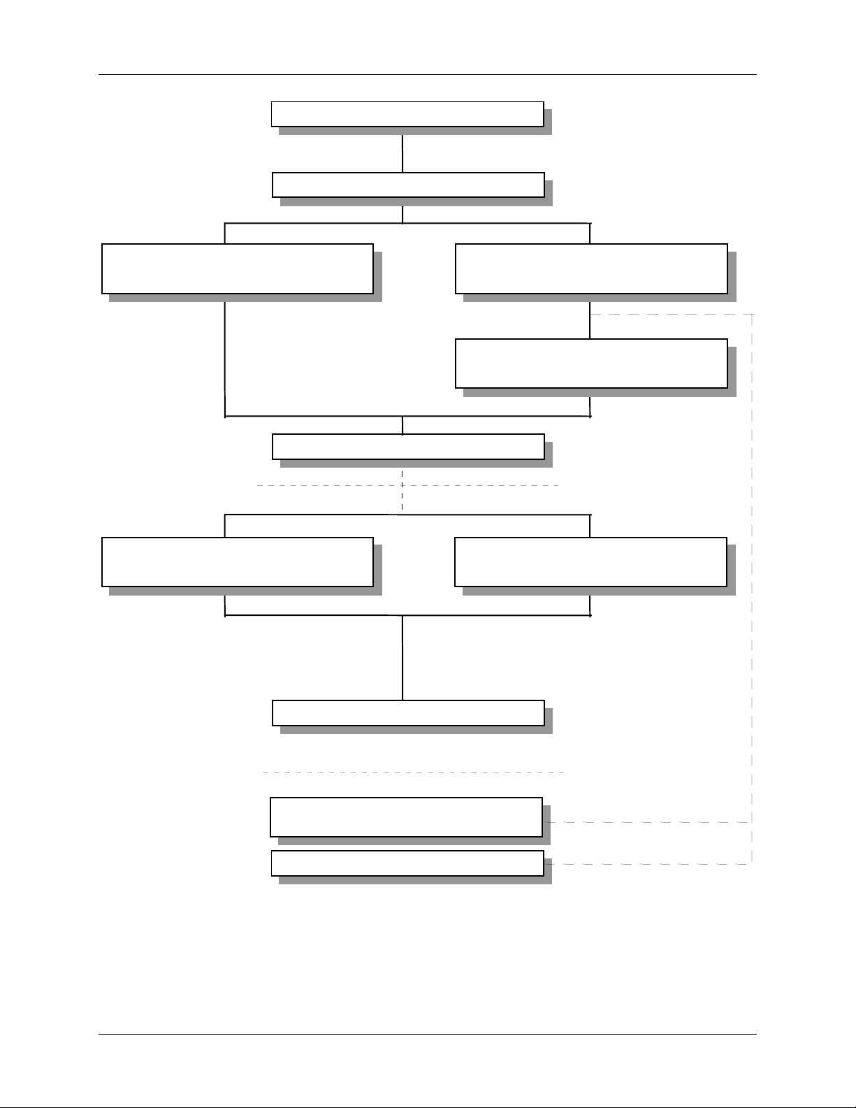
information in the section applies to all models. To see which sections apply to your recorder, see Figure
1-1.
Overview
4/00 DR4300 Circular Chart Recorder Product Manual 9
Page 22
DR4300 Circular Chart Recorder
SECTION
3 - Configuration, Startup, and
Operation of Recorder
Trouble?
without
SECTION
Display
SECTION
SECTION
1 - Overview
2 - Installation
SECTION
Operation of Recorder
Calibration for Recorder
6 - Routine Maintenance
4 - Configuration, Startup, and
Display
with
SECTION
5 - Input and Output
Display
with
SECTION
7 - Troubleshooting and Pen
Alignment of Recorder
Options
SECTION
without
APPENDIX C -
Display
SECTION
9 - Parts List
Setpoint Ramp/Soak
Alignment of Recorder
Programming and Operation
APPENDIX D -
Using Accutune II
Figure 1-1 Guide to Manual’s Organization
8 - Troubleshooting and Pen
Display
with
24209
DR4300 Circular Chart Recorder Product Manual 4/0010
Page 23

2.1 Overview
Introduction
Installation of the DR4300 recorder consists of mounting and wiring the recorder according to the
instructions given in this section.
Read the pre-installation information below, check the model number interpretation in Section 1, and
become familiar with your model selections, then proceed with installation.
What’s in this section?
The following is a list of topics in this section.
2.1 Overview 11
2.2 Mounting Considerations and Overall Dimensions 15
2.3 Mounting Methods 16
2.4 Wiring Prerequisites 22
2.5 Input Wiring 27
2.6 Output Wiring 37
Installation
2. Installation
Topic See Page
Pre-installation information
If the recorder has not been removed from its shipping carton, inspect the carton for damage and remove the
recorder. Inspect the unit for any obvious shipping damage and report any damage due to transit to the
carrier.
• Make sure a bag c ontaining mounting hardware is included in the carton with the recorder.
• Check that the model number shown on the chart plate agrees with what you have ordered.
3/00 DR4300 Circular Chart Recorder Product Manual 11
Page 24
DR4300 Circular Chart Recorder
Operating limits
We recommend that you review and adhere to the operating limits listed in Table 2-1 when you install your
recorder.
Table 2-1 Operating Limits and Condensed Specifications
Condition Specifications
Accuracy See Appendix A
Ambient Temperature 0 °C to 55 °C [32 °F to 131 °F]
Relative Humidity 5 % to 90 % RH at 40 °C [104 °F]
Vibration
Frequency
Acceleration
Mechanical Shock
Acceleration
Duration
Mounting Position from
Vertical
Tilted Forward
Tilted Backward
Tilted to side (±)
0 to 200 Hz
0.5 g
5 g
30 ms
5°
90°
20°
Power
Voltage (ac/dc)
Frequency (Hz)
Power Consumption 20 Watts maximum
Type of Actuations Thermocouple: B, E, E (low), J, J (low), K, K (low), Ni-Ni Moly, Nicrosil-Nisil, R, S,
Minimum Input Span Range is fully configurable within span limitation of the sensing element.
Input Impedance mA dc: 250 ohms
Span Step Response Time 7 seconds maximum
Reproducibility 0.1 percent of span
100 Vac to 240 Vac
or
20 Vac/Vdc to 27 Vac/Vdc
49 Hz to 61 Hz
T, T (low), W5 W26
RTD: Platinum 100 ohms*, 100 ohms (low)*, 100 ohms**
Linear: 4-20 mA dc, 0-20 mA dc, 0-10 mV dc, 0-100 mV dc, 0-200 mV dc,
0-1 Vdc, 0-2 Vdc, 0-5 Vdc, 0-10 Vdc, 1-5 Vdc, 2-10 Vdc
Digital: +24 Vdc source for external dry contacts or isolated solid state contacts
*IEC Alpha = 0.00385
**Alpha = 0.00391
Vdc: 200K ohms
RTD: 13.3 K ohms
All others: 10 Megohms
Sampling Rate Input sampled 3 times per second
DR4300 Circular Chart Recorder Product Manual 3/0012
Page 25
Installation
Condition Specifications
Input Filter W ithout Display: Analog with time constant of 3 seconds and digital with time
constant of 1 second.
With Display: Analog with time constant of 3 seconds and digital adjustable 0
seconds to 120 seconds.
Case Molded, foamed-Noryl with gasketed door to meet NEMA 3 enclosure
requirements.
Pen Disposable fiber-tip ink cartridge, line length per cartridge more than 305 m
[1000 ft]
One Pen: Purple
Two Pen: Purple (pen 1) and red (pen 2)
NOTE: Only pen 1 (purple) is referenced to the chart time line.
Chart 262 mm [10.32-inch] diameter chart with standard preprinted markings and a
calibrated width of 100 mm [4 inches].
Wiring Connections Screw terminals (2 piece)
Color Case: Black
Door: Standard—Gray; Optional—Carribean blue or black
Weight 5.4 kg [12 lbs]
Mounting Panel-, pipe- or surface-mounted
Installation Category
(Overvoltage Category)
Pollution Degree Pollution Degree 2: Normally Non-conductive Pollution with Occasional
EMC Classification Group 1, Class A: ISM Equipment (EN55011, emissions), Industrial Equipment
Dielectric Insulation AC Main to Inputs/Outputs 250 Vac
Category II: Energy-consuming Equipment Supplied from the Fixed Installation,
Local Level Appliances, and Industrial Control Equipment (EN61010-1).
Conductivity Caused by Condensation (Ref. IEC 664-1).
(EN50082-2, Immunity).
Input to Input 250 Vac
Input to Output 250 Vac
(except Digital Input to Current Output)
AC Main to Transmitter Power 250 Vac
Options
Current Output (Isolated) Range can be set anywhere between 4 mA and 21 mA, and as direct or reverse
action.
Resolution: 11 bits for 4 mA to 21 mA
Accuracy: 0.5 % full scale
Temperature Stability: 0.1 % F.S./°C
Load Resistance: 0 ohms to 600 ohms
Electromechanical Relay
Output
SPDT contacts. Internally socketed.
Resistive Load: 5 A @ 120 Vac or 2.5 A @ 240 Vac or 30 Vdc.
Inductive Load: 50 VA @ 120 Vac or 240 Vac.
Motor: 1/6 H.P.
3/00 DR4300 Circular Chart Recorder Product Manual 13
Page 26

DR4300 Circular Chart Recorder
Condition Specifications
Solid State Relay Output SPST solid state contacts consisting of a triac NO output.
Internally socketed.
Resistive Load: 1.0 A @ 25 °C for 120 Vac or 240 Vac.
0.5 A @ 55 °C for 120 Vac or 240 Vac.
Inductive Load: 50 VA @ 120 Vac or 240 Vac.
Open Collector Output Maximum Sink Current: 20 mA
Internally powered @ 30 Vdc
Opto-isolated from all other circuits except current output, but not from each other.
Socketed jumper assembly replaces relay.
Modbus Communication Baud Rate: 19,200 maximum, configurable for models with display;
fixed at 9,600 for models without display
Protocol: Modbus
Length of Link: 1,219 m [4,000 ft] maximum
Link Characteristics: Two-wire, multidrop
Digital Inputs
(Supply common with
current output)
Transmitter Power 24 Vdc with adjustment of ± 6 % (22.6 to 25.4)
+24 Vdc source for external dry contacts or isolated solid state contacts for either
of the two inputs.
On contact closure the recorder will respond according to how each digital input is
configured. Opening contact causes return to previous state.
100 mA maximum output
DR4300 Circular Chart Recorder Product Manual 3/0014
Page 27
2.2 Mounting Considerations and Overall Di mensions
Physical considerations
The recorder can be mounted flush in a panel or on the surface of a panel or wall using the mounting kit
supplied with the recorder. Adequate access space must be available at the back of the panel for installation
and servicing.
A kit for mounting the unit on a pipe is available (see Section 9 Parts List).
Overall dimensions
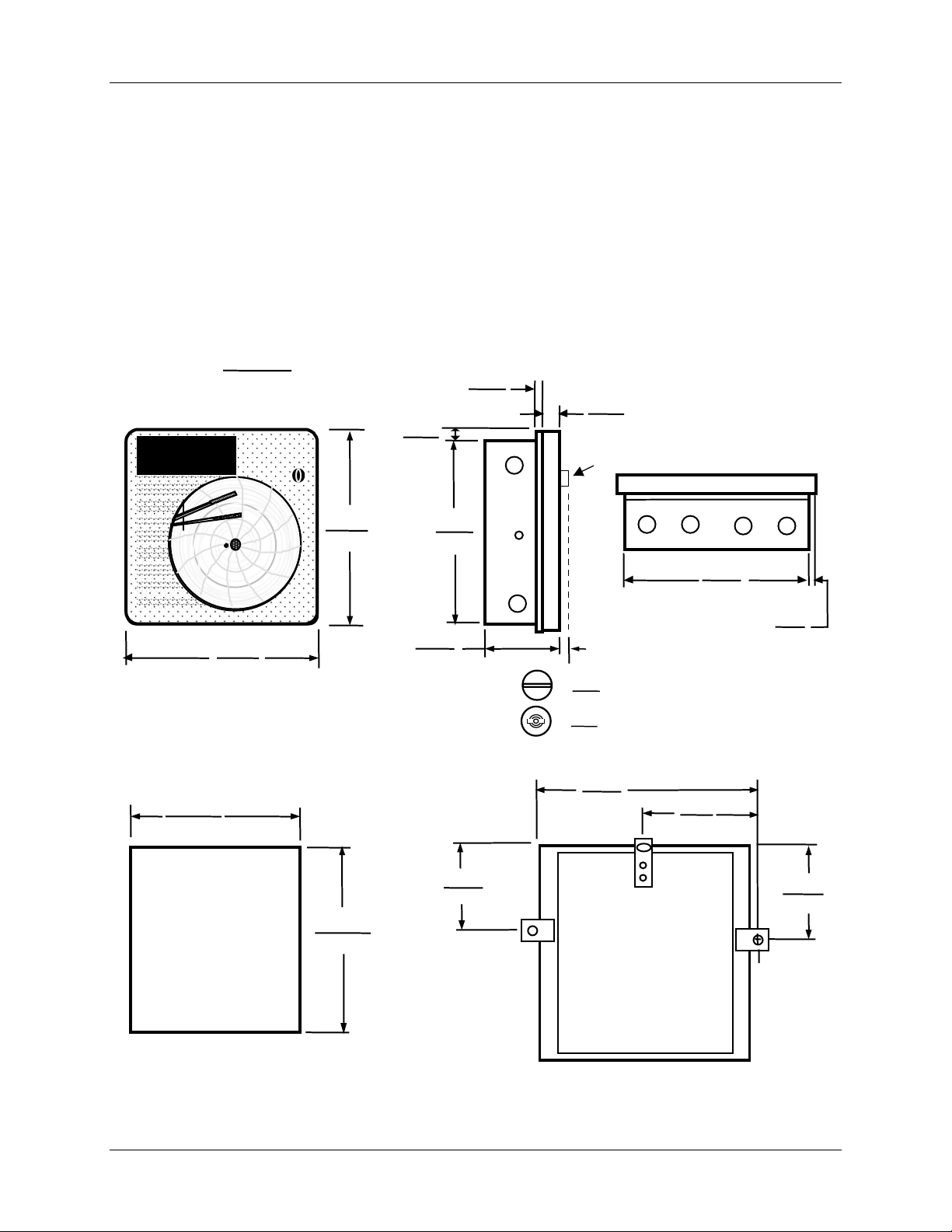
The overall dimensions and panel cutout requirements for mounting the recorder are shown in Figure 2-1.
Installation
Dimensions:
Front View
322.56
12.70
Millimetres
Inches
355.6
14.0
355.6
14.0
Left Side View
Max. panel
thickness
28.6
1.125
23
0.9
320.5
12.6
147.8
5.8
Short wing latch :
Double bit latch
:
14.5
0.57
5
0.19
41.3
1.6
Latch
369.6
14.5
Bottom View
320.5
12.6
17.5
0.6
196.2
7.7
Panel
Cutout
322.56
12.70
163.2
6.4
Surface
Mounting
Rear View
181.3
7.1
24210
Figure 2-1 Overall Dimensions
3/00 DR4300 Circular Chart Recorder Product Manual 15
Page 28
DR4300 Circular Chart Recorder
2.3 Mounting Methods
2.3.1 Introduction
Overview
This section provides instructions for mounting the recorder using one of the following methods:
• Flush in a panel (Subsection 2.3.2)
• Flush in a panel for recorders with NEMA4 or Heavy Duty door (Subsection 2.3.3)
• On a 2-inch pipe (Subsection 2.3.4)
[A pipe mounting kit is available (see Section 9 Parts List).]
• On the surface of a wall or panel (see Subsection 2.3.5).
Choose the method that meets your mounting requirements. Use the associated dimension drawings for
reference.
How to remove knockouts for conduits
Before you mount the recorder, remove the appropriate plugs in the bottom and/or sides of the recorder case
for wire entry via 1/2" (12.7 mm) conduits. Refer to Figure 2-2 for plug locations. To see recommended
use of conduits for various types of wiring, refer to Figure 2-7 and Figure 2-8.
Side View
Bottom View
24211
Figure 2-2 Plug Locations
DR4300 Circular Chart Recorder Product Manual 3/0016
Page 29
2.3.2 Mounting Flush in Panel (New Panel Cutout)
Procedure
Refer to Figure 2-3 and follow the procedure in Table 2-2 to make a new cutout in a panel and mount your
recorder in the cutout.
Table 2-2 Mounting Flush in a New Panel Cutout
Step Action
Installation
1
2
3
4
At the appropriate location, make a square cutout in the panel. Cutout dimensions should be
322.56 mm ± 1.52 mm x 322.56 mm ± 1.52 mm [12.7 in ± 0.060 in x 12.7 in ± 0.060 in]. See
Figure 2-3.
Orient the recorder case properly and slide it into the cutout from the front of the panel.
Support the recorder as shown in Steps 3 and 4.
Refer to Figure 2-3. From the back of the panel, attach a mounting bracket to each side of the
recorder case using a 1/4-20 x 1/2-inch hex screw for each bracket (mounting hardware
supplied with recorder). Leave the screws slightly loose so you can adjust the brackets.
While holding the recorder firmly against the panel, slide each bracket against the back of the
panel and tighten the screws.
Hex screw,
1/4-20 x
1/2 inch and
washer
21406
Figure 2-3 Mounting Flush in a New Panel Cutout (Rear View)
3/00 DR4300 Circular Chart Recorder Product Manual 17
Page 30

DR4300 Circular Chart Recorder
2.3.3 Panel Mounting Recorder with NEMA4 or Heavy Duty door
Refer to Figure 2-4 and follow the procedure in Table 2-3 to panel mount your recorder if it has a NEMA4
or Heavy Duty door.
Table 2-3 Procedure for Mounting Recorder with NEMA4 or Heavy Duty Door
Step Action
Place the panel gasket onto the rear flange of the recorder case.
1
Install four #8-32 screws on each of the three mounting brackets so the ends of the screw
2
threads are flush with the face of the bracket.
NOTE: Screw heads to be flange side of brackets.
Insert the case with gasket into the panel opening.
3
Install one left hand and one right hand bracket with 1/4 x 3/8 long bolts and lockwashers on
4
each side of the case.
NOTE: The notch on each bracket should be facing upward towards the top of the unit.
Do not tighten the hex bolts at this time.
Install the remaining right hand bracket on the top with the 1/4 x 3/4 long bolt and lockwasher.
5
Do not tighten the bolt at this time.
Place a screwdriver blade on the notch of each bracket and firmly tap so that each bracket
6
firmly mates the case with gasket to the panel.
NOTE: Keep brackets parallel to case. Tighten the three 1/4 hex bolts to hold the brackets in
place.
Start to tighten the #8-32 x 1/2 screws on the right side bracket. Alternate screws at opposite
7
ends until all four screws have a minimum of 10 lb-in of torque applied. Do the same to both
the left side and top brackets.
When completed all twelve screws should have a minimum of 10 lb-in of torque applied. This
assures the case and panel gasket are adequately sealed against the panel.
DR4300 Circular Chart Recorder Product Manual 3/0018
Page 31

Installation
Bracket
Hex Head Bolt
1/4-20 x 3/4 inch
Notch
Pan Head Screw
8-32 x 1/2 inch
Hex Head Bolt
1/4-20 x 3/8 inch
NOTE: Mounting brackets and attaching hardware are included in kit 30755065-502;
panel gasket supplied in kit 51197657-501.
Side View
Figure 2-4 Panel Mounting Recorder with NEMA4 or Heavy Duty Door
3/00 DR4300 Circular Chart Recorder Product Manual 19
Page 32

DR4300 Circular Chart Recorder
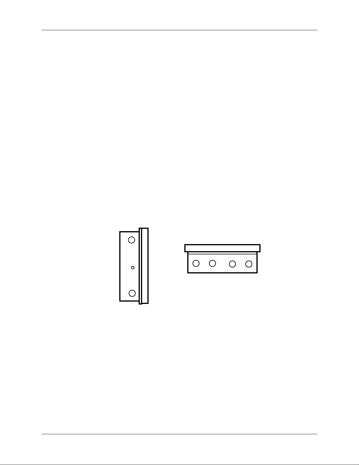
2.3.4 Mounting on a 2-inch pipe
Refer to Figure 2-5 and follow the procedure in Table 2-4 to mount your recorder on a 2-inch pipe.
Table 2-4 Pipe Mounting Procedure
Step Action
Using the eight plastite screws supplied with the pipe mounting bracket kit, attach the two
1
mounting brackets (flat side against the case) to the back of the recorder. Refer to Figure 2-5
for location.
Position the recorder with brackets on the 2-inch pipe.
2
Install the U-bolts around the pipe and through the bracket holes. Secure with lockwashers
3
and hex nuts provided.
Hex Nut
Washer
Rear
of
Case
Figure 2-5 Pipe Mounting Brackets
Pipe Mounting
Bracket
Plastite
Screw
U-bolt
24224
DR4300 Circular Chart Recorder Product Manual 3/0020
Page 33

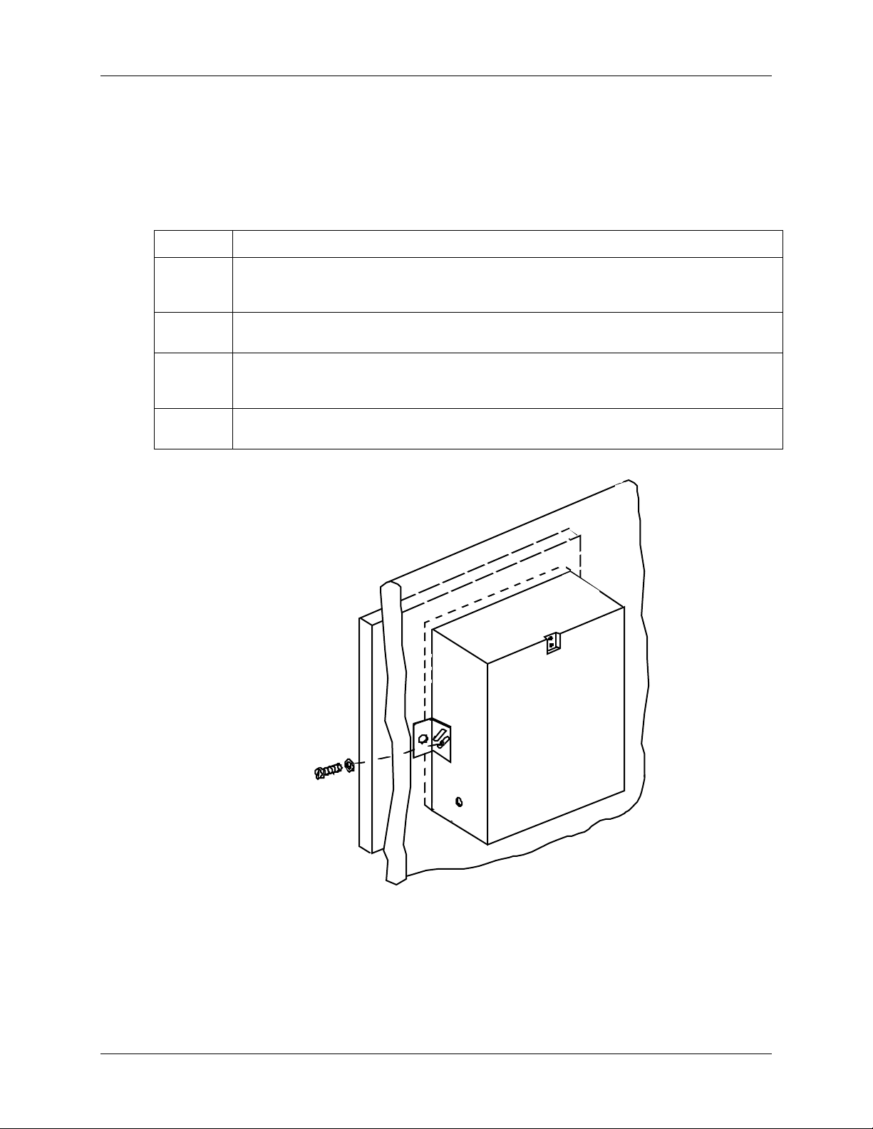
2.3.5 Mounting on Surface (of Panel or Wall)
Procedure
Refer to Figure 2-6 and follow the procedure in Table 2-5 to mount your recorder on a surface (panel or
wall).
ATTENTION
Three (3) screws must be supplied by the user for attaching the mounting hardware (brackets and
support hook) to panel or wall.
Table 2-5 Mounting Flush on a Surface (of Panel or Wall)
Step Action
Installation
1
2
3
4
5
6
7
8
Using two flat-head 10-32 x 1/4-inch screws supplied with the recorder, fasten the support
hook into the recess at the back of the recorder case as shown in Figure 2-6.
Using 1/4-20 x 1/2-inch hex screws and lockwashers, attach a mounting bracket to each side
of the case. Leave the screws slightly loose so as to permit some adjustments of the
brackets.
On the panel, mark the locations for the three holes, as shown by the hole pattern in Figure
2-6.
Using a drill of appropriate size for user-supplied screws, drill a hole in the front of the panel
for the eye of the support hook.
Insert the screws for the support hook into the panel, allowing the screw head to protrude
approximately 5/16-inch.
Hang the recorder support hook on the screw. Make sure that the locations for the other two
holes (marked in Step 3) are correct. If not, make sure that the recorder is aligned vertically,
and use the brackets as templates to mark the proper locations.
Remove the recorder from the panel and drill the other two holes.
Hang the recorder on the screw by the support hook and insert the other two user-supplied
screws through the brackets into the panel. Tighten the two hex screws that attach the
brackets to the case.
3/00 DR4300 Circular Chart Recorder Product Manual 21
Page 34

DR4300 Circular Chart Recorder
Hole Pattern
Reference:
181.36
7.14
196.22
7.725
millimeters
inches
369.6
14.550
18.03
0.710
163.32
6.430
NOTE:
These screws must be supplied by
user; all other mounting hardware
is supplied with recorder.
Support
hook
21409
Figure 2-6 Mounting Flush on a Surface of Panel or Wall (Rear View)
2.4 Wiring Prerequisites
ATTENTION
Wiring should be performed by qualified personnel.
Electrical considerations
The recorder is considered “rack and panel mounted equipment” per EN 61010-1, Safety Requirements for
Electrical Equipment for Measurement, Control, and Laboratory Use, Part 1: General Requirements.
!
Recorder grounding
PROTECTIVE EARTH (GROUND)
Grounding of this recorder shall be in accordance with national and local electrical codes.
NOISELESS (CLEAN) EARTH (GROUND)
To minimize electrical noise and transients that may adversely affect the recorder, connection of the
recorder terminal (located in the rear of the case) to a local earth (ground) using a No. 11 (4 mm
copper conductor is recommended.
2
) braided
DR4300 Circular Chart Recorder Product Manual 3/0022
Page 35

Taking electrical noise precautions
Electrical noise is composed of unabated electrical signals which produce undesirable effects in
measurement and control circuits.
Digital equipment is especially sensitive to the effects of electrical noise. Your recorder has built-in circuits
to reduce the effect of electrical noise from various sources. If there is a need to further reduce these effects:
• Separate External Wiring—Separate connecting wires into bundles (see Table 2-6) and route the
individual bund l es through separate conduits or meta l trays.
• Use Suppression Devices—For additional noise protection, you may want to add suppression devices
at the external source. Appropriate suppression devices are commercially available.
For additional noise information, refer to document 51-52-05-01, How to Apply Digital Instrumentation in
Severe Electrical Noise Environments.
CE conformity special conditions (Europe)
Shielded cables with a drain wire are required for all input and output cables. All instrument shielded cable
drain wires must be connected to a low impedance earth ground at the entry fitting. Cable/conduit entry
fittings shall effectively terminate the cable shield connecting the shield to the enclosure conductive coating.
The shielded cable shield shall not extend into the instrument closure.
Installation
3/00 DR4300 Circular Chart Recorder Product Manual 23
Page 36

DR4300 Circular Chart Recorder
Recommended wiring routing
The case is equipped with numerous knock-outs (plugs) for wiring conduits (see Figure 2-2). To see
recommended use of these points of entry for various types of wiring, refer to Figure 2-7 and Figure 2-8.
RS485/422
Communications
Recommended Wiring Locations for Models without CE Mark
J3
Communications
Printed Circuit Boar d
Pen 2 Main
Printed Circuit Board
P3D
TB4
to TB1)
TB2
TB3
TB1
Digital Input Board Digital Input Board
TB5
L
N
Relay/Alarm
Outputs
A.C. Mains
(Integral wiring
24 V Power Supply
Printed Circuit Board
TB1
Current Outputs 1 and 2
and 24 V Power Supply
Pen 1 Main
TB5
TB4
TB2
P3D
TB3
Digital Inputs 1 and 2
Inputs 1 and 2
24818
Figure 2-7 Recommended Wiring Routing - Models Without CE Mark
DR4300 Circular Chart Recorder Product Manual 3/0024
Page 37

Recommended Wiring Locations for CE Mark Models
Installation
RS485/422
Communications
Relay/Alarm
Outputs
J3
Communications
24 V Power Supply
Printed Circuit Board
Pen 2 Main
Printed C i rcuit Board
P3D
TB4
Filter
Assembly
TB2
TB3
Current Outputs 1 and 2
and 24 V Power Supply
TB1
Digital Input Board Digital Input Board
TB5
A C
A.C. Mains and
Ground Wire
1
Printed Circuit Board
TB1
Pen 1 Main
TB5
TB4
TB2
P3D
TB3
Inputs 1 and 2
24819
Digital Inputs 1 and 2
1
A braided copper shield shall be connected to ground (green screw on the filter assembly).
A separate braide d copper shield shall be use d t o connect
on rear of case to chas si s ground
Figure 2-8 Recommended Wiring Routing - Models With CE Mark
3/00 DR4300 Circular Chart Recorder Product Manual 25
Page 38

DR4300 Circular Chart Recorder
Wire bundling recommendations
Bundling together the wrong wires can adversely affect the recorder’s performance. Table 2-6 shows which
wire functions may usually be bundl ed together. Do not bundle together wires from different categories.
Category Wire Functions
Table 2-6 Wiring Bundling Categories
Wiring diagrams
To determine the appropriate diagrams for wiring your recorder, refer to the model number interpretation in
Section 1 - Overview. The model number of the recorder can be found on the chart plate.
Using the information contained in the model number, select the appropriate wiring diagrams from the
figures listed in Table 2-7 and wire the recorder accordingly.
1
2 Analog signal wire, such as:
3
• Line power wiring
• Earth ground wiring
• Control relay output wiring
• Line voltage alarm wiring
• Input signal wire (thermocouple, 4 to 20 mA, etc.)
• 4-20 mA output signal wiring
• Digital input wiring
• Communication wiring
• Transmitter power out wiring
• Low voltage alarm relay output wiring
• Low voltage wiring to solid state type control circuits
Table 2-7 Wiring Illustrations
Wiring Requirements See
Power Wiring - Models Without CE Mark Figure 2-9
Power Wiring - Models With CE Mark Figure 2-10
Analog Input Wiring Figure 2-11
Digital Input Wiring Figure 2-12
Communication Wiring Figure 2-13
Relay Output Wiring Figure 2-14
Open Collector Relay Output Wiring Figure 2-15
Current Output Wiring Figure 2-16
Transmitter Power Out Wiring Figure 2-17
DR4300 Circular Chart Recorder Product Manual 3/0026
Page 39

2.5 Input Wiring
Introduction
This section describes procedures for wiring power, analog inputs, optional digital inputs, and the optional
communication link.
2.5.1 Power Wiring
Introduction
Recorder models are available for use with 100 to 240 Vac or 20 Vdc to 27 Vdc power. (See Model
Number in Section 1 Overview.)
Procedure
The procedure to connect power wiring is in Table 2-8.
• See
• Figure 2-9 for models without CE Mark.
Installation
• See
• Figure 2-10 for models with CE Mark.
WARNING
SHOCK HAZARD
Be sure that the line voltage is OFF before connecting the power wires to the recorder.
Failure to observe this precaution can result in serious personal injury or death.
CAUTION
This equipment is suitable for connection to 100 to 240 Vac (49 to 61 Hz) or 20 to 27 Vac/Vdc power
supply mains. It is the user’s responsibility to provide a switch and non-time delay (North
!
America), quick-acting, high breaking capacity, Type F, (Europe) 1/2 A, 250 V fuse(s) or circuitbreaker as part of the installation. The switch or circuit-breaker shall be located in close proximity
to the recorder, within easy reach of the operator. The switch or circuit-breaker shall be marked as
the disconnecting device for the recorder.
3/00 DR4300 Circular Chart Recorder Product Manual 27
Page 40

DR4300 Circular Chart Recorder
Step Action
Table 2-8 Procedure for Power Wiring Models
1
2
3
4
ATTENTION: To avoid damaging the recorder, be sure that you install the power wires into the
correct screw terminals as shown Figure 2-9 and Figure 2-10.
5
6
Open the recorder door. Loosen the captive screw in the chart plate and swing the plate out.
Locate the power terminal block for your recorder model.
• See Figure 2-9 for models without CE Mark.
• See Figure 2-10 for models with CE Mark.
Note that the power connection between the boards on two-pen models is made at the
factory. On CE Mark and UL models the connection between the terminal block at the
bottom of the case and the PCA is also made at the factory. In all models, you only have
to connect power to a single terminal block.
Run the power wires separately through the conduit hole indicated in Figure 2-7 or Figure
2-8.
Strip 1/4-inch maximum of insulation from the end of each wire and form end to fit under a
screw connection.
Tighten the screws to secure the wires.
Dress the wires with as much slack as possible. Do not bundle any low level signal wires with
the power wires. Refer to Table 2-6 for permissible wire bundling.
Refer to Appendix A for additional information concerning noise interference prevention.
WARNING
Input line voltage may be present on the instrument ground plane if earth ground is not
attached.
Failure to observe this precaution can result in serious personal injury.
SHOCK HAZARD
DR4300 Circular Chart Recorder Product Manual 3/0028
Page 41

Installation
Main PCA
Pen 2
7
TB2
TB1
4
5
L
N
7
TB1
Main PCA
Pen 1
TB2
TB6
2
1
L2/N L1/H
100 Vac to 240 Vac
24821
3
It is the user’s responsibility to provide a switch and
1
non-time delay (North America), quick-acting, high
breaking capacity, Type F, (Europe) 1/2 A, 250 V
fuse(s) or circuit-breaker as part of the installation.
2
PROTECTIVE EARTH (Ground): Grounding of
this recorder shall be in accordance with National
and Local electrical codes.
3
NOISELESS (Clean) EARTH (Ground): To minimize
electrical noise and transients that may adversely
affect the recorder, connection of the recorder terminal
(located in the rear of the case) to a local earth
(ground), using a No. 11 (4 mm
2
) braided copper
conductor, is required.
4
For 2 Pen Recorder/Controller, connect ac power
to TB1 of Pen 2 PCA. Supply connections must be
made at TB6, if installed.
5
Wire ac power to this connector if installed.
Figure 2-9 Power Wiring – Models Without CE Mark
3/00 DR4300 Circular Chart Recorder Product Manual 29
Page 42

DR4300 Circular Chart Recorder
TB1
Main PCA
Pen 2
7
TB2
7
TB1
Main PCA
Pen 1
TB2
LN
It is the user’s responsibility to provide a switch and
1
non-time delay (North America), quick-acting, high
breaking capacity, Type F, (Europe) 1/2 A, 250 V
fuse(s) or circuit-breaker as part of the installation.
2
PROTECTIVE EARTH (Ground): Grounding of
this recorder shall be in accordance with Natio nal
and Local electrical codes.
3
NOISELESS (Clean) EARTH (Ground): To minimize
electrical noise and transients that may adversely
affect the recorder, connection of the recorder terminal
(located in the rear of the case) to a local earth
(ground), using a No. 11 (4 mm
2
) braided copper
conductor, is required.
Figure 2-10 Power Wiring – Models With CE Mark
Ground
Screw
L
N
2
1
L2/NL1/H
100 Vac to 240 Vac
24820
3
2
DR4300 Circular Chart Recorder Product Manual 3/0030
Page 43

2.5.2 Analog Input Wiring
Introduction
The input for pen channel 1 is wired to TB2 on the printed circuit assembly (PCA) on the right (when facing
recorder). The input for pen channel 2 is wired to TB2 on the PCA on the left.
Each input can be wired for thermocouple, RTD, mA, mV, or Volt actuations.
ATTENTION
Make sure you have configured the recorder to accept the desired input type. See Section 3 –
Configuration, Startup, and Operation of Recorder Without Display or Section 4 – Configuration,
Startup, and Operation of Recorder With Display.
Procedure
Refer to Figure 2-11 while following the procedure in Table 2-9 to install analog input wiring.
Installation
Table 2-9 Analog Input Wiring
Step Action
ATTENTION To avoid damaging the recorder, be sure that you install the power wires into the
correct screw terminals as shown in Figure 2-9 and Figure 2-10.
1
2
3
4
5
6
7
Turn off the power to the recorder.
Open the recorder door. Loosen the captive screw in the chart plate and swing the plate out.
Locate terminal block TB2 on the right edge of the printed circuit assembly for pen 1 (refer to
Figure 2-11).
Run the input wires through the appropriate conduit hole (see Figure 2-7 and Figure 2-8). DO
NOT bundle them with the power wires.
Strip 1/4-inch maximum of insulation from the end of each wire and form end to fit under the
screw terminal on the removable connection block.
Insert the wires under the appropriate screws for the applicable input type. See Figure 2-11 for
specific input actuation wiring.
Tighten the screws to secure the wires.
If the recorder has two pens, repeat Steps 3 through 6 to wire the input for the second pen
channel to TB2 on the PCA on the left inside of the recorder.
3/00 DR4300 Circular Chart Recorder Product Manual 31
Page 44

DR4300 Circular Chart Recorder
+ White
J
•
- Red
+ Yellow
K
- Red
+ Blue
T
- Red
+ Black
R
- Red
+ Black
S
- Red
+ Purple
E
-
Red
+ Gray
B
- Red
+ Orange
N
- Red
Standard used as color
reference ANSI MC96.1
7
TB1
RTD
mA, mV or
Volt source
Main PCA
Pen 2
Thermocouple
T/C
mA, mV or Volt
+
RTD
Main PCA
Pen 1
7
TB2
TB1
TB2
–
R
TB2
+
–
R
TB2
+
Be sure that thermocouple
extension wire matches
thermocouple type
•
100 ohm maximum lead resistance
•
Keep resistance of all wires equal
•
Use 18 gauge copper wire for lengths up
to 150 feet.
For two wire RTD jumper terminal
•
negative (-) to R.
• Many 3-wire RTDs use color coded
wires. One wire is a different color than
the other two. The single wire is usually
the positive connection
TB2
24086
–
R
Figure 2-11 Analog Input Wiring
DR4300 Circular Chart Recorder Product Manual 3/0032
Page 45

2.5.3 Digital Inputs (Optional)
Introduction
If the recorder hardware supports optional digital inputs, the inputs are wired to the terminal block on the
digital input board mounted on stand-offs on the printed circuit assembly for the pen channel.
Procedure
Refer to Figure 2-12 while following the procedure in Table 2-10 to install digital input wiring.
Step Action
ATTENTION To avoid damaging the recorder, be sure that you install the power wires into the
correct screw terminals as shown in Figure 2-9 and Figure 2-10.
Installation
Table 2-10 Digital Input Wiring
1
2
3
4
5
6
Open the recorder door. Loosen the captive screw in the chart plate and swing the plate out.
Locate the terminal block, P3D, on the optional digital input printed circuit assembly mounted
on stand-offs above the printed circuit assembly (PCA) for the pen channel. The PCA on the
right inside the recorder is for pen 1; if there is a second pen, its PCA is on the left. (See
Figure 2-12.)
Run the input wires through the appropriate conduit hole (see Figure 2-7 and Figure 2-8). DO
NOT bundle them with the power wires.
Strip 1/4-inch maximum of insulation from the end of each wire and form end to fit under a
screw connection.
Insert the wires under the appropriate screws for the input number (labeled on assembly).
Tighten the screws to secure the wires.
If the recorder has two pens, repeat Steps 2 through 5 to wire the input for the second pen
channel.
3/00 DR4300 Circular Chart Recorder Product Manual 33
Page 46

DR4300 Circular Chart Recorder
TB1
Main PCA
Pen 2
7
TB2
7
TB1
Main PCA
Pen 1
TB2
Digital
Input PCA
J9
P3D
Figure 2-12 Digital Input Wiring
24142
Digital
Input
Switch #1
Digital
Input
Switch #2
Connect shield
to ground at
one end only
Switch
Common
DR4300 Circular Chart Recorder Product Manual 3/0034
Page 47

2.5.4 Communication (Optional)
Introduction
If the recorder hardware supports optional Modbus RTU communication, the communication link is wired
to the terminal block on the communication board in the upper left corner of the case.
ATTENTION
Network address, baud rate, and transmitter delay are configurable for models with a display (see
Section 4).
For models without a display the address of pen 1 is fixed at 127, baud rate is fixed at 9600, and
there is no transmitter delay. Only one pen channel with the fixed address of 127 can be on the
network. Pen channel 2, if present in the recorder, cannot communicate. (Display is required to
configure a unique address for the second pen to communicate.)
Procedure
Refer to Figure 2-13 while following the procedure in Table 2-11 to install communication wiring.
Installation
Table 2-11 Communication Wiring
Step Action
ATTENTION To avoid damaging the recorder, be sure that you install the power wires into the
correct screw terminals as shown Figure 2-9 and Figure 2-10.
1
2
3
4
5
Open the recorder door. Loosen the captive screw in the chart plate and swing the plate out.
Locate the terminal block on the optional communication printed circuit assembly in the upper
left corner of the case. (See Figure 2-13.)
Run the communication wires through the appropriate conduit hole (see Figure 2-7 and Figure
2-8). DO NOT bundle them with the power wires.
Strip 1/4-inch maximum of insulation from the end of each wire and form end to fit under a
screw connection.
Insert the wires under the appropriate screws (labeled on assembly). Tighten the screws to
secure the wires.
3/00 DR4300 Circular Chart Recorder Product Manual 35
Page 48

DR4300 Circular Chart Recorder
Communication PCA
J3
7
7
Main PCA
Pen 1
TB1
TB2
TB2
TB1
Main PCA
Pen 2
24822
Communications ma ster
_
+
See
Note
Tx+/
Rx+
SHLD
120 Ohm
Resistor
Tx–/
Rx–
NOTE: The shield of the
communication cable is connected
to ground at the recorder end, and
should not extend into the recorder
enclosure.
Figure 2-13 Communication Wiring
DR4300 Circular Chart Recorder Product Manual 3/0036
Place 120 Ohm Resistor on
last device, between Tx+/Rx+
and Tx–/Rx–.
To other
communications
instruments
(Max imum 15 )
Optional communication
Page 49

2.6 Output Wiring
ATTENTION
The recorder is available with several options and multiple output algorithms. Output terminal use
depends on which output algorithm and options are used. The wiring diagrams in this section
show how to wire the terminals. To see which terminals are used for what output function, refer to
Table 2-12. This table applies to all control types. Each pen channel is configured separately, and
each can use a different output algorithm. (The output algorithm is set with the control set up
group “OUTALG” parameter.)
Table 2-12 Output Terminal Use for Output Algorithm and Option Combinations
Installation
Terminal Function
OUTALG value Current Out
NONE auxilary output* alarm 1 alarm 2 or timer*
RLY auxilary output* control alarm 2 or timer*
RLYD auxilary output* control 1 (heat) control 2 (cool)
CUR control alarm 1 alarm 2 or timer*
CurT control (cool) control (heat) alarm 2 or timer*
Tcur control (heat) control (cool) alarm 2 or timer*
*Option
2.6.1 Discrete Outputs
Introduction
Each pen channel in the recorder models having display and keypad can be equipped with two optional
discrete out puts. These o ut puts can be used for control or alarming, dep ending on the configuration as
described in Section 4 – Configuration, Startup, and Operation of Recorder with Display.
Three types of discrete outputs are available:
• electromechanical relay
(TB5)
Relay 1
(TB4)
Relay 2
(TB3)
• solid state relay
• open collector output
ATTENTION
The electromechanical relays on the printed circuit assembly (PCA) for each pen channel can be wired for
Normally Open (NO) and Normally Closed (NC) operation.
ATTENTION
The DR4300 is available as a limit controller. In a limit controller each pen channel’s printed circuit
assembly Relay 1 (TB4 terminals 3 and 2 for NO contacts, and 2 and 1 for NC contacts) is used for
limit control. When the recorder detects that the input has exceeded the limit (or fallen below the
limit, depending on configuration), the controller goes to the limit state: Relay 1 is de-energized.
3/00 DR4300 Circular Chart Recorder Product Manual 37
Page 50

DR4300 Circular Chart Recorder
Insulation of output wires
The insulation of wires connected to the relay output terminals shall be rated for the highest voltage
involved. Ext ra Low Voltage (ELV) wiring (input, current outp ut, and low voltage control/alarm circuits)
shall be separated from HAZARDOUS LIVE (>30 Vac, 42.4 Vpeak or 60 Vdc) wiring per Table 2-6.
Procedure
Follow the procedure in Table 2-13 to wire the discrete outputs.
Refer to Figure 2-14 for wiring electromechanical and solid state relays.
Refer to Figure 2-15 for wiring open collector outputs.
Refer to Table 2-12 to see the output function of each terminal with the available output algorithms and
options.
Table 2-13 Relay Output Wiring - 1 or 2 Pen Models
Step Action
ATTENTION To avoid damaging the recorder, be sure that you install the power wires into the
correct screw terminals as shown in Figure 2-9 and Figure 2-10.
1
2
3
4
5
6
Turn off the power to the recorder.
Open the recorder door. Loosen the captive screw in the chart plate and swing the plate out.
Locate terminal blocks TB3* and TB4* on the bottom right edge of the printed circuit assembly
(PCA) for pen 1 or pen 2.
Run the output wires through the appropriate conduit hole (see Figure 2-7 and Figure 2-8).
DO NOT bundle them with input wires.
Strip 1/4-inch maximum of insulation from the end of each wire and form end to fit under a
screw connection.
Insert the wires under the appropriate screws for the applicable relay output as shown in the
figures. Tighten the screws to secure the wires.
*TB3 is output 2.
TB4 is output 1.
DR4300 Circular Chart Recorder Product Manual 3/0038
Page 51

Installation
TB4
To terminal
1 or 3
7
TB1
321
Relay #1
Load
Main PCA
Pen 2
TB3
321
Relay #2
Load
To terminal
1 or 3
TB2
TB1
7
OR
Main PCA
Pen 1
TB4
321
Relay #1
TB2
Load
24823
321
Relay #2
1
Load
TB3
1
2
Load
Supply
Power
Electromechanical
Relay Output Wiring
1
If the load current is less tha n the minimum rated value of 20 mA, there may be a residual voltag e
across both ends of the load ev en if the relay is turned off. Use a dummy resistor as shown to
counteract this. The total current through the resistor and the load current must exceed 20 mA.
2
Solid State relays are ra ted at 0.5 Amps. Size fuses acc ordingly.
Load
Supply
Power
Load Supply
Power
Solid State Relay
Output Wiring
Load Supply
Power
Figure 2-14 Relay Output Wiring
3/00 DR4300 Circular Chart Recorder Product Manual 39
Page 52

DR4300 Circular Chart Recorder
TB1
Main PCA
Pen 2
7
7
TB2
TB1
Main PCA
Pen 1
TB2
24145A
0 to 30 Vac
––+
TB4
321
_
+
Customer Supplied
Electromechanical Relay
Figure 2-15 Open Collector Output Wiring
321
_
0 to 30 Vac
+
TB3
+
OR
–
321
Customer Supplied
Solid State Relay
–++
TB3TB4
321
DR4300 Circular Chart Recorder Product Manual 3/0040
Page 53

2.6.2 Current Output
Introduction
4 to 20 mA current outputs are optionally available for each pen channel in the recorder models having
display and keypad.
Insulation of output wires
The insulation of wires connected to the relay output terminals shall be rated for the highest voltage
involved. Ext ra Low Voltage (ELV) wiring (input, current outp ut, and low voltage control/alarm circuits)
shall be separated from HAZARDOUS LIVE (>30 Vac, 42.4 Vpeak or 60 Vdc) wiring per Table 2-6.
Procedure
Refer to Figure 2-16 and follow the procedure in Table 2-14 to wire the current outputs.
Refer to Table 2-12 to see the output function of TB5 with the available output algorithms and options.
Step Action
Installation
Table 2-14 Current Output Wiring
ATTENTION To avoid damaging the recorder, be sure that you install the power wires into the
correct screw terminals as shown in Figure 2-9 and Figure 2-10.
1
2
3
4
5
6
Turn off the power to the recorder.
Open the recorder door. Loosen the captive screw in the chart plate and swing the plate out.
Locate terminal block TB5 on the printed circuit assembly (PCA) for pen 1 or pen 2. (See
Figure 2-16.)
Run the output wires through the appropriate conduit hole (see Figure 2-7 and Figure 2-8).
Refer to Table 2-6 for acceptable wire bundling.
Strip 1/4-inch maximum of insulation from the end of each wire and form end to fit under a
screw connection.
Insert the wires under the appropriate screws for the applicable relay output as shown in the
figure. Tighten the screws to secure the wires.
3/00 DR4300 Circular Chart Recorder Product Manual 41
Page 54

DR4300 Circular Chart Recorder
7
TB1
Current
Output
or
Auxiliary
Output
Main PCA
Pen 2
TB2
_
Main PCA
Pen 1
7
TB2
TB1
24824
TB5
+
Load
0-600 Ohms
Figure 2-16 Current Output Wiring
DR4300 Circular Chart Recorder Product Manual 3/0042
Page 55

2.6.3 Transmitter Power Out
Introduction
A recorder model is available that provides +24 Vdc power out to a transmitter.
Procedure
Refer to Figure 2-17 and follow the procedure in Table 2-15 to wire the transmitter power out.
Table 2-15 Transmitter Power Out Wiring
Step Action
ATTENTION To avoid damaging the recorder, be sure that you install the power wires into the
correct screw terminals as shown in Figure 2-9 and Figure 2-10.
Installation
1
2
3
4
5
6
Turn off the power to the recorder.
Open the recorder door. Loosen the captive screw in the chart plate and swing the plate out.
Locate the DC OUT terminal block on the Transmitter Power Module, located above the
printed circuit assembly (PCA) for pen 1. (See Figure 2-17.)
Run the output wires through the appropriate conduit hole (see Figure 2-7 and Figure 2-8).
Refer to Table 2-6 for acceptable wire bundling.
Strip 1/4-inch maximum of insulation from the end of each wire and form end to fit under a
screw connection.
Insert the wires under the appropriate screws for the transmitter power out as shown in the
figure. Tighten the screws to secure the wires.
3/00 DR4300 Circular Chart Recorder Product Manual 43
Page 56

DR4300 Circular Chart Recorder
Main PCA
Pen 2
7
TB2
TB1
* See transmitter’s instruction manual for
power supply/receiver wiring details.
Main PCA
Pen 1
7
TB2
TB1
Transmitter Power Module
-V
+V
Pen #1
TB2
+
–
–
R
Pen #2
TB2
–
+
XMTR
–
R
24 V Output
50 mA maximum
24 Vdc*
XMTR
+
24 Vdc*
+
Figure 2-17 Transmitter Power Out Wiring
NOTE: Ensure switches on SW6 are set to their correct positions prior to applying power
to transmitter supply.
For switch settings see Table 3-2 (recorders without display) or Table 4-3 (recorders with display).
DR4300 Circular Chart Recorder Product Manual 3/0044
Page 57

3. Configuration, Startup, and Operation of
3.1 Overview
Introduction
Set up the functionality of the models that do not have a display and keypad using configuration and input
switches. Each pen channel in the recorder has an associated printed circuit assembly (PCA) shown in
Figure 3-1. The configuration switches are the SW1 switchbank. The input switches are the SW6
switchbank. If your recorder is equipped with two pens, the printed circuit assemblies for the two pens can
be set up differently. The PCA for pen 1 (purple) is on the right (when facing the recorder); the PCA for pen
2 (red) is on the left (if present).
Set up is fast and easy. This section includes a table that shows the various available combinations of
recording selections (such as chart range, length of time for single rotation of chart, whether the input is
linear or non-linear), input actuation types, and whether jumper R56 should be in or out. Find your desired
configuration for the pen 1 channel on the table, then set the SW1 and SW6 switches as indicated. Repeat
the process for the pen 2 channel, if available on your recorder, and set up is complete.
Configuration, Startup, and Operation
of Recorder without Display
Basic Recorder without Display
What’s in this section?
The following is a list of topics covered in this section.
3.1 Overview 45
3.2 Configuration (Recording Set Up) 46
3.3 Startup and Operation 65
SET THE SWITCHES DESCRIBED IN THIS SECTION WITH THE UNIT
POWER DISCONNECTED. DO NOT TOUCH POWER CONNECTIONS
AT TB1. FAILURE TO OBSERVE THIS PRECAUTION CAN RESULT IN
EXPOSURE TO A POTENTIALLY LETHAL SHOCK HAZARD. MORE THAN
ONE SWITCH MAY BE REQUIRED TO DE-ENERGIZE UNIT.
Topic See Page
!
WARNING—SHOCK HAZARD
4/00 DR4300 Circular Chart Recorder Product Manual 45
Page 58

DR4300 Circular Chart Recorder
3.2 Configuration (Recording Set Up)
3.2.1 Setting Configuration and Input Switches
Introduction
Configuration switches SW1 (see Figure 3-1) and input switches SW6 are provided on each printed circuit
assembly associated with a pen channel. If your recorder is equipped with two pens, the printed circuit
assemblies for the two pens can be set up differently.
Table 3-2 shows the various available combinations of recording selections (such as chart range, length of
time for single rotation of chart, whether input is linear or non-linear), input actuation types, and whether
jumper R56 should be in or out.
Figure 3-2 shows a sample chart for a 1-pen recorder.
Procedure
Follow the procedure in Table 3-1 to set up your recorder model without display. (To set up a model with a
display see Section 4 – Configuration, Startup, and Operation of Recorder with Display.)
The procedure described here assumes that the chart door is opened, the chart plate is swung out, and the
power is removed.
WARNING
SHOCK HAZARD
When the unit is powered a potentially lethal shock hazard exists at the AC line connections at TB1 on
each printed circuit assembly. Make sure the unit power is disconnected before starting the procedure.
More than one switch may be required to de-energize the recorder.
Failure to observe this precaution can result in exposure to a potentially lethal shock hazard.
Table 3-1 Procedure for Configuring Model without Display
Step Action
1
2
3
4
5
ATTENTION
Turn off the power to the recorder.
Go to Table 3-2 and find the desired combination of recording selections and input type for the
pen 1 channel.
Set the switches in SW1 and SW6 on the pen 1 printed circuit assembly (the PCA on the right
when facing recorder) as indicated in Table 3-2. (Pen 1 is purple.)
Repeat for pen 2 channel (if available).
For each PCA, make a note of the number assigned to the configuration (from first column of
Table 3-2). If you have to call Honeywell Technical Assistance for help, tell the support staff
the configuration number(s) of the pen channel(s) in your recorder to speed up the
troubleshooting process.
If you set the switches in an ON/OFF combination that does not match any of the configurations in
Table 3-2, the recorder will use configuration #1.
46 DR4300 Circular Chart Recorder Product Manual 4/00
Page 59

Configuration, Startup, and Operation
of Recorder without Display
Jumper
Configuration
Switches
S2 = Reset
S3 = Lower
S4 = Raise
AC Power
Run/Setup
Switch
Pen #2 Connector
P1 P2 P3
SW1
8
7
6
5
4
3
2
ON
1
SW2
LN
SETUP
SW5
TB1
RUN
Pen #1 Connector
Chart Motor
R56
SW3
LOWER RAISE
SW4
Battery
Connector
J1
Communications
Board Connector
J3
123456
ON
SW6
J4
Keyboard/Display
Connector
Input Switches
TB2
Input Connector
24194
Figure 3-1 Location of Configuration and Input Switches
4/00 DR4300 Circular Chart Recorder Product Manual 47
Page 60

DR4300 Circular Chart Recorder
Configuration and Input switch settings for sample chart
Configuration Switch S1
12345678
M
P
6
M
P
7
on on onoff
M
P
8
P
4
C
/
T
/
J
C
M
P
0
5
5
4
1
1
O
T
0
0
4
1
M
P
9
off off
M
P
3
M
0
0
2
0
1
0
1
0
8
0
0
1
0
2
1
M
P
0
1
M
off off
M
P
2
0
8
0
6
0
4
0
6
P
1
1
T
0
4
0
2
0
2
C
/
T
/
H
G
I
N
D
I
0 TO 150 C J /T/C
1
4
0
1
2
0
1
0
0
8
0
6
0
4
0
2
0
E
Y
W
N
E
O
L
H
L
0
2
0
4
0
6
0
8
0
0
1
0
2
1
0
4
1
J
C
0
5
1
O
T
0
M
1
A
M
Input Switch S6
123456
off off off
N
O
O
N
2
0
2
0
4
0
0
2
A
M
off
X off
4
0
on
1
1
A
M
8
0
6
0
6
8
0
1
0
0
0
3
A
M
X = Don’t care
1
0
A
M
9
A
M
0
T
O
1
1
5
0
4
0
1
1
0
0
1
2
1
4
0
J
/
T
/
C
M
24082
C
2
J
0
C
A
/
T
/
C
5
0
A
T
M
O
1
5
0
4
8
A
M
7
A
M
6
A
M
Summary of Input Set Up Switch S6 Functions
123456
200 mV Burnout RTD Volts mV mA
Figure 3-2 Sample Chart for Single Pen Recorder
48 DR4300 Circular Chart Recorder Product Manual 4/00
Page 61

8
7
ON
6
5
4
3
2
CONFIG SWITCHES
Input
Type
1
Stored
Configuration
Stored
Configuration
Configuration, Startup, and Operation
of Recorder without Display
Table 3-2 Configuration and Input Switch Settings for Models without Display
o = off n = on
Any RTD marked with an asterisk is IEC Alpha = 0.00391
All other RTDs are IEC Alpha = 0.00385
x in column for SW6 switch 2 = see Subsection 3.2.2
Chart Type Con-
fig #
0
255
256
EU Non-
Lin
CONFIG Switches
(SW1)
12345678 123456
INPUT Switches
(SW6)
oooooooo oooooo
nnnnnnnn oxoono
oooooooo oooooo
ON
INPUT SWITCHES
Chart Part
Number
6
5
4
3
2
1
R56
out
***
in
in
0-1
Volt
0-5
Volt
0-10
Volt
1-5
Volt
2-10
Volt
0-20
mA
4-20
mA
0-10
mV
0-100
mV
0-200
mV
0-1
Volt
Any linear chart
8 Hr
Any linear chart
8 Hr
Any linear chart
8 Hr
Any linear chart
8 Hr
Any linear chart
8 Hr
Any linear chart
8 Hr
Any linear chart
8 Hr
Any linear chart
8 Hr
Any linear chart
8 Hr
Any linear chart
8 Hr
Any linear chart
12 Hr
291
288
292
289
297
296
290
293
294
295
301
nnooonoo oxonoo
ooooo n oo oxo noo
oonoo n oo oxo noo
noooonoo oxonoo
noononoo oxonoo
ooono n oo oxo noo
onooonoo oxonoo
nonoonoo oxonoo
onnoonoo oxonoo
n n n oo n oo nxoooo
nonnonoo oxonoo
out
out
out
out
out
out
out
out
out
out
out
0-5
Volt
0-10
Volt
1-5
Volt
2-10
Volt
0-20
mV
Any linear chart
12 Hr
Any linear chart
12 Hr
Any linear chart
12 Hr
Any linear chart
12 Hr
Any linear chart
12 Hr
298
302
299
307
306
onononoo oxonoo
onnnonoo oxonoo
nnononoo oxonoo
nnoonnoo oxonoo
onoon noo oxonoo
out
out
out
out
out
4/00 DR4300 Circular Chart Recorder Product Manual 49
Page 62

DR4300 Circular Chart Recorder
8
7
ON
6
5
4
3
2
CONFIG SWITCHES
Input
Type
1
Chart Type Con-
Any RTD marked with an asterisk is IEC Alpha = 0.00391
x in column for SW6 switch 2 = see Subsection 3.2.2
fig #
o = off n = on
All other RTDs are IEC Alpha = 0.00385
EU Non-
Lin
CONFIG Switches
(SW1)
12345678 123456
INPUT Switches
(SW6)
ON
INPUT SWITCHES
Chart Part
Number
6
5
4
3
2
1
R56
***
4-20
mA
0-10
mV
0-100
mV
0-200
mV
0-1
Volt
0-5
Volt
0-10
Volt
1-5
Volt
2-10
Volt
0-20
mA
4-20
mA
Any linear chart
12 Hr
Any linear chart
12 Hr
Any linear chart
12 Hr
Any linear chart
12 Hr
Any linear chart
24 Hr
Any linear chart
24 Hr
(default setting)
Any linear chart
24 Hr
Any linear chart
24 Hr
Any linear chart
24 Hr
Any linear chart
24 Hr
Any linear chart
24 Hr
300
303
304
305
4
1**
5
2
200
9
3
oon no n oo oxon oo
nnnnonoo oxoono
oooon n oo oxoon o
nooo n n oo nxoooo
oonooooo oxo noo
nooooooo oxonoo
nonooooo oxonoo
onoooooo oxonoo
ooonoo n n oxo noo
noonoooo oxonon
nnoooooo oxonon
out
out
out
out
24001660-tab in
24001660-tab in
24001660-tab in
24001660-tab in
24001660-tab in
24001660-tab in
24001660-tab in
0-10
mV
0-100
mV
0-200
mV
0-1
Volt
0-5
Volt
0-10
Volt
1-5
Volt
Any linear chart
24 Hr
Any linear chart
24 Hr
Any linear chart
24 Hr
Any linear chart
7 Day
Any linear chart
7 Day
Any linear chart
7 Day
Any linear chart
7 Day
13
10
14
11
6
7
8
onnooooo oxoono
nnnooooo oxoono
ooonoooo nxoooo
nonnoooo oxonoo
ononoooo oxonoo
onnnoooo oxonoo
nnonoooo oxonoo
24001660-tab in
24001660-tab in
24001660-tab in
24001661-tab in
24001661-tab in
24001661-tab in
24001661-tab in
50 DR4300 Circular Chart Recorder Product Manual 4/00
Page 63

8
7
ON
6
5
4
3
2
CONFIG SWITCHES
Input
Type
1
Chart Type Con-
fig #
Configuration, Startup, and Operation
o = off n = on
Any RTD marked with an asterisk is IEC Alpha = 0.00391
All other RTDs are IEC Alpha = 0.00385
x in column for SW6 switch 2 = see Subsection 3.2.2
EU Non-
Lin
CONFIG Switches
(SW1)
12345678 123456
INPUT Switches
(SW6)
of Recorder without Display
6
ON
5
4
3
2
INPUT SWITCHES
Chart Part
Number
1
R56
***
2-10
Volt
0-20
mA
4-20
mA
0-10
mV
0-100
mV
0-200
mV
B t/c
E t/c
J t/c
J t/c
J t/c
J t/c
J t/c
J t/c
J t/c
J t/c
J t/c
J t/c
J t/c
J t/c
J t/c
J t/c
Any linear chart
7 Day
Any linear chart
7 Day
Any linear chart
7 Day
Any linear chart
7 Day
Any linear chart
7 Day
Any linear chart
7 Day
0 to 1800 °C
24 Hr
0 to 250 °C
24 Hr
0 to 100 Even
24 hr
0 to 100 Even
7 Day
0 to 100 Even
24 hr
0 to 100 Even
7 Day
–45 to 150 °C
24 Hr
–45 to 150 °C
7 Day
0 to 150 °C
24 Hr
0 to 150 °C
7 Day
0 to 150 Even
24 Hr
0 to 150 Even
7 Day
0 to 200 °F
24 Hr
0 to 200 Even
24 Hr
0 to 200 Even
24 Hr
0 to 200 Even
7 Day
201
18
12
15
16
17
78 x
41 x
197 °F
198 °F
230 °C
231 °C
108 x
109 x
25 x
26 x
232 °F
233 °F
35 x
129 °F
132 °C
135 °F
noonoonn oxonoo
onoonooo oxonon
oon noooo oxon o n
nnnnoooo oxoono
oooon ooo oxoono
nooo n ooo nxoooo
on n n oo n o oxoon o
noononoo oxoono
nonooo n n oxoon o
on nooo n n oxoon o
onnoonn n oxoono
nnnoonn n oxoono
oonnon no oxoono
oonnon no oxoono
noonnooo oxoono
onon nooo oxoono
ooononnn oxoono
noononn n oxoono
n nooo n oo oxoon o
noooooo n oxoon o
oonoooon oxoono
nnnoooon oxoono
24001661-tab in
24001661-tab in
24001661-tab in
24001661-tab in
24001661-tab in
24001661-tab in
1660-135 in
in
1660-001 in
1661-001 in
1660-001 in
1661-001 in
1660-027 in
1661-027 in
1660-070 in
1661-070 in
1660-180 in
in
1660-114 in
1660-010 in
1660-010 in
1661-004 in
4/00 DR4300 Circular Chart Recorder Product Manual 51
Page 64

DR4300 Circular Chart Recorder
8
7
ON
6
5
4
3
2
CONFIG SWITCHES
Input
Type
J t/c
J t/c
J t/c
J t/c
J t/c
J t/c
J t/c
J t/c
J t/c
J t/c
J t/c
J t/c
J t/c
J t/c
J t/c
J t/c
J t/c
J t/c
J t/c
J t/c
J t/c
J t/c
J t/c
1
0 to 200 Even
7 Day
0 to 250 °C
24 Hr
0 to 250 °C
7 Day
50 to 250 Even
24 Hr
–50 to 300 °F
24 Hr
–50 to 300 °F
7 Day
0 to 300 °C
24 Hr
0 to 300 °F
24 Hr
0 to 300 °F
7 Day
0 to 300 Even
24 Hr
0 to 300 Even
7 Day
0 to 300 Even
7 Day
0 to 300 °C
7 Day
10 to 340 °C
24 Hr
10 to 340 °C
7 Day
0 to 350 Even
24 Hr
0 to 350 Even
7 Day
0 to 350 Even
24 Hr
0 to 350 Even
7 Day
0 to 400 °F
24 Hr
0 to 400 °C
24 Hr
0 to 400 Even
24 Hr
0 to 400 Even
24 Hr
Chart Type Con-
Any RTD marked with an asterisk is IEC Alpha = 0.00391
x in column for SW6 switch 2 = see Subsection 3.2.2
fig #
138 °C
39 x
40 x
214 °F
257 x
258 x
44 x
45 x
90 x
143 °F
215 °F
216 °C
287 x
46 x
47 x
148 °C
149 °F
217 °F
219 °C
48 x
50 x
152 °F
155 °C
o = off n = on
All other RTDs are IEC Alpha = 0.00385
EU Non-
Lin
CONFIG Switches
(SW1)
12345678 123456
ononooon oxoono
nnnoonoo oxoono
ooononoo oxoono
onnonon n oxoono
nooooooo oxoon o
onoooooo oxoon o
oon n o n oo oxoon o
non n o n oo oxoon o
onon nono oxoono
n n n n ooo n oxoon o
nnnonon n oxoono
ooon non n oxoono
n n n n n ooo oxoon o
on n n o n oo oxoon o
n n n n o n oo oxoon o
oononoon oxoono
nononoon oxoono
noonnon n oxoono
nnon non n oxoono
oooo n n oo oxoon o
onoo n n oo oxoon o
ooon noon oxoono
nnon noon oxoono
INPUT Switches
(SW6)
6
ON
5
4
3
2
INPUT SWITCHES
Chart Part
Number
1661-004 in
1660-024 in
1661-024 in
1660-008 in
1660-019 out
1661-019 out
1660-062 in
1660-002 in
1661-002 in
1660-050 in
1661-050 in
1661-050 in
1661-062 out
1660-057 in
1661-057 in
1660-037 in
1660-037 in
1660-037 in
1660-037 in
1660-012 in
1660-063 in
1660-011 in
1660-011 in
1
R56
***
52 DR4300 Circular Chart Recorder Product Manual 4/00
Page 65

8
7
ON
6
5
4
3
2
CONFIG SWITCHES
Input
Type
J t/c
J t/c
J t/c
J t/c
J t/c
J t/c
J t/c
J t/c
J t/c
J t/c
J t/c
J t/c
J t/c
J t/c
J t/c
J t/c
J t/c
J t/c
J t/c
J t/c
J t/c
J t/c
J t/c
1
0 to 400 Even
7 Day
0 to 400 Even
7 Day
0 to 400 °F
8 Hr
0 to 500 °F
24 Hr
0 to 500 °F
7 Day
0 to 600 °F
24 Hr
0 to 600 °F
7 Day
0 to 600 Even
24 Hr
0 to 600 Even
24 Hr
0 to 600 Even
7 Day
50 to 650 °F
24 Hr
50 to 650 °F
7 Day
150 to 750 °F
7 Day
10 to 760 °C
24 Hr
10 to 760 °C
7 Day
0 to 800 °F
24 Hr
0 to 800 °F
7 Day
0 to 800 Even
24 Hr
0 to 800 Even
24 Hr
0 to1000 °F
24 Hr
0 to1000 °F
7 Day
0 to 1200 °F
24 Hr
0 to 1200 °F
7 Day
Chart Type Con-
fig #
158 °F
161 °C
286 x
54 x
95 x
56 x
57 x
166 °F
167 °C
234 °F
100 x
101 x
102 x
103 x
104 x
59 x
60 x
169 °F
170 °C
63 x
64 x
67 x
70 x
Configuration, Startup, and Operation
o = off n = on
Any RTD marked with an asterisk is IEC Alpha = 0.00391
All other RTDs are IEC Alpha = 0.00385
x in column for SW6 switch 2 = see Subsection 3.2.2
EU Non-
Lin
CONFIG Switches
(SW1)
12345678 123456
INPUT Switches
(SW6)
onnn noon oxoono
noooo n o n oxoon o
on n n n ooo oxoon o
on no n n oo oxoon o
nnnn nono oxoono
ooon n n oo oxoon o
noon n n oo oxoon o
onnoonon oxoono
nnnoonon oxoono
ononon n n oxoono
oonoonno oxoono
nonoonno oxoono
onnoonno oxoono
nnnoonno oxoono
ooononno oxoono
n non n n oo oxoon o
oonnnnoo oxoono
noononon oxoono
onononon oxoono
nnnnnnoo oxoono
oooooo n o oxoon o
n noooo n o oxoon o
onnooono oxoono
of Recorder without Display
6
ON
5
4
3
2
INPUT SWITCHES
Chart Part
Number
1661-005 in
1661-005 in
1902-001 out
1660-013 in
1661-007 in
1660-003 in
1661-003 in
1660-052 in
1660-052 in
1661-008 in
1660-056 in
1661-056 in
1661-150 in
1660-030 in
1661-030 in
1660-014 in
1661-009 in
1660-137 in
1660-137 in
1660-015 in
1661-010 in
1660-004 in
1661-011 in
1
R56
***
4/00 DR4300 Circular Chart Recorder Product Manual 53
Page 66

DR4300 Circular Chart Recorder
8
7
ON
6
5
4
3
2
CONFIG SWITCHES
Input
Type
J t/c
J t/c
J t/c
J t/c
K t/c
K t/c
K t/c
K t/c
K t/c
K t/c
K t/c
K t/c
K t/c
K t/c
K t/c
K t/c
K t/c
K t/c
K t/c
K t/c
K t/c
K t/c
K t/c
1
0 to 1200 Even
7 Day
0 to 1600 °F
24 Hr
0 to 1600 °F
7 Day
0 to 1600 Even
7 Day
–100 to 100 Even
24 Hr
–100 to 100 Even
24 Hr
–100 to 200 Even
24 Hr
–100 to 200 Even
7 Day
–100 to 200 Even
24 Hr
–100 to 200 Even
7 Day
0 to 200 °C
24 Hr
0 to 200 Even
24 Hr
0 to 200 Even
24 Hr
0 to 200 Even
7 Day
0 to 200 Even
7 Day
0 to 400 °F
24 Hr
0 to 400 °C
24 Hr
0 to 400 Even
24 Hr
0 to 400 Even
24 Hr
0 to 400 Even
7 Day
0 to 400 Even
7 Day
0 to 500 °F
24 Hr
0 to 500 °C
24 Hr
Chart Type Con-
Any RTD marked with an asterisk is IEC Alpha = 0.00391
x in column for SW6 switch 2 = see Subsection 3.2.2
fig #
178 °F
72 x
92 x
179 °F
226 °F
227 °C
220 °C
221 °C
222 °F
223 °F
34 x
130 °F
133 °C
136 °F
139 °C
49 x
51 x
153 °F
156 °C
159 °F
162 °C
55 x
98 x
o = off n = on
All other RTDs are IEC Alpha = 0.00385
EU Non-
Lin
CONFIG Switches
(SW1)
12345678 123456
onoo n n o n oxoon o
ooonoono oxoono
oonn nono oxoono
n noo n n o n oxoon o
onooo n n n oxoon o
n nooo n n n oxoon o
oonnnonn oxoono
nonnnonn oxoono
onnnnonn oxoono
nnnnnonn oxoono
onooo n oo oxoon o
onooooo n oxoon o
nonoooon oxoono
ooonooon oxoono
nnonooon oxoono
nooon n oo oxoon o
n noon n oo oxoon o
noonnoon oxoono
oonnnoon oxoono
nnnnnoon oxoono
onooo n o n oxoon o
nnnon noo oxoono
onooo n n o oxoon o
INPUT Switches
(SW6)
ON
INPUT SWITCHES
Chart Part
Number
1661-108 in
1660-018 in
1661-018 in
1661-109 in
1660-201 in
1660-201 in
1660-232 in
1661-178 in
1660-232 in
1661-178 in
1660-086 in
1660-010 in
1660-010 in
1661-004 in
1661-004 in
1660-053 in
1660-064 in
1660-011 in
1660-011 in
1661-005 in
1661-005 in
1660-205 in
6
5
4
3
2
1
R56
***
in
54 DR4300 Circular Chart Recorder Product Manual 4/00
Page 67

8
7
ON
6
5
4
3
2
CONFIG SWITCHES
Input
Type
K t/c
K t/c
K t/c
K t/c
K t/c
K t/c
K t/c
K t/c
K t/c
K t/c
K t/c
K t/c
K t/c
K t/c
K t/c
K t/c
K t/c
K t/c
K t/c
K t/c
K t/c
K t/c
K t/c
1
0 to 600 °C
24 Hr
0 to 600 Even
24 Hr
0 to 600 Even
24 Hr
0 to 600 Even
7 Day
0 to 800 °C
24 Hr
0 to 800 Even
24 Hr
0 to 800 Even
24 Hr
0 to 1000 °F
24 Hr
0 to 1000 °C
24 Hr
0 to 1000 °C
7 Day
0 to 1000 °F
7 Day
0 to 1000 Even
24 Hr
0 to 1000 Even
24 Hr
0 to 1200 °F
24 Hr
0 to 1200 °C
24 Hr
0 to 1200 °F
7 Day
0 to 1200 Even
24 Hr
0 to 1200 Even
7 Day
0 to 1200 Even
7 Day
–78 to 1320 °C
7 Day
0 to 1600 °F
24 Hr
0 to 1600 °F
7 Day
0 to 1600 Even
7 Day
Chart Type Con-
fig #
58 x
168 °C
246 °F
247 °F
61 x
171 °F
248 °C
62 x
65 x
66 x
96 x
174 °F
175 °C
68 x
69 x
71 x
176 °C
177 °F
235 °C
105 x
73 x
74 x
180 °F
Configuration, Startup, and Operation
o = off n = on
Any RTD marked with an asterisk is IEC Alpha = 0.00391
All other RTDs are IEC Alpha = 0.00385
x in column for SW6 switch 2 = see Subsection 3.2.2
EU Non-
Lin
CONFIG Switches
(SW1)
12345678 123456
INPUT Switches
(SW6)
ononn noo oxoono
ooononon oxoono
onnon n n n oxoono
nnnonnnn oxoono
nonnnnoo oxoono
nnononon oxoono
ooonnnnn oxoono
onnnnnoo oxoono
nooooo n o oxoon o
onoooo n o oxoon o
ooooo n n o oxoon o
onnnonon oxoono
nnnnonon oxoono
oonooono oxoono
nonooono oxoono
nnnooono oxoono
oooo n n o n oxoon o
nooo n n o n oxoon o
nnonon n n oxoono
noononno oxoono
noonoono oxoono
ononoono oxoono
oononnon oxoono
of Recorder without Display
6
ON
5
4
3
2
INPUT SWITCHES
Chart Part
Number
1660-059 in
1660-052 in
1660-052 in
1661-052 in
1660-060 in
1660-137 in
1660-137 in
1660-007 in
1660-049 in
1661-049 in
1661-016 in
1660-173 in
1660-173 in
1660-006 in
1660-065 in
1661-012 in
1661-108 in
1661-108 in
1661-031 in
1660-016 in
1661-013 in
1661-109 in
1
R56
***
in
4/00 DR4300 Circular Chart Recorder Product Manual 55
Page 68

DR4300 Circular Chart Recorder
8
7
ON
6
5
4
3
2
CONFIG SWITCHES
Input
Type
K t/c
K t/c
K t/c
K t/c
K t/c
K t/c
K t/c
R t/c
R t/c
R t/c
R t/c
R t/c
R t/c
R t/c
R t/c
Rem
SW1
Rem
SW2
RTD
RTD*
RTD*
RTD
RTD*
1
1200 to 1600 °F
24 Hr
0 to 2000 °F
24 Hr
0 to 2000 °F
7 Day
0 to 2000 Even
24 Hr
0 to 2400 °F
24 Hr
0 to 2400 °F
7 Day
0 to 2500 Even
24 Hr
0 to 1600 °C
24 Hr
0 to 1600 Even
7 Day
800 to 1600 °C
24 Hr
0 to 2000 Even
24 Hr
0 to 2500 °F
24 Hr
0 to 2500 °F
7 Day
30 to 2900 °F
24 Hr
30 to 2900 °F
7 Day
Digital Pen
(off=90%, on
=95%)
Digital Pen
(off=80%, on=85%)
–80 to 20 Even
7 Day
–50 to 25 °C
24 Hr
–50 to 25 °C
7 Day
–25 to 25 Even
7 Day
–100 to 50 °C
24 Hr
Chart Type Con-
Any RTD marked with an asterisk is IEC Alpha = 0.00391
x in column for SW6 switch 2 = see Subsection 3.2.2
fig #
268 x
79 x
80 x
236 °F
81 x
82 x
185 °F
75 x
181 °C
106 x
183 °C
83 x
84 x
85 x
86 x
253
254
199 °C
259 x
260 x
308 °C
261 x
o = off n = on
All other RTDs are IEC Alpha = 0.00385
EU Non-
Lin
CONFIG Switches
(SW1)
12345678 123456
oon n oooo oxoon o
n n n n oo n o oxoon o
oooo n o n o oxoon o
oonnonnn oxoono
nooo n o n o oxoon o
onoonono oxoono
noonn non oxoono
nnonoono oxoono
nonon non oxoono
ononon no oxoono
nnnon non oxoono
nnoonono oxoono
oononono oxoono
nononono oxoono
onnonono oxoono
nonnnnnn oxoono
onnnnnnn oxoono
nnnooonn oonono
n n oooooo oon o n o
oonooooo oonono
oonon noo oonono
nonooooo oonono
INPUT Switches
(SW6)
ON
INPUT SWITCHES
Chart Part
Number
1660-164 out
1660-005 in
1661-014 in
1660-202 in
1660-009 in
1661-015 in
1660-113 in
1660-017 in
1661-109 in
1660-089 in
1660-202 in
1660-025 in
1661-025 in
1660-032 in
1661-032 in
1661-653
(dual range chart)
1660-048 out
1661-048 out
1660-091 out
6
5
4
3
2
1
R56
out
***
in
in
in
56 DR4300 Circular Chart Recorder Product Manual 4/00
Page 69

8
7
ON
6
5
4
3
2
CONFIG SWITCHES
Input
Type
RTD
RTD
RTD
RTD
RTD
RTD
RTD
RTD
RTD
RTD
RTD
RTD
RTD
RTD
RTD
RTD
RTD*
RTD*
RTD
RTD
RTD
RTD
RTD
1
–50 to 50 °C
24 Hr
–50 to 50 Even
24 Hr
–50 to 50 Even
7 Day
–5 to 50 Even
24 Hr
–5 to 50 Even
7 Day
0 to 50 Even
24 Hr
0 to 50 Even
7 Day
–40 to 60 °C
24 Hr
–40 to 60 °C
7 Day
–30 to 70 Even
24 Hr
–30 to 70 Even
7 Day
0 to 70 Even
7 Day
–35 to 75 Even
24 Hr
–35 to 75 Even
7 Day
–35 to 75 Even
24 Hr
–35 to 75 Even
7 Day
–200 to 100 °F
24 Hr
–200 to 100 °F
7 Day
–100 to 100 °C
7 Day
–100 to 100 Even
24 Hr
–100 to 100 Even
24 Hr
–100 to 100 Even
7 Day
0 to 100 Even
24 Hr
Chart Type Con-
fig #
19 x
212 °C
213 °C
112 °C
113 °C
110 °C
111 °C
20 x
91 x
186 °C
187 °C
196 °C
192 °C
193 °C
202 °F
203 °F
262 x
263 x
22 x
228 °F
229 °C
279 °F
114 °C
Configuration, Startup, and Operation
o = off n = on
Any RTD marked with an asterisk is IEC Alpha = 0.00391
All other RTDs are IEC Alpha = 0.00385
x in column for SW6 switch 2 = see Subsection 3.2.2
EU Non-
Lin
CONFIG Switches
(SW1)
12345678 123456
INPUT Switches
(SW6)
n noon ooo oo n o n o
oononon n oonono
nononon n oonono
oooon n n o oo n o n o
nooon n no oonono
onnnon no oonono
nnnnonno oonono
oononooo oonono
nnon nono oonono
ononn non oonono
nnonn non oonono
oonooo n n oo n o n o
oooooo n n oo n o n o
nooooonn oonono
ononoonn oonono
nnonoonn oonono
onnooooo oonono
nnnooooo oonono
onnonooo oonono
oonoo n n n oo n o n o
nonoonn n oonono
nnnonooo oonono
onoonn no oonono
of Recorder without Display
6
ON
5
4
3
2
INPUT SWITCHES
Chart Part
Number
1661-218 in
1660-022 in
1661-197 in
1660-104 in
1661-051 in
1660-067 in
1661-067 in
1660-601
(dual range chart)
1661-601
(dual range chart)
1661-075 in
1660-023 in
1661-023 in
1660-023 in
1661-023 in
1660-044 out
1661-044 out
1661-080 in
1660-201 in
1660-201 in
1660-001 in
1
R56
***
in
in
in
in
in
4/00 DR4300 Circular Chart Recorder Product Manual 57
Page 70

DR4300 Circular Chart Recorder
8
7
ON
6
5
4
3
2
CONFIG SWITCHES
Input
Type
RTD
RTD
RTD
RTD
RTD
RTD
RTD*
RTD*
RTD*
RTD*
RTD*
RTD
RTD
RTD
RTD
RTD
RTD
RTD
RTD
RTD
RTD*
RTD
RTD
1
0 to 100 Even
24 Hr
0 to 100 Even
7 Day
0 to 100 Even
7 Day
0 to 100 Even
12 Hr
0 to 150 Even
24 Hr
0 to 150 Even
7 Day
0 to 150 °C
24 Hr
50 to 150 °C
24 Hr
–30 to 170 °F
24 Hr
–30 to 170 °F
7 Day
80 to 180 °F
12 Hr
–90 to 190 Even
24 Hr
–90 to 190 Even
7 Day
–85 to 190 Even
24 Hr
–100 to 200 °F
24 Hr
–100 to 200 °F
7 Day
–100 to 200 Even
24 Hr
–100 to 200 Even
24 Hr
–100 to 200 Even
7 Day
–100 to 200 Even
7 Day
–100 to 200 °C
7 Day
–40 to 200 Even
24 Hr
–40 to 200 Even
7 Day
Chart Type Con-
Any RTD marked with an asterisk is IEC Alpha = 0.00391
x in column for SW6 switch 2 = see Subsection 3.2.2
fig #
115 °F
116 °C
117 °F
190 °C
118 °C
250 °C
27 x
28 x
264 x
265 x
89 x
120 °C
121 °F
119 °C
29 x
30 x
125 °C
127 °F
128 °C
245 °F
309 x
122 °C
123 °C
o = off n = on
All other RTDs are IEC Alpha = 0.00385
EU Non-
Lin
CONFIG Switches
(SW1)
12345678 123456
nnoonnno oonono
oonon n no oonono
nonon n no oonono
onnnn non oonono
onnon n no oonono
ononn n n n oonono
nnon nooo oonono
oonnnooo oonono
ooonoooo oonono
noonoooo oonono
noonnono oonono
ooonn n no oonono
noonn n no oonono
nnnon n no oonono
nonnnooo oonono
onnnnooo oonono
nonnn n no oonono
nnnnnnno oonono
ooooooo n oo n o n o
nonon n n n oonono
nonon noo oonono
ononn n no oonono
nnonn n no oonono
INPUT Switches
(SW6)
ON
INPUT SWITCHES
Chart Part
Number
1660-001 in
1661-001 in
1661-001 in
1903-002 in
1660-180 in
1660-090 in
1660-116 in
1660-087 out
1661-087 out
1903-001 in
1660-197
(dual range chart)
1660-179 in
1660-021 in
1661-021 in
1660-232 in
1660-232 in
1661-178 in
1661-178 in
6
5
4
3
2
1
R56
out
***
in
in
in
in
in
58 DR4300 Circular Chart Recorder Product Manual 4/00
Page 71

8
7
ON
6
5
4
3
2
CONFIG SWITCHES
Input
Type
RTD
RTD
RTD
RTD
RTD
RTD
RTD
RTD
RTD
RTD
RTD
RTD
RTD
RTD
RTD
RTD
RTD*
RTD*
RTD
RTD
RTD
RTD
RTD
1
0 to 200 °C
7 Day
0 to 200 Even
24 Hr
0 to 200 Even
24 Hr
0 to 200 Even
7 Day
0 to 200 Even
7 Day
0 to 200 Even
12 Hr
–90 to 210 Even
24 Hr
–90 to 210 Even
7 Day
–90 to 210 Even
7 Day
–90 to 210 Even
24 Hr
–50 to 250 Even
24 Hr
–50 to 250 Even
7 Day
0 to 250 °F
24 Hr
0 to 250 Even
7 Day
50 to 250 Even
7 Day
50 to 250 Even
24 Hr
–75 to 260°C
24 Hr
–75 to 260°C
7 Day
0 to 300 Even
24 Hr
0 to 300 Even
24 Hr
0 to 300 Even
7 Day
0 to 300 Even
7 Day
0 to 350 Even
24 Hr
Chart Type Con-
fig #
33 x
131 °F
134 °C
137 °F
140 °C
191 °C
141 °C
142 °F
280 °C
281 °F
194 °C
195 °C
36 x
251 °F
208 °F
209 °F
266 x
267 x
144 °C
145 °F
146 °C
147 °F
218 °F
Configuration, Startup, and Operation
o = off n = on
Any RTD marked with an asterisk is IEC Alpha = 0.00391
All other RTDs are IEC Alpha = 0.00385
x in column for SW6 switch 2 = see Subsection 3.2.2
EU Non-
Lin
CONFIG Switches
(SW1)
12345678 123456
INPUT Switches
(SW6)
noooonoo oonono
n n ooooo n oon o n o
onnoooon oonono
noonooon oonono
oon n ooo n oon o n o
nnnnnnon oonono
nonnooon oonono
onnnooon oonono
ooon n ooo oo n o n o
noonnooo oonono
onoooonn oonono
nnoooonn oonono
oonoo n oo oo n o n o
nnonn n n n oonono
oooon o n n oo n o n o
nooononn oonono
ononoooo oonono
nnonoooo oonono
oooon oo n oo n o n o
nooonoon oonono
onoonoon oonono
nnoonoon oonono
ononnon n oonono
of Recorder without Display
6
ON
5
4
3
2
INPUT SWITCHES
Chart Part
Number
1660-010 in
1660-010 in
1661-004 in
1661-004 in
1903-003 in
1661-642
(dual range chart)
1660-068 in
1661-003 in
1660-008 in
1660-055 out
1661-055 out
1660-050 in
1660-050 in
1661-050 in
1661-050 in
1660-037 in
1
R56
***
in
in
in
out
in
in
in
in
4/00 DR4300 Circular Chart Recorder Product Manual 59
Page 72

DR4300 Circular Chart Recorder
8
7
ON
6
5
4
3
2
CONFIG SWITCHES
Input
Type
RTD
RTD
RTD
RTD*
RTD*
RTD
RTD
RTD
RTD
RTD
RTD
RTD
RTD
RTD
S t/c
S t/c
S t/c
S t/c
S t/c
1
0 to 350 Even
7 Day
–125 to 375 Even
24 Hr
–125 to 375 Even
7 Day
–125 to 375 °F
24 Hr
–125 to 375 °F
7 Day
0 to 400 Even
24 Hr
0 to 400 Even
24 Hr
0 to 400 Even
7 Day
0 to 400 Even
7 Day
–130 to 410 Even
24 Hr
–130 to 410 Even
7 Day
730 to 780 Even
24 Hr (test)
(factory
configuration)
0 to 800 Even
24 Hr
0 to 800 Even
7 Day
0 to 1600 °C
7 Day
0 to 1600 Even
7 Day
0 to 2000 Even
24 Hr
0 to 3000 °F
24 Hr
0 to 3000 °F
7 Day
Chart Type Con-
Any RTD marked with an asterisk is IEC Alpha = 0.00391
x in column for SW6 switch 2 = see Subsection 3.2.2
fig #
278 °F
150 °F
151 °F
42 x
43 x
154 °F
157 °C
160 °F
163 °C
164 °F
165 °F
252 °F
172 °F
173 °F
76 x
182 °C
184 °F
87 x
88 x
o = off n = on
All other RTDs are IEC Alpha = 0.00385
EU Non-
Lin
CONFIG Switches
(SW1)
12345678 123456
onnonooo oonono
onnonoon oonono
nnnonoon oonono
onononoo oonono
nnononoo oonono
ononnoon oonono
nonnnoon oonono
ooooo n o n oo n o n o
n nooo n o n oo n o n o
oonoonon oonono
nonoonon oonono
oonnnnnn oonono
oon no n o n oo n o n o
nonnonon oonono
oon n oo n o oxoon o
onnon non oxoono
ooonn non oxoono
nn nonono oxoono
ooonnono oxoono
INPUT Switches
(SW6)
ON
INPUT SWITCHES
Chart Part
Number
1661-037 out
1660-195
(dual range chart)
1661-194
(dual range chart)
1660-020 in
1661-020 in
1660-011 in
1660-011 in
1661-005 in
1661-005 in
1660-137 in
1660-066 in
1661-109 in
1660-202 in
1660-147 in
1661-147 in
6
5
4
3
2
1
R56
***
in
in
in
in
in
in
60 DR4300 Circular Chart Recorder Product Manual 4/00
Page 73

8
7
ON
6
5
4
3
2
CONFIG SWITCHES
Input
Type
T t/c
T t/c
T t/c
T t/c
T t/c
T t/c
T t/c
T t/c
T t/c
T t/c
T t/c
T t/c
T t/c
T t/c
T t/c
T t/c
T t/c
T t/c
T t/c
T t/c
T t/c
T t/c
T t/c
1
0 to –400 Even
7 Day
0 to –400 Even
24 Hr
0 to –250 Even
7 Day
0 to –250 Even
24 Hr
75 to –200 °C
7 Day
–80 to 20 Even
7 Day
–18 to 37 Even
7 Day
–50 to 50 Even
24 Hr
–50 to 50 Even
7 Day
–5 to 50 Even
24 Hr
–5 to 50 Even
7 Day
–30 to 70 Even
24 Hr
–30 to 70 Even
7 Day
–35 to 75 Even
24 Hr
–35 to 75 Even
7 Day
–35 to 75 Even
24 Hr
–35 to 75 Even
7 Day
–100 to 100 °C
7 Day
–100 to 100 °C
24 Hr
–100 to 100 Even
24 Hr
–100 to 100 Even
24 Hr
–100 to 100 Even
7 Day
0 to 100 Even
24 Hr
Chart Type Con-
fig #
284 °F
285 °F
282 °C
283 °C
107 x
269 °C
271 °C
210 °C
211 °C
243 °C
244 °C
188 °C
189 °C
204 °C
205 °C
206 °F
207 °F
21 x
97 x
224 °F
225 °C
249 °F
237 °F
Configuration, Startup, and Operation
o = off n = on
Any RTD marked with an asterisk is IEC Alpha = 0.00391
All other RTDs are IEC Alpha = 0.00385
x in column for SW6 switch 2 = see Subsection 3.2.2
EU Non-
Lin
CONFIG Switches
(SW1)
12345678 123456
INPUT Switches
(SW6)
oonnnooo oxoono
nonnnooo oxoono
ononnooo oxoono
nnon nooo oxoono
nnonon no oxoono
no n n oooo oxoon o
nnnnoooo oxoono
onoononn oxoono
nnoononn oxoono
nnoonnnn oxoono
oononnnn oxoono
oon n n n o n oxoon o
nonnn non oxoono
oon noo n n oxoon o
nonnoonn oxoono
onnnoonn oxoono
nnnnoonn oxoono
nononooo oxoono
noooonno oxoono
ooooo n n n oxoon o
noooonnn oxoono
noonn n n n oxoono
nonnon n n oxoono
of Recorder without Display
6
ON
5
4
3
2
INPUT SWITCHES
Chart Part
Number
1661-058 in
1661-653
(dual range chart)
1661-637
(dual range chart)
1661-218 in
1660-022 in
1661-197 in
1660-601
(dual range chart)
1661-601
(dual range chart)
1660-023 in
1661-023 in
1660-023 in
1661-023 in
1661-069 in
1660-069 in
1660-201 in
1660-201 in
1660-001 in
1
R56
***
out
out
out
in
out
out
in
in
in
in
4/00 DR4300 Circular Chart Recorder Product Manual 61
Page 74

DR4300 Circular Chart Recorder
8
7
ON
6
5
4
3
2
CONFIG SWITCHES
Input
Type
T t/c
T t/c
T t/c
T t/c
T t/c
T t/c
T t/c
T t/c
T t/c
T t/c
T t/c
T t/c
T t/c
T t/c
T t/c
T t/c
T t/c
T t/c
T t/c
T t/c
T t/c
T t/c
T t/c
1
0 to 100 Even
7 Day
0 to 100 Even
24 Hr
0 to 100 Even
7 Day
–250 to 150 °F
7 Day
–250 to 150 °F
24 Hr
–40 to 150 Even
24 Hr
–40 to 150 Even
7 Day
0 to 150 °C
24 Hr
0 to 150 °C
7 Day
–90 to 190 Even
24 Hr
–100 to 200 °C
24 Hr
–100 to 200 °C
7 Day
–100 to 200 Even
24 Hr
–100 to 200 Even
24 Hr
–100 to 200 Even
7 Day
–100 to 200 Even
7 Day
–90 to 210 °C
24 Hr
–90 to 210 °C
7 Day
–40 to 300 Even
24 Hr
–40 to 300 Even
7 Day
0 to 300 °C
7 Day
–125 to 375 Even
24 Hr
–125 to 375 Even
7 Day
Chart Type Con-
Any RTD marked with an asterisk is IEC Alpha = 0.00391
x in column for SW6 switch 2 = see Subsection 3.2.2
fig #
238 °F
239 °C
240 °C
93 x
94 x
272 °C
273 °C
23 x
24 x
270 °C
31 x
32 x
124 °F
126 °C
241 °F
242 °C
37 x
38 x
274 °F
275 °F
99 x
276 °F
277 °F
o = off n = on
All other RTDs are IEC Alpha = 0.00385
EU Non-
Lin
CONFIG Switches
(SW1)
12345678 123456
onnnon n n oxoono
nnnnonnn oxoono
oooon n n n oxoon o
nonnnono oxoono
onnnnono oxoono
oooon ooo oxoono
nooonooo oxoono
nnnonooo oxoono
ooon n ooo oxoon o
onnnoooo oxoono
nnnnnooo oxoono
ooooo n oo oxoono
oon n n n n o oxoon o
onnnn n no oxoono
nooon n n n oxoono
onoon n n n oxoono
nonoonoo oxoono
onnoonoo oxoono
onoonooo oxoono
nnoonooo oxoono
nnooonno oxoono
oonon ooo oxoono
nononooo oxoono
INPUT Switches
(SW6)
ON
INPUT SWITCHES
Chart Part
Number
1661-001 in
1660-001 in
1661-001 in
1661-042 in
1660-042 in
1660-660
(dual range chart)
1661-660
(dual range chart)
1660-103 in
1661-201 in
1660-197
(dual range chart)
1660-232 in
1660-232 in
1661-178 in
1661-178 in
1660-034 in
1661-034 in
1660-661
(dual range chart)
1661-661
(dual range chart)
1661-079 in
1660-195
(dual range chart)
1661-194
(dual range chart)
6
5
4
3
2
1
R56
out
out
out
out
out
out
out
***
in
in
62 DR4300 Circular Chart Recorder Product Manual 4/00
Page 75

Configuration, Startup, and Operation
of Recorder without Display
8
7
ON
6
5
4
3
2
CONFIG SWITCHES
1
Input
Type
Chart Type Con-
fig #
Any RTD marked with an asterisk is IEC Alpha = 0.00391
All other RTDs are IEC Alpha = 0.00385
x in column for SW6 switch 2 = see Subsection 3.2.2
EU Non-
o = off n = on
CONFIG Switches
Lin
(SW1)
INPUT Switches
(SW6)
INPUT SWITCHES
Chart Part
Number
12345678 123456
T t/c
T t/c
W t/c
–130 to 410 °F
24 Hr
–130 to 410 °F
7 Day
0 to 1800 °C
24 Hr
52 x
53 x
77 x
oonon n oo oxoon o
nonon noo oxoono
nonnoono oxoono
1660-033 in
1661-033 in
1660-157 in
*IEC Alpha = 0.00391 {all RTDs without an asterisk: IEC Alpha = 0.00385]
**If you set the switches in an ON/OFF combination that does not match any of the given configurations, the
recorder will default to configuration #1.
***Refer to Figure 3-1 for location of ju mper R56.
6
ON
5
4
3
2
1
R56
***
4/00 DR4300 Circular Chart Recorder Product Manual 63
Page 76

DR4300 Circular Chart Recorder
3.2.2 Setting SW6 Switch 2
Off for RTD actuation
For thermocouple and mV inputs, the setting of SW6 switch 2 affects the displayed input in case of burnout
or other input failure.
Burnout is always upscale on an instrument with no display. When an input fails, the pen is driven upscale.
However, if the SW6-2 setting is ON, the pen may be driven downscale momentarily until the input circuit
is driven underrange.
It is important, however, to set the switch to OFF in the case of RTD actuation.
ATTENTION
If SW6 switch 2 is ON for an RTD input, the recorder will not be able to process the input
accurately, even when the input sensor is providing a valid signal.
64 DR4300 Circular Chart Recorder Product Manual 4/00
Page 77

Configuration, Startup, and Operation
of Recorder without Display
3.3 Startup and Oper ation of Recorder without Di splay
3.3.1 Overview
Introduction
This subsection provides procedures and reference information for operating the recorder models that do
not have a display. It assumes that the recorder has been properly mounted and wired in accordance with the
instructions in Section 2, and prepared as described earlier in this section.
WARNING—SHOCK HAZARD
!
SET THE SWITCHES DESCRIBED IN THIS SECTION WITH THE UNIT
POWER DISCONNECTED. DO NOT TOUCH POWER CONNECTIONS
AT TB1. FAILURE TO OBSERVE THIS PRECAUTION CAN RESULT IN
EXPOSURE TO A POTENTIALLY LETHAL SHOCK HAZARD. MORE THAN
ONE SWITCH MAY BE REQUIRED TO DE-ENERGIZE UNIT.
4/00 DR4300 Circular Chart Recorder Product Manual 65
Page 78

DR4300 Circular Chart Recorder
3.3.2 Preparing the Recorder for Operation
Introduction
Before applying power to the recorder, complete these preparation tasks.
ATTENTION
Never move the pen arms when the unit is operating unless adjusting the pen alignment as
described in Section 7.
WARNING
SHOCK HAZARD
When the unit is powered a potentially lethal shock hazard exists at the AC line connections at TB1 on
each printed circuit assembly (behing the chart plate). Make sure the unit power is disconnected before
starting the procedure. More than one switch may be required to de-energize the recorder.
Failure to observe this precaution can result in exposure to a potentially lethal shock hazard.
Procedure
Refer to Figure 3-3 to identify the basic chart plate components and follow the procedure in Table 3-3 to
prepare the recorder for operation.
Table 3-3 Preparing the Recorder for Operation
Step Action
1
2
3
4
Open the door.
Pull up on the pen lifter to raise the pen(s) from the chart plate and remove the protective cap
from each pen tip.
Slip the new chart under the pen lifter, pen and time index, and press it into place over the
chart hub.
Turn the chart until the desired time line on the chart is aligned with the time index on the
chart plate and pen 1 before closing the locking clip on the hub. Push down on the lifter to
return the pen(s) to the chart.
CAUTION: Do not try to rotate the hub.
Time index
Pen lifter
Large chart
hub
24213
Figure 3-3 Basic Chart Plate Components
66 DR4300 Circular Chart Recorder Product Manual 4/00
Page 79

3.3.3 Running the Optional Step Test
Introduction
You can test the recorde r’s mechanical operation by running a “step test”. This test is initiated by setting
switches as described in Table 3-4.
This test prints a step pattern, which is independent of any chart settings, with horizontal lines drawn by
both pens at each 10% increment on the chart (see Figure 3-4).
The test will run for one complete revolution of the chart before it returns to normal operation. The chart
revolution for the test takes approximately three minutes, regardless of configured chart speed.
WARNING
SHOCK HAZARD
When the unit is powered a potentially lethal shock hazard exists at the AC line connections at TB1 on
each printed circuit assembly (behing the chart plate). Make sure the unit power is disconnected before
starting the procedure. More than one switch may be required to de-energize the recorder.
Failure to observe this precaution can result in exposure to a potentially lethal shock hazard.
Procedure
Configuration, Startup, and Operation
of Recorder without Display
Use the procedure in Table 3-4 to run the step test.
Table 3-4 Procedure for Running the Step Test
Step Action/Result Graphic
1
2
3
4
5 Being careful of the shock hazard at TB1, set
6 Being careful of the shock hazard at TB1, place run
7
8
Turn off the power to the recorder.
Make sure the cap is removed from the tip of each pen
and the chart is installed.
Loosen captive screw and swing out the chart plate.
Note the position of all eight switches on SW1 on the
printed circuit assembly (PCA) for each pen.
switches 1 and 2 in SW1 in the OFF position on each
pen’s PCA. All other SW1 switches should be ON
(toward the edge of the board). This is configuration
#252 in Table 3-2.
switch SW5 to the setup position (toward the top of the
board) on each pen’s PCA.
Apply power to the recorder.
The recorder will begin the test. The duration of the test
is approximately 3 minutes. (When the test has been
completed the pens will move away from the test
position, but the recorder cannot return to normal
operation until the switches are returned to their
correct non-test settings.)
See
Figure 3-1.
8
7
ON
6
5
4
3
2
1
9
At the conclusion of the test turn off the power to the
recorder.
4/00 DR4300 Circular Chart Recorder Product Manual 67
Page 80

DR4300 Circular Chart Recorder
Step Action/Result Graphic
10 Being careful of the shock hazard at TB1, place run
switch SW5 to the run position (toward the bottom of the
board) on each PCA.
11
12
13
Chart step pattern
Figure 3-4 is a typical chart step pattern generated by the recorder in the step test.
Set configuration switches on the PCA for each pen back
to the settings noted in Step 4.
Secure the chart plate in the operational position.
To resume normal operation leave SW5 in the run
position and power up the recorder.
24141
Figure 3-4 Typical Step Test Chart Patterns
68 DR4300 Circular Chart Recorder Product Manual 4/00
Page 81

3.3.4 Startup
Introduction
The recorder is almost ready for operation when you have:
• mounted and wired the recorder as described in Section 2
• set up the recorder as described in Subsection 3.2
• prepared the recorder as described in Subsection 3.3.2
The only remaining tasks are aligning the chart time and applying power.
Procedure
To set the chart time and apply power, follow the procedure in Table 3-5. (See also Figure 3-5.)
Step Action
Configuration, Startup, and Operation
of Recorder without Display
Table 3-5 Startup Procedure
1
2
3
4
5
Time index
Pen lifter
Open the door.
Pull up the pen lifter to raise the pen(s) from the chart plate.
Turn the chart until the desired time line on the chart is aligned with the time index on the
chart plate and pen 1 before closing the locking clip on the hub. Push down on the lifter to
return the pen(s) to the chart.
CAUTION: Do not try to rotate the hub.
Close the door and apply power.
The pen(s) will move into position and the recorder will start to track the input value.
Large chart
hub
24212
Figure 3-5 Setting Chart Time to Time Index
4/00 DR4300 Circular Chart Recorder Product Manual 69
Page 82

DR4300 Circular Chart Recorder
70 DR4300 Circular Chart Recorder Product Manual 4/00
Page 83

4. Configuration, Startup and Operation
4.1 Overview
Introduction
This section provides instructions for configuring, starting, and operating DR4300 recorder models having a
display and keypad.
What’s in this section?
The following is a list of topics covered in this section.
4.1 Overview 71
4.2 Operator Interface of Recorder with Display and Keypad 72
Configuration, Startup, and Operation
of Recorder with Display
of Recorder with Display
Topic See Page
4.3 Configuration (Recording and Output Set Up) 74
4.4 Startup of Recorder with Display and Keypad 119
4.5 Operation of Recorder with Display and Keypad 128
4/00 DR4300 Circular Chart Recorder Product Manual 71
Page 84

DR4300 Circular Chart Recorder
4.2 Operator Interface on Recorder with Display and Keypad
Introduction
The DR4311, DR4312, DR4331 and DR4332 models include a display and keypad used to view real time
values, change setpoints (if the recorder hardware supports outputs), and assign application-specific values
to configuration parameters.
This subsection describes the operator interface, using the display and keypad to configure the recorder, and
procedures for starting up and operating the recorder.
Displays and indicators
The indicators and text displayed let you see what is happening to your process and how the recorder is
responding.
Figure 4-1 is a view of the operator interface. A description of the displays and indicators is included.
Upper Display - four characters
Normal operation - Displays process variable
(PV) for the selected input channel.
Configuration mode - Displays selection or
parameter value.
Data displayed
is for input
Channel 1 or 2
Output relay 1 or 2
is ON, when lit.
Lower Display - six characters
Normal operation - Displays selected
operating parameter label and value.
With totalization, shows totalizer value.
Configuration mode - Displays Set Up group and
function parameters.
INP
OUT
1
2
1
2
Figure 4-1 Operator Interface
Indicate s temperature
units of PV on display.
SET
UP
F
C
M
A
R
L
When either of the remote switches
is set for SP2, or when Nu mSPs = TWO
L = Setpoint 1 (SP) active
R = Setpoint 2 (S2) active
Otherwise, neither indicator
is used.
DISP
Indicates controller mode:
M = Manual
A = Automatic
FUNC
MAN
AUTO
24278
72 DR4300 Circular Chart Recorder Product Manual 4/00
Page 85

Key functions
Table 4-1 shows each key on the operator interface and defines its function.
Table 4-1 Key Functions
Key Function
SET
UP
• Places the recorder in the configuration set up group select mode. Sequentially
displays set up groups and allows the FUNC
within set up group.
Configuration, Startup, and Operation
of Recorder with Display
key to display function parameters
FUNC
DISP
• Used in conjunction with the SET UP
key to select the individual functions of a
selected configuration set up group.
• Used to toggle between input channel selection for display
(2-pen recorder models only).
• Used during field calibration procedure.
• Pressing this key repeatedly cycles through the operating parameters displayed on the
lower display. (Only those parameters required by the supported features will be
included in the display cycle.) The input PV for the currently displayed channel is
always on the upper display during normal operation. With the exception of “INP”, the
label shown below will be displayed at the left of the lower display, its value to the right.
INP = Input; if the recorder does not support any optional features, then this label is
always displayed on the lower display. In this case, the other parameters listed
below are not applicable.
OT = Output
SP = Setpoint 1
S2 = Setpoint 2*
UseSPn = Setpoint Select (Only appears if Control group NumSPs = TWO)
DE = PV Deviation from Setpoint
XXXXXX = Totalizer Value
= Time Remaining on Optional Timer (Hrs:Min) or
= Elapsed Time on Optional Timer (Hrs:Min)
(Displayed only if TIMER = ENAB. If “clock hand” is not moving,
the timer is not running.)
SPRG n = Setpoint Program Select
(Displayed only if SPRAMP group SPPROG = ENAB)
RUN or HOLD = Status of currently executing setpoint program**
N nn.nn = Current Setpoint Program Segment (N) and Time Remaining (nn.nn)**
REC nn = Setpoint Program Cycles Remaining**
TuneON or TuneOF = Status of Accutune II
(Displayed only when Tuning group TUNE = ENAB. See Appendix
D for detailed instructions for using Accutune II.)
MAN
AUTO
RESET
For recorder model with control:
MAN/AUTO:
• Alternately selects:
AUTO Controller is in Automatic mode.
MAN Controller is in Manual mode.
RESET does not apply.
RESET:
• On Limit Controllers this key functions as RESET, used to take the recorder out of the
limit state (once the cause of the limit state has been corrected) and to cause it to
resume normal operation, monitoring the value of the input and comparing it to the
configured limit value.
4/00 DR4300 Circular Chart Recorder Product Manual 73
Page 86

DR4300 Circular Chart Recorder
Key Function
• Increases the setpoint, output, or configuration values displayed. ***
• Decreases the setpoint, output, or configuration values displayed. ***
*The second setpoint is available if one of the digital inputs is configured to use this alternate setpoint in
case an external event triggers the “remote switch”, or if Control group parameter NUMSPs = TWO.
**Displayed only when a setpoint program is being executed. REC cycles remaining will be displayed only
if the program was set to run more than 1 cycle, and if the program is not executing the last of multiple
cycles. See Appendix C for detailed instructions for executing a setpoint program.
***If the timer is e nabl ed (TIMER = ENAB) and Timer group parameter S TART = KEY, then this key can
be used to start the timer. To stop the timer before its timeout period has expired, set TIMER = DIS.
Once the timer has expired, use the Increment or Decrement key to reset the timer. Relay 2, which was
energized when the timer expired, will be de-energized when the timer is reset.
4.3 Configuration (Recording and Output Set Up)
4.3.1 Overview
Introduction
The display and keypad on the DR4311, DR431, DR4331, and DR4332 models are used for setting up
recording and output options in Set Up (configuration) mode, as well as for displaying real-time values
during normal operation. (Instructions for using the user interface are in Subsection 4.2.)
When the recorder is in configuration mode, setup parameters are displayed, grouped by function.
Designate site-specific values by selecting them from a list of choices, or entering them as numeric values.
If your recorder is equipped with two pens, function parameters are configured separately for each pen, and
stored on the printed circuit assembly (PCA) associated with that pen. The PCA on the right (when facing
recorder) is for pen 1 (purple); the PCA on the left is for pen 2 (red).
If the hardware supports optional relay outputs for each pen, parameters are available for configuring
control and/or alarms using these outputs. If an optional relay is used, then it can be wired for Normally
Open and Normally Closed action.
Hardware switches must be set to match the input type, and to specify input state in case of input failure.
74 DR4300 Circular Chart Recorder Product Manual 4/00
Page 87

4.3.2 Configuration Prompts
Diagram: prompt hierarchy
Figure 4-2 is an overview of the hierarchy of set up groups and their associated function prompts. Read the
diagram from left to right. (Some prompts may not be displayed, depending on the configuration and lock
status of the recorder.)
Figure 4-2 Prompt Hierarchy
Set Up Group Function Prompts
Configuration, Startup, and Operation
of Recorder with Display
INPUT
PEN
CHART
TOTAL
CONTRL*
*For Limit Control Prompts, see Table 4-19.
TUNING
DECMAL UNITS IN TYP XMITTR LD CAL INP HI INP LO
BIAS FILTER BRNOUT
PEN IN CHT HI CHT LO
CHTSPD HR/REV CHTTYP
(Value) RESET TOTAl INP EU RATE TOT EU TOT DP
SCALER RSTABL CUTOFF
CONTRL NumSPs OUTALG CURRNG CTRALG PWR UP DEFDSP
SP HI SP LO ACTION OUT HI OUT LO DBAND HYST
FAILSF FSMODE PBorGN MINRPM
FUZZY TUNE AT ERR PB
or
GAIN
RATE T I MIN
or
I RPM
MANRST
PB2
or
GAIN 2
SPRAMP
TIMER
ALARMS
AUXOUT
COMM
4/00 DR4300 Circular Chart Recorder Product Manual 75
SP RAMP TI MIN FINL SP SPPROG
TIMER PERIOD START L DISP
A1S1TY A1S2TY A1S1VA A1S2VA A1S1HL A1S2HL A1 HYS
A2S1TY A2S2TY A2S1VA A2S2VA A2S1HL A2S2HL A2 HYS
AUXOUT 4mA VA 20mA V
COMM ADDRES BAUD XmtDLY DBLBYT
RATE2T I2 MIN
or
I2 RPM
CYC TI CYC2TI
Page 88

DR4300 Circular Chart Recorder
Set Up Group Function Prompts
REM SW
DSPLAY
LOCK
ALIN
CAL
STATUS
REMSW1 REMSW2
BLANK TOGGLE
LOCK
For pen alignment—see Section 8 of manual
For field calibration—see Section 5 of manual
For status displays—see Section 8 of manual
76 DR4300 Circular Chart Recorder Product Manual 4/00
Page 89

4.3.3 How to Get Started
Read the configuration tips
Read Subsection 4.3.4 “Configuration Tips”. These tips will help you configure your recorder quickly and
easily.
Set the hardware switches
Refer to Subsection 4.3.5 “Switch Settings” for required hardware switch settings on the printed circuit
assembly associated with each pen. The hardware switches should be set before specifying values for
function parameters.
Install recorder
Connect the recorder to ac power as described in Section 2 so that you will be able to configure the unit
using the display.
Become familiar with the configuration procedure
Configuration, Startup, and Operation
of Recorder with Display
Read Subsection 4.3.6 “Configuration Procedure” to learn how to access the set up groups, and the
function parameters within each of these groups (shown in the prompt hierarchy in Figure 4-2).
Assign application-specific values to the set up parameters
The set up groups and function parameters are listed in this section in the order of their appearance on the
display. The list includes the name of the prompt, the range of setting or selections available, the definition
of each parameter, and the factory setting. It allows you to quickly find a parameter and determine the
appropriate value or selection for your application.
Complete configuration record sheet
Subsection 4.3.21 contains a “Configuration Record Sheet”. It is good practice to record your instrument’s
configuration for future re ference.
4/00 DR4300 Circular Chart Recorder Product Manual 77
Page 90

DR4300 Circular Chart Recorder
4.3.4 Configuration Tips
Introduction
Table 4-2 contains tips that will help you enter the configuration data more quickly. If you can not change
configuration parameters, check the status of the “LOCK” parameter (see Subsection 4.3.19).
Function Tip
Table 4-2 Configuration Tips
Displaying Groups
Displaying Functions
Scrolling
Changing values quickly
Exiting Set Up mode
Timing out from
Set Up mode
Use the SET UP
listed in this section in the order that they appear in the recorder.
Use the FUNC
each group. The prompts are listed in the order of their appearance in each
group.
Holding the SET UP key in will scroll through the set up groups. However,
when any set up group is displayed, you can scroll through the set up
groups twice as fast using the ▲ or ▼ key. When in any set up group, hold
the FUNC
When changing the value of a parameter, you can adjust a more significant
digit in the upper display by holding in one key [▲] or [▼], and pressing the
other [▲] or [▼] at the same time.
• The adjustment will move one digit to the left.
• Press the key again and you will move one more digit to the left.
To exit Set Up mode, press the DISP
This returns the display to the same state it was in immediately preceding
entry into the Set Up mode.
If you are in Set Up (configuration) mode and do not press any keys for one
minute, the recorder will time out and revert to the mode and display that
was being used prior to entry into Set Up mode.
key to display the set up groups. The group titles are
key to display the individual function parameters under
key in to scroll through the prompts within that group.
key.
78 DR4300 Circular Chart Recorder Product Manual 4/00
Page 91

4.3.5 Switch Settings
4.3.5.1 Introduction
Significance of hardware switches in models with display
SW6 input switches: The display and keypad are used to configure the software on each pen channel’s
printed circuit assembly (PCA). In addition, the input hardware switches 1, 3, 4, 5 and 6 in SW6 must be set
to match the input type as described in Subsection 4.3.5.2. This is required so that the recorder hardware
will provide an appropriate value to the recorder software.
SW6 burnout switch 2: This burnout switch should be set to specify whether the input used by the
recorder for the channel should be sent over range or under range if the input to the recorder fails while the
“BRNOUT” parameter value is “NONE”. Alternatively, if the “BRNOUT” parameter has a value of “UP”
or “DOWN” switch 2 should be set to match. Details are provided in Subsection 4.3.5.3.
SW1 configuration switches: In a recorder model having a display and keypad all switches in SW1 will be
ignored if the ca ble from the displa y and keypad assembly is plugged int o J4 on the PCA associated with
the pen channel. (SW1 switches are used to configure recorder models that do not have a display and
keypad as described in Section 3.)
ATTENTION
Configuration, Startup, and Operation
of Recorder with Display
If the display cable is disconnected after the software has been configured using the display and
keypad, the recorder’s behavior will depend on the settings of the SW1 switches. If all SW1
switches are in the OFF position when the cable is disconnected, the recorder will continue to use
the software configuration entered with the display and keypad. However, if all SW1 switches are
not OFF when the cable is disconnected, the recorder will use the configuration in Table 3-2 that
matches the SW1 switch settings. (If the switch setting combination does not match any
configuration in Table 3-2, the recorder will use configuration #1.)
Safety precautions
Exercise appropriate safety precautions when setting switches.
WARNING—SHOCK HAZARD
SET THE SWITCHES DESCRIBED IN THIS SECTION WITH THE UNIT
POWER DISCONNECTED. DO NOT TOUCH POWER CONNECTIONS
AT TB1. FAILURE TO OBSERVE THIS PRECAUTION CAN RESULT IN
EXPOSURE TO A POTENTIALLY LETHAL SHOCK HAZARD. MORE THAN
ONE SWITCH MAY BE REQUIRED TO DE-ENERGIZE UNIT.
!
4/00 DR4300 Circular Chart Recorder Product Manual 79
Page 92

DR4300 Circular Chart Recorder
4.3.5.2 Setting SW6 Input Switches
SW6 switches 1, 3, 4, 5, 6 define input type
In a recorder model having a display and keypad the input switches at SW6 must be set to match the type of
input to be used. The location of SW6 is shown in Figure 4-3. The appropriate switch settings for the
various input types are shown in Table 4-3.
Note that the setting of switch 2 in SW6 is not related to input type. It is used, along with the “BRNOUT”
parameter in the input group, to specify the effects of an input failure as described in Subsection 4.3.5.3.
ATTENTION
The ON position for SW6 switches is toward the left side of the printed circuit assembly (when
facing recorder.)
Table 4-3 SW6 Input Switch Settings for Models
Having Display and Keypad
Input Type SW6 Input Switch Settings
123456
0 V to 1 V off
0 V to 2 V off
0 V to 5 V off
0 V to 10 V off
2 V to 10 V off
1 V to 5 V off
0 mV to 10 mV off
0 mV to 100 mV off
0 to 200 mV
0 mA to 20 mA off
4 mA to 20 mA off
all thermocouples off
all RTDs off off
This switch is used to select whether the input value used by the recorder
ON
off
ON
off
ON
off
ON
off
ON
off
ON
off
ON
off off
off off
off off off off
off
ON
off
ON
off off
ON
off
off off
off off
off off
off off
off off
off off
ON
ON
off
ON
off
ON
ON
ON
off
off
off
off
should be driven over range or under range in case of input failure. See
Subsection 4.3.5.3.
SW6 Input Switch
6
ON
5
4
3
2
1
80 DR4300 Circular Chart Recorder Product Manual 4/00
Page 93

4.3.5.3 Setting SW6 Burnout Switch
Overview
What happens to the displayed input value when the input signal to the recorder fails depends on several
factors: the input type, the setting of SW6 switch 2, and the value of the “BRNOUT” parameter in the input
set up group.
SW6 switch 2 OFF for RTD
If the input to the pen channel is from an RTD, SW6 switch 2 must always be set to OFF.
CAUTION
If SW6 switch 2 is ON for an RTD input, the recorder will not be able to process the input correctly,
even when the input sensor is providing a valid input signal.
SW6 switch 2 setting unimportant for Volt, mV, and mA inputs
It does not matter whether SW6 switch 2 is ON or OFF if the pen channel uses a Volt, mV, or mA input
signal. In case of input failure, the displayed input value will show little change, regardless of the setting of
SW6 switch 2 or the value assigned to the “BRNOUT” parameter. (However, the value of “BRNOUT” is
still important to implementing your control strategy because the value of “BRNOUT” affects the output
used in case of input failure. See Subsection 4.3.11 for details.)
Configuration, Startup, and Operation
of Recorder with Display
SW6 switch 2 setting determines displayed thermocouple input if BRNOUT = NONE
If the value of “BRNOUT” is “NONE” when a thermocouple input fails, then the setting of SW6 switch 2
determines whether the displayed input value will be under range or over range. The recorder can display
1 % over or under range for thermocouples.
• If SW6 switch 2 is ON, the displayed value will be under range.
• If SW6 switch 2 is OFF, the displayed value will be over range.
If the pen is configured to trace the input value (“PENIN” pen set up parameter value is “INP”), then the
pen will also be driven over or under range.
Note that the over range or under range input will have no effect on output. When “BRNOUT” = “NONE”,
the recorder uses the configured failsafe value as the output in case of input failure, rather than a calculated
value based on input.
SW6 switch 2 setting for thermocouple inputs should match BRNOUT if BRNOUT = UP OR DOWN
We recommend that, in the case of thermocouple inputs, SW6 switch 2 be set to OFF if “BRNOUT” =
“UP” and ON if “BRNOUT” = “DOWN”.
When the input failure first occurs, the displayed input for a thermocouple input will briefly be driven
according to the hardware switch setting. However, as soon as the software recognizes that it has received
an out-of-range input signal, the displayed input will be driven according to the value, “UP” or “DOWN”,
configured for “BRNOUT”. The d i splayed value (over range or und er range) as configured in “BRNOUT”,
will remain on the display until a valid input is restored.
4/00 DR4300 Circular Chart Recorder Product Manual 81
Page 94

DR4300 Circular Chart Recorder
If the switch and the set up parameter do not match, operator confusion may result. For example, in case of
mismatch the displayed va lue could first go under range, t hen quickly go over range. However, except for
the brief period before the software reacts to the out-of-range value, the effect of the mismatch is
insignificant.
Configuration
Switches
S2 = Reset
S3 = Lower
S4 = Raise
AC Power
Run/Setup
Switch*
*Also used as a
lockout switch
in the “SETUP”
position.
Pen #2 Connector
P1 P2 P3
SW1
8
7
6
5
4
3
2
ON
1
SW2
LN
TB1
Pen #1 Connector
Chart Motor
SW3
LOWER RAISE
SETUP
SW5
RUN
SW4
Battery
Connector
J1
Communications
Board Connector
J3
ON
123456
SW6
J4
Keyboard/Display
Connector
Input Switches
TB2
Input Connector
TB3
3
21
Relay Output
21
24084
TB5
1
Current Output/Aux. Output
TB4
3
Figure 4-3 Location of Switches and Relays
82 DR4300 Circular Chart Recorder Product Manual 4/00
Page 95

4.3.6 Configuration Procedure
SET
Upper Display
Lower Display
Upper Display
Lower Display
Introduction
The configuration prompts are sequenced in a group/function hierarchy as shown in Figure 4-2. Once you
have set the input switches in SW6 as described in Subsection 4.3.5, configure all the function parameters
that are applicable for your recorder model and application. During configuration some function parameters
will not be displayed if they do not apply to your application. For example, if you set the control group
function “CONTRL” to “DIS”, disabling control, then no other control group prompts will be displayed.
To enter your selections or values, follow the procedure in Table 4-4 and fill in the values or selections on
the worksheet in Subsection 4.3.21. Keep this worksheet as a record of how your recorder was configured.
This procedure tells you the keys to press to get to any set up group (and any associated function parameters
prompt).
Procedure
Follow the procedure listed in Table 4-4 to access the set up groups and function prompts. If you have a
2-pen recorder, be sure to identify individual parameters for each pen and control loop as applicable.
Make sure lock se t up group “LOCK” function is set to “NONE” or “CAL.” See Subsection 4.3.19.
Configuration, Startup, and Operation
of Recorder with Display
Table 4-4 Configuration Procedure
Step Operation Press Result
Select Set Up mode
1
Select any set up group
2
Select a function parameter
3
SET
UP
SET
UP
FUNC
Lets you know you are in the
configuration mode and a set up group
title is being displayed in the lower
display.
INPUT
• Successive presses of the SET UP
the other set up group titles shown in the prompt
hierarchy in Figure 4-2.
• You can also use the [▲] [▼] keys to scan the set up
groups in both directions.
• Stop at the set up group title which describes the
group of parameters you want to configure. Then
proceed to the next step.
xxxx
This is the first set up group title.
Shows the current value or selection for
the first function prompt of the set up
group that you have selected.
key will display
DECMAL
Example displays show Input group function prompt
“DECMAL” and the value selected.
4/00 DR4300 Circular Chart Recorder Product Manual 83
Shows the first function prompt within
the selected set up group.
Page 96

DR4300 Circular Chart Recorder
Step Operation Press Result
Select other function
4
parameters
FUNC
• Successive presses of the FUNC
sequentially display the other function prompts of the
set up group you have selected.
• Stop at the function prompt that you want to change,
then proceed to the next step.
key will
Change the value or
5
selection
Enter the value or selection
6
Exit Configuration
7
2-Pen Recorders
8
or
FUNC
or
SET
UP
DISP
FUNC
• These keys increment or decrement the value or
selection that appears for the function prompt you
have selected.
• See Subsection 4.3.4
instructions to increase or decrease value quickly.
• Change the value or selection to meet your needs.
• If the display flashes, you are trying to make an
unacceptable entry.
• This key selects another function prompt.
• This key selects another set up group.
The value or selection you have made will be entered
into memory after another key is pressed.
This exits configuration mode and returns the recorder
to the same state it was in immediately before you
entered configuration mode. Any changes made during
the configuration session are stored when
configuration mode is exited.
For 2-pen recorders, press FUNC
for display and return to step 1 to configure the
parameters for pen 2.
Configuration Tips for
key to select INP 2
84 DR4300 Circular Chart Recorder Product Manual 4/00
Page 97

4.3.7 Input Parameters Set Up Group
Introduction
These are the parameters required to configure the temperature units, decimal location, actuation, high and
low range values in engineering units, bias, filter, and burnout. For a 2-pen recorder, the desired input
channel is displayed on the left side of the operator interface.
Configuration, Startup, and Operation
of Recorder with Display
Press FUNC
Input group prompts
Table 4-5 lists all the function prompts in the input set up group.
Press SETUP
Press FUNC
Lower Display
Prompt
DECMAL
key to select channel.
key until “INPUT” appears in the lower display.
key to display the parameters.
Table 4-5 Input Parameter Definitions
Upper Display
Range of Setting
or Selection
DECIMAL POINT LOCATION—This selection determines where
the decimal point appears in the display.
XXXX [factory setting]
XXX.X
XX.XX
None
One Place
Two Places
NOTE: Be sure the selection agrees with the value to be displayed.
If PV requires 4 whole digits, the decimal will not show. Value of “IN
TYP” parameter must be for a linear input type for two decimal
places to be displayed.
Parameter
Definition
UNITS
NONE
F [factory setting]
C
4/00 DR4300 Circular Chart Recorder Product Manual 85
TEMPERATURE UNITS—This selection will be indicated on the
PV display.
No units
Degrees Fahrenheit
Degrees Celsius
Page 98

DR4300 Circular Chart Recorder
Lower Display
Prompt
IN TYP
* IEC Alpha =
0.00385
**IEC Alpha =
0.00391
***These input
selections are not
available on Limit
Control units.
Upper Display
Range of Setting
or Selection
B
EH
EL
JH
JL
KH
KL
NNM
NIC
R
S
TH
TL
W
100 H*[factory setting]
100 L*
100 T**
4-20***
0-20***
10m***
100m***
200m***
0-1***
0-2***
1-5***
0-5***
0-10***
2-10***
Parameter
Definition
INPUT ACTUATION TYPE—This selection specifies what
actuation you are going to use for the input. Be sure that the values
configured for the high and low chart range, alarm setpoint, etc. are
within the measuring range for the selected actuation type.
B thermocouple 105 to 3300°F 41 to 1815°C
E thermocouple high –454 to 1832°F –270 to 1000°C
E thermocouple low –200 to 1100°F –129 to 593°C
J thermocouple high 0 to 1600°F –18 to 871°C
J thermocouple low 20 to 770°F –7 to 410°C
K thermocouple high –320 to 2500°F –196 to 1371°C
K thermocouple low –20 to 1000°F –29 to 538°C
NiNiMo thermocouple 32 to 2500°F 0 to 1371°C
Nicrosil-Nisil
thermocouple 0 to 2372°F –18.8 to 1300°C
R thermocouple 0 to 3100°F –18 to 1704°C
S thermocouple 0 to 3100°F –18 to 1704°C
T thermocouple high –420 to 700°F –251 to 371°C
T thermocouple low –200 to 600°F –129 to 316°C
W thermocouple 0 to 4200°F –18 to 2316°C
100 Ohm–RTD (high) –300 to 900°F –184 to 482°C
100 Ohm-RTD (low) –130 to 392°F –90 to 200°C
100 Ohm-RTD (special) –238 to 482°F –150 to 250°C
4 to 20 Milliamps
0 to 20 Milliamps
0 to 10 Millivolts
0 to 100 Millivolts
0 to 200 Millivolts
0 to 1 Volt
0 to 2 Volts
1 to 5 Volts
0 to 5 Volts
0 to 10 Volts
2 to 10 Volts
XMITTR
Transmitter Input Type—Use this parameter to specify whether
the input should be used as the PV without characterization (linear)
or the square root of the input should be used as the PV.
Lin [factory setting]
Srt
Linear—No characterization applied to input.
Square Root—PV is the square root of input. For example:
suppose the linear input range is 0 to 5000 and the input type is 0
to 5 volts. Then if input = 2.5 V = 50 %,
.50 .7071 70.71%
==
.7071 x 5000 = 3535 = PV
86 DR4300 Circular Chart Recorder Product Manual 4/00
Page 99

Configuration, Startup, and Operation
of Recorder with Display
Lower Display
Prompt
LD CAL
INP HI
Upper Display
Range of Setting
or Selection
FAC [factory setting]
FLD
–999 to 9999
[factory setting = 900]
Parameter
Definition
LOAD CALIBRATION VALUES—This parameter is used to specify
which set of calibration values you want to use.
Factory—Uses built-in calibration values (stored in read-only
memory).
Field—Uses calibration values stored as a result of the field
calibration procedure described in Section 5.
ATTENTION
FLD uses the same calibration values as FAC. When field
calibration is performed, the value of LD CAL is automatically set to
FLD at the completion of the field calibration operation.
INPUT HIGH RANGE VALUE in engineering units is displayed but
can only be configured for linear input type.
Otherwise, this is a read-only display of the higher range value for
the selected T/C or RTD input type.
• Scale the input signal to the display value you want for 100 %.
• EXAMPLE:
Actuation (Input) = 4 to 20 mA
Process Variable = Flow
Range of Flow = 0 to 250 Gal/Min
High Range display value = 250
Then 20 mA = 250 Gal/Min
Until field calibration has been done,
INP LO
BIAS
FILTER
–999 to 9999
in Engineering Units
[factory setting =
−
300]
–99.9 to 999.9
[factory setting = 0]
0 to 120 seconds
No filter = 0
[factory setting = 0]
INPUT LOW RANGE VALUE in engineering units is displayed but
can only be configured for linear input type.
• Otherwise, this is a read-only display of the low range value for
the selected T/C or RTD input type.
• Scale the input signal to the display value you want for 0 %. See
example in “INPHI”.
INPUT BIAS—Used to compensate the input for drift of an input
value due to deterioration of a sensor, or some other cause; select
the value you want on the input.
FILTER FOR INPUT—A software digital filter is provided for the
input to smooth the input signal. You can configure the first order
lag time constant from 1 to 120 seconds. If you do not want
filtering, enter 0.
4/00 DR4300 Circular Chart Recorder Product Manual 87
Page 100

DR4300 Circular Chart Recorder
Lower Display
Prompt
BRNOUT
Upper Display
Range of Setting
or Selection
NONE [factory setting]
UP
DOWN
Parameter
Definition
BURNOUT PROTECTION (INPUT FAILURE) provides most input
types with upscale or downscale protection if the input fails. Note
that if the input fails, error message “INP FL” will be on the lower
display.
ATTENTION
interaction of the value of this parameter and the setting of switch 2
on SW6.
NO BURNOUT—Failsafe output applied for failed input.
UPSCALE BURNOUT will make the indicated PV signal go to
overrange value when input fails. Control algorithm will use
overrange value when calculating output.
DOWNSCALE BURNOUT will make the indicated PV signal go to
underrange value when input fails. Control algorithm will use
underrange value when calculating output.
Refer to Subsection 4.5 for information about the
NOTE: For recorders with the FM Limit Approved Option the INPUT configuration does not provide a
burnout selection. However, if a HI limit is configured and the input opens, the input reading will go
Upscale and the lower display will alternate between: INP#, Limit, and INP FL.
If a LO limit is configured and the input opens, the input reading will go down scale and the lower display
will alternate between: INP#, Limit, and INP FL.
88 DR4300 Circular Chart Recorder Product Manual 4/00
 Loading...