

Page 1
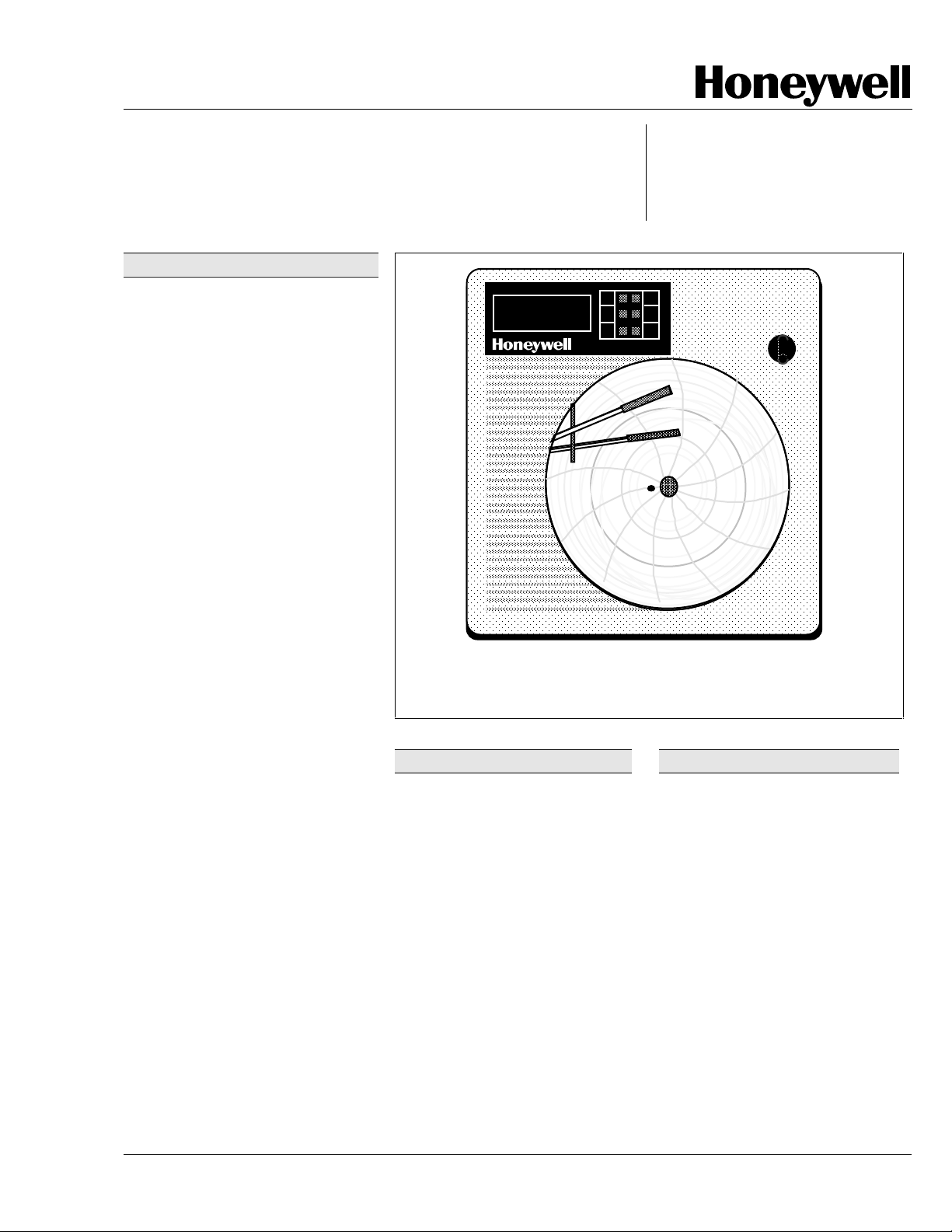
DR4300
Circular Chart Recorder
Function
The DR4300 Circular Chart Recorder
provides one of the most costeffective solutions for dependable
pen drawn analog traces on a 10-inch
(250 mm) chart.
It is easy to set up and configure to
match a wide range of applications
such as food processing,
environmental monitoring, machine
monitoring, flow, water and waste
monitoring, for use on furnaces and
ovens, packaging machines, and
numerous other processes.
The DR4300 Recorder gives you the
flexibility to tailor the recorder to
match any application, from basic
recording to actually doing the
process control, by choosing the
options that are required to
accomplish your application needs.
Both one- and two-pen models
accept inputs from any one of a
variety of sensors or transmitters
within the configurable range limits.
The DR4300 can be specified with
a variety of options such as one or
two digital controllers, a vacuum
fluorescent display for viewing the
process variable or configuration
using English language prompts.
You can also select Modbus
communications, or choose a
number of software options such
as a timer function, setpoint
programming, or advanced fuzzy
tuning/PID control.
™Modbus is a trademark of AEG Modicon
Figure 1—DR4300 Recorder provides clear analog trace and digital
indication of process variable value.
Charts—Over 200 preprinted
charts available to meet specific
recording needs.
Ink Cartridge—Disposable fibertip ink cartridge for dependable
recording with minimum
maintenance.
Universal Power—Eliminates the
concern with matching the local
power requirements.
Universal Inputs—Accepts 10
thermocouple types, RTDs, mA,
mV or voltage inputs through
simple configuration.
Thermocouple Failsafe—
Configurable upscale or downscale burnout.
ALM
F
4300
CHN
1
RSP
OUT
SP 4300
Features
1559
SET
UP
F
DISP
%
▲▼
44-01-03-04
Page 1 of 12
Specification
FUNC
MAN
AUTO
24155
Features, continued
Manual/Automatic Modes—
Bumpless, balanceless transfer
between control modes on
advanced recorders.
User Configurable—Allows you
to set up or alter operating parameters to fit your requirements.
Easily set DIP switch configuration
on basic recorder.
A Vacuum Fluorescent Display/
Keypad with English language
prompts is available for more
advanced recorder set up and
monitoring.
Optional Outputs—Choose from
Alarm, On-Off Control, Limit
Control, or versatile PID digital
controller.
3/01
Sensing and Control, 11 West Spring Street, Freeport, Illinois 61032
Printed in U.S.A. ■ © Copyright 2001—Honeywell
Page 2

44-01-03-04
Page 2
Features, continued
Accutune II™—Provides a new,
truly plug and play tuning
algorithm, which will, at the touch
of a button or through a digital
input, accurately identify and tune
any process including those with
deadtime and integrating
processes. This speeds up and
simplifies start-up plus allows
retuning at any setpoint.
Fuzzy Logic—This new feature
uses fuzzy logic to suppress
process variable overshoot due to
SP changes or externally induced
process disturbances. It operates
independently from Accutune
tuning. It does not change the PID
constants, but temporarily modifies
the internal controller response to
suppress overshoot. This allows
more aggressive tuning to co-exist
with smooth PV response. It can
be enabled or disabled depending
on the application or the control
criteria.
Individual Pen Options—Include
Totalization, a Timer function,
Digital Inputs, Auxiliary Output,
and Setpoint Programming
allowing the most flexibility to meet
the application need.
Quality/Support—The DR4300 is
backed up by a toll-free phone
number for technical assistance.
CE Mark—Conformity with
73/23/EEC, Low Voltage Directive
and 89/336/EEC, the EMC
Directive.
Options
Control Outputs—One or two
control outputs, PID-A, ON-OFF,
or PD with Manual Reset.
Solid State External Control
Relay Outputs—Optional outputs
rated at 2 Amps at 120/240 V or 10
Amps at 120/240 V. Minimum load
is 0.1 Amp.
Options, continued
Auxiliary Output—There is also
a 4 mA to 20 mA current output
available. If not used for control, it
can be used to retransmit a
process variable.
Digital Inputs—Two digital inputs
for each pen channel are
available. These inputs can be
used to trigger the switchover to a
second control setpoint or a preconfigured constant output if an
external event causes contact
closure. In addition, the digital
inputs can be used to remotely
reset the optional tolalizer or Limit
Controller or set up as a trace.
Alarm Selection—None, one, or
two relays to activate external
equipment when preset high/low
setpoints are reached.
Modbus
Allows you to network your
recorders to take advantage of
overall monitoring of the system
using an RS485 network.
Ramp Soak Programming—
Allows configuration of up to four
setpoint programs using a total of
twenty-four ramp and soak
segments. Run or Hold of
program is keyboard or remote
switch selectable.
Totalizer—Totalizes a variable,
such as a flow signal, on one or
both pens. Provides a 6-digit
digital display indication of the
totalized value with reset
capability. Totalizer allows the
units of the totalized value to be
different than the input units. A
low value cutoff value can also be
programmed for the totalizer.
Limit Control—This model
provides a latching relay that
activates whenever the PV goes
above (High Limit) or below (Low
Limit) a preset setpoint value. An
alarm message will be displayed
when the output is activated.
Reset is through a key on the
front of the recorder or an
optional
Communications—
Options, continued
external switch. Only FM
approved limit Control is available.
In addition to this, the second
relay output is available for an
alarm or as a timer output.
Timer—Provides a configurable
time period of 0 to 99 hours, 59
minutes. Alarm 1 is dedicated to
be active at the end of the timeout period. Timer “start” is
selectable as either the
RUN/HOLD key or Alarm 2. The
optional Digital Input can also be
configured to start the Timer in
addition to either the keyboard or
Alarm 2. The Timer display is
selectable as either time
remaining or elapsed time.
Transmitter Power—24 Vdc
transmitter output to power up to
two transmitters.
Door Options—Choice of gray,
blue, or black door with standard
latch or optional lock. Standard
acrylic window.
Approvals—UL, CSA, or
combined UL/CSA, FM Approved
Limit Controller.
Digital Controller
The DR4300 Recorder is available
with an integral microprocessorbased single-loop PID controller
for each pen.
A variety of output types—current,
time proportional simplex or
duplex control, with
electromechanical relays, solid
state relays, or open collector
outputs are available.
Depending on the output type,
users can configure the control
action as ON-OFF, PID-A, or PD
with Manual reset.
The recorder’s display and keypad
allows the user to quickly view
what is happening with the
process and to easily make
changes, and with the door
keypad these changes can be
made without opening the
recorder door.
Page 3

44-01-03-04
Page 3
Outputs
The following output types are
available per the model selection
guide:
• Electromechanical Relay
• Solid State Relay
• Open Collector Output
Output Algorithms
The DR4300 is available with the
following output algorithms:
Relay Simplex—Provides On-Off
or Time Proportional (relay)
output. Electromechanical, solidstate or open collector outputs
are standard; 2 amp or 10 amp
externally mounted solid-state
relay outputs are optional. One
output available for alarm.
Relay Duplex (Heat/Cool)—
Depending on which control
algorithm you select, this duplex
output type can provide on-off
duplex or time proportional
duplex. The time proportional
duplex output provides independent PID tuning constants and
two time proportional outputs:
one for heat zone above the
50 % output, and one for cool
zone below 50 % output.
Alarming is not available
Current Simplex—Supplies
proportional direct current output
for final control elements that
require a 4 mA to 20 mA signal.
Both relay outputs are available
for alarm.
Current/Relay Duplex
(Relay = Heat)—Type of output
using one relay for time proportional output for Heat control if PV
is greater than SP and one 4 mA
to 20 mA signal for cooling
control if PV is less than SP.
Relay/Current Duplex
(Relay = Cool)— Type of output
using one 4 mA to 20 mA signal
for Heat control if PV is greater
than SP and one relay for time
proportional output for cooling
control if PV is less than SP.
Control Algorithm
Depending on the output algorithm
you select, the recorder can be
configured for the following control
algorithms:
On-Off—Whenever the controlled
variable deviates a predetermined
amount from the setpoint, the
recorder moves the final control
element to either of two extreme
positions. Hysteresis: 0 % to 100 %
PID-A—The recorder gives full
response to Setpoint and Process
Variable (PV) changes involving
Gain (Proportional), Reset
(Integral), and Rate (Derivative)
effects. There is a fixed relationship
between the value of the controlled
variable and the position of the final
control element. The adjustable
Gain, Rate, and Reset Time tuning
constants let you tailor the
recorder’s response to your
process requirements.
PD with Manual Reset—The
action is similar to the PID-A
algorithm except the reset (Integral)
value is entered as Manual Reset
tuning constant instead of Reset
Time. The manual reset value
eliminates offset by shifting the PD
calculated output upscale or
downscale to return the recorder
variable to the setpoint.
Microprocessor Controlled
Recording
Both the chart and the pen are
driven by stepper motors controlled
by the microprocessor for precise
operation. This allows for
configurable chart speeds without
the need to change motors or
gears. The microprocessor uses
the configured range selection and
input data to determine the proper
pen position and then accurately
positions the pen to the correct
chart position without the need for
slidewire feedback or drive cables.
This provides for accurate and
reliable data recording.
Operator
Interface/Configuration
Since microprocessor control
replaces the previous electromechanical recording
mechanisms, the configuration of
the recorder is determined
primarily by its software.
For the basic recorder the
configuration is easily set up by
selecting the pre-configured
range, actuation, and chart
speed.
An optional display, using English
language prompts, provides
additional flexibility to select other
chart ranges, input actuation,
control or alarm parameters,
chart speeds, plus other software
features.
An upper and lower display
allows the user to view the
process variable (PV) and, by key
selection, the control setpoint,
control output, deviation from
setpoint, totalizer, Setpoint
Programming operation
information, time remaining or
elapsed time on the timer and the
status of Accutune, as desired.
In the Setup mode, digital
displays are preempted by
prompts and values for entering
the configur-ation data. Indicators
light to show which input channel
PV is being displayed, which
output relay is active, the
selected temperature unit, and
the recorder’s mode of operation.
The configuration data and
display actions are selected using
an integral keypad.
An optional keypad on the door
allows changes without the need
to open the door of the recorder.
The display can also be set to
toggle between Input 1 and Input
2. The display can also be set to
blank (turn off) if the operator
does not want to see a displayed
value.
Page 4

44-01-03-04
Page 4
Input Processing
The input can be one of any
standard low-level electrical
signals which can be selected by
the user.
Ranges are either pre-configured
or, by using the display/keypad,
expanded and compressed within
the range limits to meet the
specific measurement needs.
Users can select upscale or
downscale break protection for
most actuations.
Input samples are taken at a rate
of once every 0.33 seconds. Each
input is isolated from the other to
insure that the signals do not affect
the other inputs.
A digital filter value of 1 second on
the basic recorder provides input
signal smoothing or with the
display, this can be changed from
0 seconds to 120 seconds of
filtering to match the application
need.
The basic recorder provides a
wide selection of linear and nonlinear inputs for the user to select
which one best meets the need.
By adding the display, a full range
of selections is available to the
user. The non-linear inputs can be
set so the microprocessor
linearizes the input, thus allowing
mixed input actuations for two pen
models to record the process
variable on a linear chart. This can
be bypassed by recording on a
non-linear chart.
Control Modes
The recorder can operate in the
following modes:
Manual Mode—when switched to
manual mode, the recorder holds
its output at the last value used
during automatic operation and
stops adjusting the output for
changes in process variable.
Local Automatic Mode—The
recorder uses the local setpoint
and automatically adjusts the
output to maintain the setpoint at
the desired value.
Diagnostics
Each DR4300 has built-in
diagnostics that check critical
recorder operations and provide
error detection or messages to
alert the user of potential faults.
This self test is run each time the
recorder is powered up.
In addition to this, a built-in step
pattern test can be run on
demand to insure proper pen and
chart drive motor operation; this
draws a special test pattern on
the chart thus providing a record
of the recorder’s proper
operation.
Construction
All DR4300 recorders are
manufactured with a rugged,
durable, molded case designed to
withstand most industrial
environments. This case and the
standard NEMA 3 door are
designed to protect the internal
electrical components from harsh
industrial environments. The
recorder comes standard with an
acrylic window.
Knockouts in the side and bottom
of the case accept conduit
connections for convenient wire
entry of power, inputs, and
outputs. Individual boards for each
input allow the user to easily
service each input separately, add
an additional input to a single pen
recorder and to avoid problems
with isolation of each signal.
The removable connectors also
allow for easier servicing without
having to disconnect the field
wiring.
Page 5

Specifications
Performance
44-01-03-04
Page 5
Number of Inputs
One pen model: One input
Two pen model: Two inputs
REFERENCE ACCURACY
Types of Input
Actuations
Thermocouples
B 105 to 3300
E –454 to 1832
E (low) –200 to 1100 –129 to 593 1.0 0.6 11 6 0.40
J 0 to 1600 –18 to 871 1.6 0.9 7 4 0.15
J (low) 20 to 770 –7 to 410 0.8 0.5 6 3 0.08
K –320 to 2500 –196 to 1371 2.4 1.4 9 5 0.15
K (low) –20 to 1000` –29 to 538 1.0 0.6 7 4 0.10
Ni-Ni Moly 32 to 2500
Nicrosil-Nisil 0 to 2372 –18 to 1200 2.1 1.2 11 6 0.20
R 0 to 3100
S 0 to 3100
T –420 to 700 –251 to 371 1.6 0.9 13 7 0.15
T (low) –200 to 600 –129 to 316 0.8 0.5 7 4 0.15
W5W26 0 to 4200
RTD
Platinum
100 ohms**
100 ohms
(low)**
100 ohms (T)***
150 to 500
500 to 1000
1000 to 3300
–454 to –202
–202 to 1832
32 to 500
500 to 2500
0 to 500
500 to 3100
0 to 500
500 to 3100
0 to 600
600 to 3600
3600 to 4200
–300 to 900
–130 to 392
–238 to 482
Range Reference Accuracy*
with
Field Calibration
°F °C± °F± °C± °F± °C Per 1 Degree •T
41 to 1816
66 to 260
260 to 538
538 to 1815
–270 to 1000
–270 to –130
–130 to 1000
0 to 1317
0 to 260
260 to 1371
–18 to 1704
–18 to 260
260 to 1704
–18 to 1704
–18 to 260
260 to 1704
–18 to 2316
–18 to 316
316 to 1982
1982 to 2316
–184 to 482
–90 to 200
–150 to 250
28.0
6.0
3.0
36.0
2.0
1.5
1.0
4.0
2.0
4.0
2.0
2.8
2.6
3.2
0.8
0.6
0.6
16.0
3.3
1.7
20.0
1.1
0.8
0.6
2.2
1.1
2.2
1.1
1.6
1.5
1.8
0.5
0.3
0.3
Reference Accuracy*
with
Factory Calibration
37
18
79
14
12
9
26
13
23
13
19
13
27
4
3
3
21
10
44
8
7
5
14
7
13
7
11
7
15
2
2
2
Temp Stability
± Degrees
Error
4.00
1.00
0.40
1.40
0.70
0.21
0.14
0.50
0.21
0.50
0.21
1.00
0.50
0.20
0.15
0.15
0.15
*Includes reference junction calibration of ± 0.01 degrees using the standard "ice bath" method of calibration. Factory
calibration at reference ± 1.2 °F. Note that factory calibration may have typical variations of ± 150 microvolts or ± 0.6 ohms
for RTDs which means recalibration may be required to achieve stated accuracy.
**IEC Alpha = 0.00385
***Alpha = 0.00391
NOTE: Field Calibration requires model with display.
Page 6

44-01-03-04
Page 6
Specifications, continued
Performance, continued
REFERENCE ACCURACY
Types of Input
Actuations
Linear
Milliamperes dc
Millivolts dc 0 to 10
Volts dc 0 to 1
Range Reference Accuracy*
with
Field Calibration
0 to 20
4 to 20
0 to 100
0 to 200
0 to 2
0 to 5
1 to 5
0 to 10
16 µA
16 µA
10 µV
100 µV
200 µV
1 mV
2 mV
5 mV
4 mV
10 mV
Reference Accuracy*
with
Factory Calibration
80 µA
80 µA
50 µA
500 µA
1.0 mV
5 mV
10 mV
25 mV
20 mV
50 mV
Design
Minimum Input Span Range is fully configurable within span limitation of the sensing element.
Input Impedance mA dc: 250 ohms
Vdc: 200 K ohms
RTD: 13.3 K ohms
All Others: 10 Megohms
Temp Stability
± Degrees
Error
Per 1 Degree
0.011 %/°F
0.011 %/°F
0.011 %/°F
0.011 %/°F
0.011 %/°F
0.011 %/°F
0.011 %/°F
0.011 %/°F
0.011 %/°F
0.011 %/°F
•T
Span Step Response
Time
Reproducibility 0.1 percent of span
Sampling Rate Input sampled every 1/3 seconds
Input Filter Without Display: Analog with time constant of 3 seconds and digital with time constant of 1
Digital Displays
(Optional)
Modes of Operation Manual
*Includes reference junction calibration of ± 0.01 degrees using the standard "ice bath" method of calibration. Factory
calibration at reference ± 1.2 °F. Note that factory calibration may have typical variations of ± 150 microvolts or ± 0.6 ohms for
RTDs which means recalibration may be required to achieve stated accuracy.
7 seconds maximum
second.
With Display: Analog with time constant of 3 seconds and digital adjustable 0 seconds to 120
seconds.
Vacuum fluorescent, alphanumeric
An upper four-digit display dedicated to the process variable or setpoint.
Alternate information displayed during configuration.
A six-digit lower display shows key selected operating parameters. Also provides guidance
during configuration.
Automatic with local set point
Page 7

Specifications, continued
Design, continued
Indicators Channel PV display (INP 1 or 2)
Controller output (OUT 1 or 2)
Temperature unit (F or C)
Controller’s mode (A or M)
Active Setpoint [L = SP1 active; R = SP2(S2) active]
Controller Output On-Off or Time Proportional
One SPDT electromechanical relay. Control action can be set for direct or reverse.
For Limit Controller: SPDT electromechanical output.
Electromechanical Relay Contact Ratings:
Resistive Load: 5 A @ 120 Vac, 2.5 A @ 240 Vac
Inductive Load: 50 VA @ 120 Vac or 240 Vac
Solid State Relay Contact Rating: 0.8 A @ 120 Vac
Open Collector Output Contact Rating: 12 mA @ 24 Vdc
Time Proportional Relay Resolution: 3.33 mSec.
Cycle Time: 1 second to 120 seconds
Current Proportional
21 mA dc maximum into a negative or positive grounded or non-grounded load of 0
ohms to 600 ohms. Output range can be set between 4 mA and 20 mA, and as direct or
reverse action.
Resolution: 11 bits
Accuracy: 0.5 % Full Scale
44-01-03-04
Page 7
Time Proportional Duplex
Variation of time proportional for Heat/Cool applications. Uses two relay contacts with
adjustable deadband that is split at 50 % controller output.
Current Duplex and Time/Current Duplex
Variation of time proportional duplex for Heat/Cool applications. Time proportional
output (heat or cool) is a SPST relay. Current proportional output (heat or cool) is a 4
mA to 20 mA signal that can be fed into a negative or positive grounded load of 0 ohms
to 600 ohms and is operational over 50 % of range or the entire range.
Time Proportional Relay Resolution: 3.33 mSec.
Relay Contact Ratings:
Resistive Load: 5 A @ 120 Vac, 2.5 A @ 240 Vac
Inductive Load: 50 VA @ 120 Vac or 240 Vac
Cycle Time: 1 second to 120 seconds
Current Proportional:
Resolution: 11 bits
Accuracy: 0.5 % full scale
Action
Direct or Reverse
Output Limits
0 % to 100 % Relay Output
–5 % to 105 % Current
Deadband
–5 % to 25 % Time Relay
0 % to 25 % On-Off Duplex
Hysteresis
0 % to 100 % of PV span
Case Molded, foamed-Noryl* with gasketed door to meet NEMA 3 enclosure requirements.
*Registered Trademark — General Electric Co.
Page 8

44-01-03-04
Page 8
Specifications, continued
Design, continued
Pen Disposable fiber-tip ink cartridge, line length per cartridge more than 1000 ft (305 m)
One Pen: Purple
Two Pen: Purple (pen one) and red (pen two)
NOTE: Only pen 1 (purple) is referenced to the chart time line.
Chart 10.24-inch (260 mm) diameter chart with standard preprinted markings and a calibrated
width of 4 inches (100 mm).
Wiring Connections Two piece wiring connectors inside case.
Color Case: Black
Door: Gray (standard); Caribbean blue (optional)
Window: Acrylic
Approval Bodies CE Mark, UL, CSA, FM Approved Limit Controller
Dimensions See Figure 2.
Weight 12 lb. (5.4 kg)
Mounting Panel, surface, or 2-inch pipe mounting
CE Conformity (Europe)
(Optional)
Product Classification:
Enclosure Rating:
Installation Category (Over-voltage
Category)
Pollution Degree:
EMC Classification
Method of EMC Assessment
Declaration of Conformity
This product is in conformity with the protection requirements of the following European
Council Directives: 73/23/EEC, the Low Voltage Directive, and 89/336/EEC, the EMC
Directive. Conformity of this product with any other “CE Mark” Directive(s) shall not be
assumed.
Class I: Permanently Connected, Panel Mounted Industrial Control Equipment with
protective earthing (grounding). (EN 61010-1)
Panel Mounted Equipment, IP 00, this recorder must be panel mounted.
Terminals must be enclosed within the panel. Front panel IP 65 (IEC 529)
Category II: Energy-consuming equipment supplied from the fixed installation.
Local level appliances, and Industrial Control Equipment. (EN 61010-1)
Pollution Degree 2: Normally non-conductive pollution with occasional conductivity
caused by condensation. (Ref. IEC 664-1)
Group 1,Class A, ISM Equipment (EN 55011, emissions), Industrial Equipment (EN
50082-2, immunity)
Technical File (TF)
51197639-000
Page 9

Specifications, continued
Options
44-01-03-04
Page 9
Alarm Output Two SPDT electromechanical relays, or solid state or open collector outputs for an
Tuning PID tuning parameters of Gain or PB, Rate, Reset.
Chart For Basic Recorder chart speeds set as part of configuration for 8 hours, 12 hours,
Input Display can be set for 0, 1 (XXX.X) or 2 (XX.XX) decimal position with Display/Keypad,
Sensor Burnout Selectable for None, Up, or Down.
Totalizer (Optional) Totalizers (1 per pen); 6 digits displayed; resettable with Keypad or remote (digital)
Alarms Type: Based on PV or deviation, high or low state
Digital Inputs Two digital inputs, dry contact
Through the Door External
Keypad
Modbus Communication Baud Rate: 19,200 maximum
Setpoint Ramp/Soak
Programming (Optional)
alarm.
Relay Contact Ratings:
Resistive Load: 5 A @ 120 Vac or 2.5 A @ 240 Vac
Inductive Load: 50 VA @ 120 Vac or 240 Vac
24 hours or 7 days; with Display/Keypad speeds selectable from 1 hour to 744 hours.
°F or °C units.
Input range can be scaled from –999 to 9999 and bias of –999 to 9999.
input; rate can be set for seconds, minutes, hours, days, or millions per day, scale factor
by 10’s from 1 to 1 x 10⁸; programmable low flow cutoff value.
Hysteresis: 0 % to 100 % of input span
Use for Event Recording, Reset Totalizer, Timer, Switch to Setpoint 2, Switch to Manual
mode.
Six-button keypad to allow operator selections without opening the door.
Protocol: Modbus
Length of Link: 4,000 ft (1,219 m) maximum
Link Characteristics: Two-wire, Multidrop
Allows configuration of up to four setpoint programs using a total of twenty-four
ramp and soak segments.
Run or Hold of program is keyboard or remote switch selectable.
Each ramp segment can be configured to be run in Hours and Minutes or degrees per
minute.
Soak segments can have a guaranteed soak deviation which guarantees the time for
each soak and will not start until the PV is reached.
Timer Configurable time period of 0 to 99 hours, 59 minutes.
Alarm 1 is dedicated to be active at the end of the time-out period.
Timer “start” is selectable as either the RUN/HOLD key or Alarm 2.
The optional Digital Input can also be configured to start the Timer in addition to either
the keyboard or Alarm 2.
The Timer display is selectable as either time remaining or elapsed time.
Transmitter Power 24 Vdc with adjustment of ± 6 % (22.6 to 25.4)
100 mA maximum output
Page 10

44-01-03-04
Page 10
Specifications, continued
Environmental and Operation Conditions
Parameter Reference Rated Extreme Transport and
Storage
Ambient Temperature 67 °F to 77 °F
Relative Humidity (% RH) 50 ± 3* 10 to 90* 5 to 90* 5 to 95*
Vibration
Frequency (Hz)
Acceleration (g)
Mechanical Shock
Acceleration (g)
Duration (ms)
Mounting Position from Vertical
Tilted Forward
Tilted Backward
Tilted to Side (±)
Power Requirements
Voltage (VRMS)
Frequency (Hz)
Power Consumption 20 watts maximum
*The maximum rating only applies up to 104 °F (40 °C). For higher temperatures, the RH specification is derated to maintain
constant moisture content.
**122 °F (50 °C) is maximum temperature for recorder with UL Listing.
19 °C to 25 °C
0
0
0
0
5°
5°
5°
120 ±1 or 240 ±1
60 ±0.21 or
50 ±0.21
58 °F to 131 °F
15 °C to 55 °C**
0 to 70
0.1
1
30
5°
30°
10°
100 to 240
60 ±1 or 50 ±1
32 °F to 131 °F
0 °C to 55 °C**
0 to 200
0.5
5
30
5°
90°
20°
90 to 264
48 to 62
–40 °F to 151 °F
–40 °C to 66 °C
0 to 200
0.5
5
30
Any
Any
Any
N/A
N/A
N/A
General Reference Data
Stray Rejection Common Mode Rejection Ratio: 120 dB or 1 LSB (whichever is greater) at 60 Hz with
maximum source impedance of 100 ohms.
Normal Mode Rejection Ratio: 60 dB with 100 % span peak to peak maximum at 60 Hz.
Static Charge Effects Exposed panel surface capable of withstanding a discharge from a 250 pf capacitor
charged to 10 KV through 100 ohms.
RFI Susceptibility Capable of withstanding an EMI-field generated from a 5-watt transmitter being held at
1 meter, and operating at 151.685 and 450 MHz.
Line Noise Effects Field terminals for connecting power line to recorder can withstand the IEEE Surge
Withstanding Capability Test to level of 2.5 KV.
Technical Assistance Toll-free 800 number puts technical assistance only a phone call away.
Page 11

Dimensions
44-01-03-04
Page 11
ALM
F
1
80 .8
CHN
1
RSP
INP 1
L
Front View
F
%
355.6
14.0
322.5
12.70
Panel
Cutout
355.6
14.0
322.5
12.70
Left Side View
23
0.9
320.5
12.6
147.8
5.8
Short wing latch :
Double bit latch :
14.5
.57
5
.19
41.3
1.6
Latch
163.2
6.4
Bottom View
320.5
12.6
Rear View
369.6
14.5
Surface
Mounting
17.5
0.6
196.2
7.7
181.3
7.1
24154
Figure 2—DR4300 Recorder Dimensions—For Reference Only
Page 12

44-01-03-04
Page 12
Ordering Information
For complete ordering information, request Model Selection Guide
44-01-16-04 for DR4300 Circular Chart Recorder.
For more information, contact Honeywell sales at (800) 343-0228.
Specifications are subject to change without notice.
Distributor :
WARRANTY/REMEDY
Honeywell warrants goods of its manufacture as being free of defective materials and faulty workmanship. Contact your local
sales office for warranty information. If warranted goods are returned to Honeywell during the period of coverage, Honeywell
will repair or replace without charge those items it finds defective. The foregoing is Buyer’s sole remedy and is in lieu of all
other warranties, expressed or implied, including those of merchantability and fitness for a particular purpose.
Specifications may change without notice. The information we supply is believed to be accurate and reliable as of this
printing. However, we assume no responsibility for its use.
While we provide application assistance personally, through our literature and the Honeywell web site, it is up to the customer
to determine the suitability of the product in the application.
Sensing and Contr ol
Honeywell
11 West Spring Street
Freeport, IL 61032
44-01-03-04 0301 Printed in USA www.honeywell.com/sensing
 Loading...