

Page 1

Parts List
9. Parts List
9.1 Overview
Introduction
This section provides the replacement parts lists for the DR4300 Circular Chart Recorder.
Most parts are supplied on an optimum replacement unit basis; that is, part numbers are given for complete
printed circuit assemblies rather than for individual PCA components.
The figures that follow are exploded views of the DR4300 recorder. Each part is labeled with a key number
and the key numbers are listed in tables with associated part numbers.
When ordering parts, be sure to specify your recorder’s serial and model numbers (on chartplate) as well as
the part number.
Also included for your reference are an Internal Cabling drawing (Figure 9-4) and an Internal Wiring
Diagram (Figure 9-5) for options only.
What’s in this section?
The following is a list of the topics covered in this section.
Topic See Page
9.1 Overview 191
9.2 Exploded Views
Figure 9-1 Door Assembly
Figure 9-2 Chart Plate
Figure 9-3 Recorder Components
9.2 Internal Cabling
Figure 9-4 Internal Cabling CE Mark Version
Figure 9-5 Internal Cabling Non-CE Mark Version
192
192
193
194
196
197
1/06 DR4300 Circular Chart Recorder Product Manual 191
Page 2
DR4300 Circular Chart Recorder
9.2 Exploded Views
Door assembly
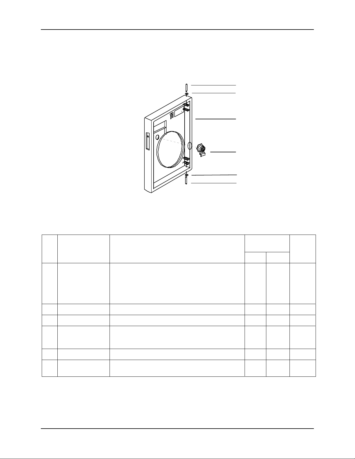
Figure 9-1 is an exploded view of the door assembly. Table 9-1 is a list of the associated part numbers.
1-1
1-2
1
1-3
1-2
1-1
24187
Key
1
1-1
1-2
1-3
(K)30756409-002 Hinge Pin* 2
(K)30756409-002 Retaining Ring* 2
Part Number
51309609-501
51309609-502
51309609-506
51404778-501
51309609-503
51404673-501
30757307-503
51198139-501 Graphic Overlay for Door* (not shown) 1
51309609-504 External Keypad Assembly Replacement Kit* (not
Door Assembly (includes components for all door
variations)
Gray Door
Blue Door
Black Door
NEMA4/Heavy Duty Door
Latch/Lock Assembly Kit*
NEMA4/Heavy Duty Door Latch/Lock Assembly Kit*
Key Only for Lock Assembly*
shown)
Figure 9-1 Door Assembly
Table 9-1 Door Assembly Parts
Description
Recommended
Spare Parts Per
10 100
1
1 3 1
1
Quantity
per Unit
*Parts included with applicable door assembly.
(K) denotes that the part number is for the parts kit in which the described part is included. The described
part cannot be ordered separately.
192 DR4300 Circular Chart Recorder Product Manual 1/06
Page 3
Parts List
Chart plate
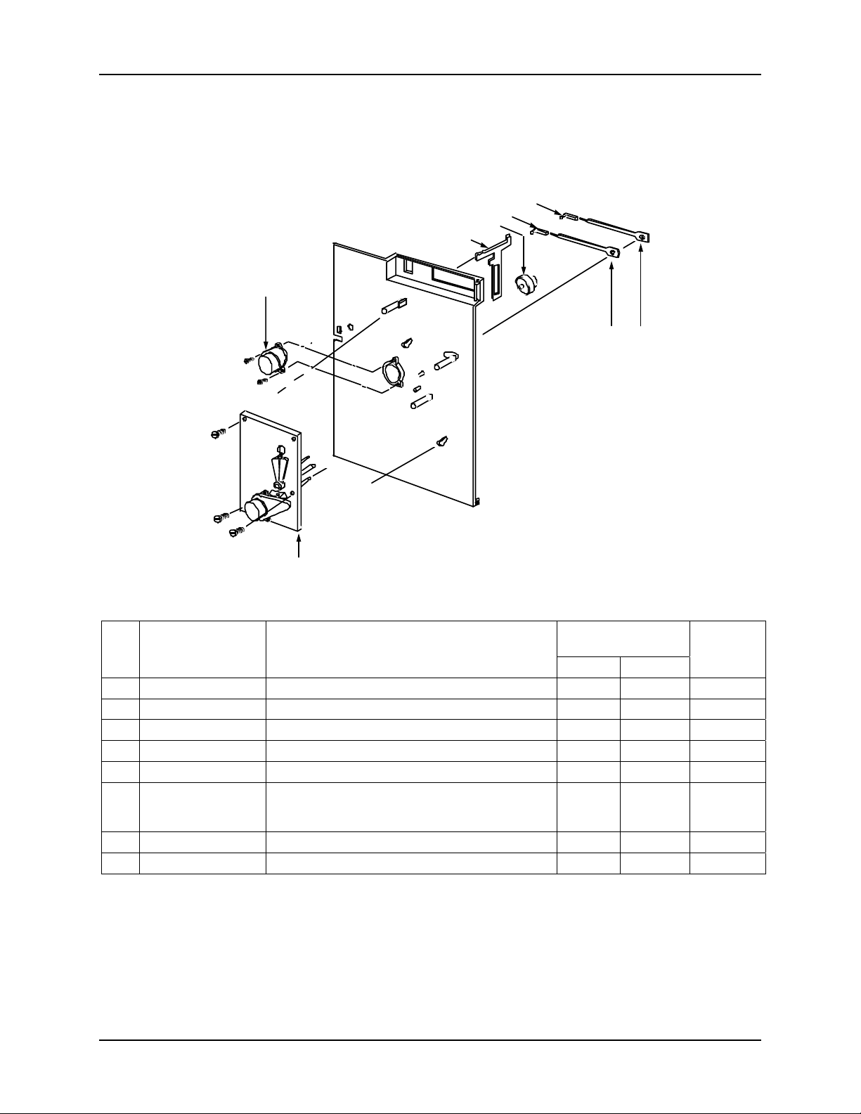
Figure 9-2 is an exploded view of the chart plate assembly. Table 9-2 is a list of the associated part
numbers.
3
4
7
8
5
1
2
24215
6
Figure 9-2 Chart Plate Assembly
Table 9-2 Chart Plate Assembly Parts
Key
(K)30756409-002 No. 1 Pen Arm 1 5 1
1
(K)30756409-002 No. 2 Pen Arm (2-pen model only) 1 5 1
2
3
4
5
6
(K)30756150-501 Chart Hub Kit 1
7
(K)30756409-002 Pen Lifter Retainer 1
8
Part Number
Description
Recommended
Spare Parts Per
Quantity
per Unit
10 100
30735489-007 No. 1 Purple Pen Cartridge (six pack) 1 3 1
30735489-002 No. 2 Red Pen Cartridge (six pack) 1 3 1
30756113-501 Chart Motor 1 3 1
30755833-501
30755833-502
Servo Plate Assembly
1-pen model
2-pen model
1
(K) denotes that the part number is for the parts kit in which the described part is included. The described part
cannot be ordered separately.
1/06 DR4300 Circular Chart Recorder Product Manual 193
Page 4

DR4300 Circular Chart Recorder
Basic recorder components without options
Figure 9-3 is an exploded view of the recorder. Table 9-3 is a list of the associated part numbers.
5
1
2
3
4
24090A
Figure 9-3 Recorder Components
194 DR4300 Circular Chart Recorder Product Manual 1/06
Page 5

Parts List
Table 9-3 Basic Recorder Parts
Key Part Number
1
2
3
4
5
Parts Not Shown
51404459-501 Display Module Printed Circuit Assembly 1 3 1/2
51404999-001 Hand Held Display Kit
51197612-502 Round cable suppression cores, package of 2 1 3 up to 3
51197612-508 Round cable suppression cores, package of 8 1 1 1
51198150-501 Pipe Mounting Kit, 2 inch size
30755306-501 Relay Kit - Electromechanical 1 10 2
30756725-501 Relay Kit - Solid State 1 10 2
30756679-501 Relay Kit - Open Collector 1 10 2
51204403-501 Transmitter 24 V Power Supply Assembly
51404753-501 Filter assembly, CE version
51404546-501 Battery for Totalizer Option
30755065-001 Standard Mounting Bracket Kit
30755065-502 Heavy Duty/NEMA4 Mounting Bracket Kit
51197657-501 Panel Mount Gasket Kit
51205804-501 Terminal Block Kit
Upgrade PROMs
51197993-501 Basic Recorder PROM, latest software version
51450899-501 Totalizer Upgrade PROM and Battery
51450899-502 PID Control Upgrade PROM
51450899-503 Auxilary Output/Timer Upgrade PROM
51404453-501
51404453-502
51404453-505
30755800-502 Case 1 3 1
51404511-501 Cable Replacement Kit 1 3 1
51404566-501 Digital Input Assembly 1 3 1/2
51404750-502 Modbus Communication Assembly 1 3 1/2
100 Vac to 240 Vac models
Printed Circuit Assembly, Record Only
Printed Circuit Assembly, Record and Control Spare Kit
(includes solid state relay and open collector output)
Printed Circuit Assembly, FM-approved Limit Controller
(includes solid state relay and open collector output)
Description
Recommended
Spare Parts Per
10 100
1
3
Quantity
per Unit
1/2
1/06 DR4300 Circular Chart Recorder Product Manual 195
Page 6

DR4300 Circular Chart Recorder
Chart
Plate
Chassis Ground for RS485/422
Communication Card-
51404880-001
Chart Motor
5 conductor cable-
51404677-001
J1
Battery
P1 P2 P3 J1 J3
TB1 TB1
Display /
Keyboard
Pen 1
Pen 2
Pen 2 Motor
Pen 1 Motor
Pen 1 Motor
J4
RS485/422
Communication Card
J10 J10
Digital Input C ab le-
51404586-001
12 conductor flat flexible cable- 51309650-002
12 conductor flat flexible cable-
51309650-001
Ground cable- 30755062-008
4 cond u c to r p e n motor cab le
4 cond u c to r p e n motor cab le
4 cond u c to r c h a rt motor cab le
24V Power Supply Cable- 51404588-001
AC
In
J2
P1 P2 P3
24V
Transmitter
Power Supply
J1 J3
J4 J4
Digital Input Ca b le-
51404586-001
Battery
Shield
Wire
P7
Power cable51309731-001
AC Supply
Pen 2
Mainboard
Digital Input Pow e r
Cable- 51404585-001
Digital Input Digital Input
J9
Digital Input Gro und Cable
Ground cable- 30755062-006
Voltage
Figure 9-4 DR4300 Recorder (CE Mark) – Internal Cabling Diagram
J13
Ground
Lug
P7
J9
Ground cable- 30755062-006
CE Ma rk F ilte r
Assembly-
51404753-001
Pen 1
Mainboard
J13
Digital Input Power
Cable- 51404585-001
Digital Input Ground Cable
196 DR4300 Circular Chart Recorder Product Manual 1/06
Page 7

Parts List
Chart
Plate
Chassis Ground for RS485/422
5 conductor cable-
51404677-001
Battery
2 Pen power
cable assembly
51309731-002
Display /
Keyboard
Communication Card-
51404880-001
Chart Motor
J1
J4
RS485/422
Communication Card
P1 P2 P3 J1 J3
J10 J10
Digital Input Cable-
51404586-001
TB1
Pen 2
Mainboard
Pen 1
Pen 2
Pen 2 Motor
12 conductor flat flexible cable- 51309650-002
12 conductor flat flexible cable-
Ground cable- 30755062-009
4 conductor pen mo tor cab le
Pen 1 Motor
Pen 1 Motor
4 conductor pen mo tor cab le
4 conductor chart motor c ab le
24V Power Supply Cable- 51404588-001
AC
Transmitter
In
J2
Power Supply
P1 P2 P3
J4 J4
Digital Input Cable-
51404586-001
TB1
Pen 1
Mainboard
J13
Shield
Wire
51309650-001
24V
Battery
J1 J3
J13
Digital Input Power
Cable- 51404585-001
Digital Input Ground Cable
Cable- 51404585-001
P7
Digital Input Digital Input
J9
Digital Input Grou n d C a ble
Ground cable- 30755062-006
TB6
Digital Input Power
Ground
Lug
NOTE:
P7
J9
Ground cable- 30755062-006
For 1 pen units, the 51404588-002 cable
assembly is used. For 2 pen units, the 51309731-002
AC Supply Voltage
connector
cable as se mbly is used.
Figure 9-5 DR4300 Recorder (Non-CE Mark) – Internal Cabling Diagram
1/06 DR4300 Circular Chart Recorder Product Manual 197
 Loading...