

Page 1

GR Series and DR Graphic Recorders
DR Graphic, Multitrend GR, Minitrend GR and eZtrend GR
See, Store and Send Data Securely
For the best in Display Versatility, Analysis and
Communications ..
choose
Page 2

ii 43-TV-25-41 Iss.4 GLO May 2015 UK
User manual
Page 3

Table of Contents
Section 1: Preface .............................................................................. 1
Preface ...........................................................................................................1
Thank you for choosing a Honeywell GR Series recorder ....................................... 1
Documentation.......................................................................................................... 1
Notes......................................................................................................................... 1
Trademarks............................................................................................................... 1
Safety ............................................................................................................. 2
Symbols..................................................................................................................... 2
Static Electricity........................................................................................................ 3
Protocols used in this manual ........................................................................ 3
Safety and Symbol Identification .............................................................................. 3
Warnings and Safety Precautions .................................................................. 3
Do’s and Don’ts......................................................................................................... 3
Hazardous Voltage.................................................................................................... 4
For use in hazardous locations................................................................................. 5
Section 2: Installation .........................................................................................7
Environment and Location ............................................................................ 7
Mechanical Installation .................................................................................. 8
Installation Instructions........................................................................................... 11
Electrical Installation ................................................................................... 22
Installation Category.............................................................................................. 22
Analogue Input Card.............................................................................................. 29
eZtrend GR Analogue Input (Standard) card.................................................. 32
Analogue Output Card............................................................................................ 33
Pulse Input Card..................................................................................................... 35
Transmitter Power Supply Card............................................................................. 37
Alarm Relay Cards & Digital Input/Output Cards................................................. 38
Communications Connections .............................. ... ............................. .. ................ 42
USB Devices ........................................................................................................... 44
Section 3: Overview ..........................................................................................45
Functions and Features ................................................................................ 45
Recorder Functionality........................................................................................... 47
Features.................................................................................................................. 49
Options - Hardware................................................................................................ 55
Section 4: Recorder Setup ................................................................................63
Power up ...................................................................................................... 63
1. Menu Access ....................................................................................................... 63
2. Log On/Off.......................................................................................................... 64
4. Time and Date Settings...................... .......................................................... .. ..... 65
5. Firmware Options.............. .......................................................... .. ..................... 65
Menu Path................. .......................................................... .................................... 65
Help ........................................................................................................................ 66
Configure Menu...................................................................................................... 67
Setup Menu ............................................................................................................. 68
Edit Recording...................................................................................................... 148
43-TV-25-41 Iss.4 GLO May 2015 UK iii
Page 4

Reports Menu........................................................................................................ 153
Layout .................... ............................. .................................................................. 157
Passwords.................................... ... ............................ .......................................... 164
Settings................. ................................................................................................. 173
Alarms Menu....................... ............................. ... ............................. .. ................... 175
Screen Menu.......................................................................................................... 176
Batch Setup/Batch Groups.................................................................................... 180
Recording Menu.................................................................................................... 184
Messages Menu..................................................................................................... 187
Process Menu.. ...................................................................................................... 190
Status Menu........................................................................................................... 194
Finish ..................... ............................................................................................... 206
Section 5:Security .......................................................................................... 207
Password Security................................................................................................. 207
Users and Groups................................................................................................. 207
Administrator............................................. ............................. .............................. 208
Password Policy.................................................................................................... 210
User Interface requirements ................................................................................. 210
Audit Trail..................... ....................................................................................... . 210
Level Permissions ................................................................................................. 211
Default Password Access...................................................................................... 214
Hardware Configuration Lock.............................................................................. 224
Section 6: Screen Configuration ................................................................... 225
Process Screen Overview................................. ..................................................... 225
Menu Bar .............................................................................................................. 226
Screen Menu Bar..................................................... .............................................. 227
Replay ............. ...................................................................................................... 228
Chart Speeds............................ ............................................................................. 235
Hot Button....................... .......................................................... .. .......................... 235
Screen Activity....................................................................................................... 236
Section 7: Firmware Options ......................................................................... 241
Firmware Credit System .............................................................................241
Firmware Options................................................................................ ................. 243
Section 8: Communication ............................................................................245
Comms Configuration ................................................................................245
Standard Communication Interfaces ..........................................................245
Protocols..................................................................... .......................................... 246
Hardware Installation .................................................................................247
Getting connected - IP Address ............................................................................ 248
Local Area Network setup..................................................................................... 249
Links to Remote Networks..................................... ................................................ 249
Data Logging and Transfer................................................................................... 249
Comms and Trend Manager Suite ..............................................................251
System Requirements........................................................ ..................................... 252
Software Installation............................................................................................. 253
Start Up................................................................................................................. 254
iv 43-TV-25-41 Iss.4 GLO May 2015 UK
Page 5

Communications Server .............................................................................258
Comms Server Overview ....................................................................................... 258
Comms Server Start up.......................................................................................... 258
Comms Server Setup.............................................................................................. 261
Comms Server Logging ......................................................................................... 266
Comms Server Database ............................................................................ 274
System Setup.......................................................................................................... 274
Shutdown Server ........................................................................................274
.Modbus Capabilities:.......... ................................................................................. 275
Web Browser ..............................................................................................276
Internet Security Settings ...........................................................................277
Section 9: PC Software Suite .........................................................................279
The TrendManager Pro Software Suite................................................................. 279
X Series & GR Recorder Screen Designer.......... .................................................. 279
Database Management Tool.................................................................................. 280
Report Generation Tool - AMS2750...................................................................... 280
System Requirements............................................................................................. 280
Section 10: Spares List ..................................................................................281
Minitrend GR Recorder......................................................................................... 281
Multitrend
eZtrend GR Recorder............................................................................................. 291
DR Graphic Recorder........................................................................................... 295
GR Recorder...................................................................................... 285
Section 11: Instrument Care and Maintenance ............................................ 301
Instrument Care and Maintenance .............................................................301
Cleaning Instructions................................. ... ............................. .. ......................... 301
Backlights.............................................................................................................. 301
Operating T emperature ......................................................................................... 301
Touch Screen.......................................................................................................... 302
Calibration ............................................................................................................ 302
Section 12: Technical Data & Specifications ...............................................303
Field IO Specification ................................................................................303
Analogue Input ...........................................................................................304
Relay Alarm/Digital Input Specification ....................................................304
Relay/Alarm Output Card Options........................................................................ 304
Digital Input Cards ............................................................................................... 305
Specification Tables................................................................................. .............. 307
Input Range Performance Accuracy Table............................................................ 312
Input Actuation
(Linear).................................................................................................................. 312
Input Actuation...................................................................................................... 313
LED Flash Codes .................................................................................................. 317
Appendix A: Quality and Safety ....................................................................319
CE Mark .....................................................................................................319
Safety ..........................................................................................................319
43-TV-25-41 Iss.4 GLO May 2015 UK v
Page 6

Appendix B: Maths Expressions ................................................................... 321
Full Maths & Script Processing .................................................................321
Maths Credit Options............................................................................................ 321
Maths Variable and Function Tables ............................................................ .. ...... 322
Full Maths............................................................................................................. 330
Script Function Application Examples ............ ..................................................... 331
Maths Error Messages................. ......................................................................... 336
Appendix C: Thermocouple Connections ....................................................337
How Thermocouples work .........................................................................337
Thermocouple CJC Compensation ............................................................. 338
Internal Automatic ...................................................................................... .. ........ 338
Ext 0°C Reference................................................................................................. 339
External with a Specified Temperature................................................................. 339
External Input Reference ................ ...................................................................... 340
Appendix D: Alarms .......................................................................................341
Alarms Menu....................... ............................. ... ............................. ..................... 341
Appendix E: Ethernet ..................................................................................... 343
Ethernet..... ............................................................................................................ 343
Email............... ....................................................................................... .. ............. 344
General operation of the e-mail system............................................. ................... 344
Appendix F: Fuzzy Logging ........................................................................... 345
Appendix G: F sub zero Sterilisation ............................................................ 349
The significance of F0........................................................................................... 349
Appendix H: Calibration ................................................................................. 351
AI Calibration and CJC Calibration ...........................................................351
Sensor Compensation .................................................................................351
Appendix I: Battery Data ................................................................................ 353
Location: Processor Board .........................................................................353
Safety Guidelines .................................................................................................. 353
Appendix J: Function Codes and Memory Maps ......................................... 355
Modbus Memory Map Supplement: ..........................................................355
Totalisers.............. ................................................................................................. 360
Input Text message................................................................................................ 360
Analogue Input Value............................................................................................ 360
Communications Input.......................................................................................... 360
Pen Values..................... ........................................................................................ 361
Modbus Function Codes .............................................................................362
Appendix K: Troubleshooting ....................................................................... 363
Error Messages ...........................................................................................363
vi 43-TV-25-41 Iss.4 GLO May 2015 UK
Page 7

Appendix L: GR Series AMS2750 capabilities ..............................................377
AMS2750 and the GR Series Recorders ................................................... 377
AMS2750 Process mode ............................................................................ 378
AMS2750 Credit Option....................................................................................... 378
AMS2750 Process Menu....................................................................................... 379
AMS2750 Process Screen..................................................................................... 379
SAT........................................................................................................................ 383
I/O + AMS2750 (Process Mode).......................................................................... 383
AMS2750 Button (Process Mode)......................................................................... 385
Pens for TC’s (Process Mode).............................................................................. 389
Thermocouple Usage Tracking (AMS2750)......................................................... 390
TUS mode ..................................................................................................392
Temperature Uniformity Survey (TUS) Mode....................................................... 392
AMS2750 (TUS) - Credit Option.......................................................................... 393
AMS2750 (TUS) Screen........................................................................................ 394
I/O + AMS2750 (TUS).......................................................................................... 394
AMS2750 Menu (TUS).......................................................................................... 395
Pens for TC’s (TUS Mode).................................................................................... 401
TUS survey process screen................................................................................... 402
Start a Survey........................................................................................................ 410
During survey ....................................................................................................... 410
Events (AMS2750)................................................................................................ 416
Audit Trail (AMS2750)......................................................................................... 417
TUS Data file........................................................................................ ................ 417
TUS Logged data.................................................................................................. 418
Passwords (AMS2750) .............................................................................. 419
TrendManager SuiteSoftware (AMS2750) ................................................ 420
Screen Designer (AMS2750) .....................................................................420
AMS2750 Report Generation Tool ............................................................ 421
Installation............................................................................................................ 421
Introduction .......................................................................................................... 423
Report T ool User Interface................................................................................... 423
Browse Logo......................................................................................................... 424
SAT Report Wizard.................... ............................ ... ............................. ................ 425
TUS Report Wizard............................................................................................... 428
Index .................................................................................................................449
43-TV-25-41 Iss.4 GLO May 2015 UK vii
Page 8

viii 43-TV-25-41 Iss.4 GLO May 2015 UK
Page 9

Section 1: Preface
Preface
Thank you for choosing a Honeywell GR Series recorder
Thank you for purchasing the newest in our range of electronic data recording for GR Ad-
vanced Graphic Recorders.
The Minitrend GR, Multitrend GR eZtrend GR and DR Graphic paperless chart recorders are the latest development of the solid-state replacement for traditional paper recorders.
Many options, features and functions are available to meet a wide range of applications and
requirements including: Power, Water Treatment, Therm al Processing, Food and Beverage,
Pharmaceutical/Biotech and Manufacturing industries.
This manual explains the product functionality operati on, configuration and com munication
as well as Safety Precautions, Installation & Wiring, Recorder Setup, Troubleshooting and
Spares List. It is recommended that the user reads the manual before installing and operating the recorder.
Documentation
A full set of manuals for the software and the recorders (including some language versions) are available on the CD provided and from our website
www.honeywellprocess.com
Also Application Notes and Installation Instructions, first time password setup and database tool information.
Supplementary documentation to accompany these recorders are:
TrendManager Pro Software Suite 43-TV-25-11
Screen Designer 43-TV-25-31
.
Table 1.1 : Supplementary documentation
Manual Part number
Notes
• The contents of this manual are correct at the time of issue. The contents may
change at any time without prior notification. This is due to continuous developments to the recorder and it’s functionality.
• Every effort has been made to ensure the accuracy of this document, however
should there be any anomalies found, please contact your nearest
supplier. See back page for contact addresses.
• All rights are reserved. No part of this manual should be copied or reproduced, stored on a retrieval system or transmitted in any form without the
prior permission from Honeywell International Inc.
Honeywell
Trademarks
• Microsoft, MS-DOS, Windows 7, Windows 8, Windows Server 2008 and Windows 2012
Server are all registered trademarks of Microsoft corporation.
43-TV-25-41 Iss.4 GLO May 2015 UK 1
Page 10
Safety
Safety
• *SD, SDHC and SDXC are trademarks or registered trademarks of
SD-3C, LLC in the United States, other countries or both.
• For the purpose of this manual the and symbols will not follow their own trademark names or registered trademark names in every instance.
• Company names and Product names mentioned in this manual are trademarks or
registered trademarks of their individual owners.
The GR Series range of instruments is compliant with the requirements of BS EN 610101:2010 “Safety Requirements for Electrical Equipment for Measurem ent, Control and Laboratory Use” and UL 61010-1 (3rd Edition) and CAN/CSA-C22-2 No.61010-1-12, as options.
If the equipment is used in a manner not specified, the protection provided by the equipment
may be impaired.
The GR Series range of instruments are compliant to the requirements for Class 1, Div.2
Hazardous (Classified) Locations. Refer to the Model Selection Guide.
Symbols
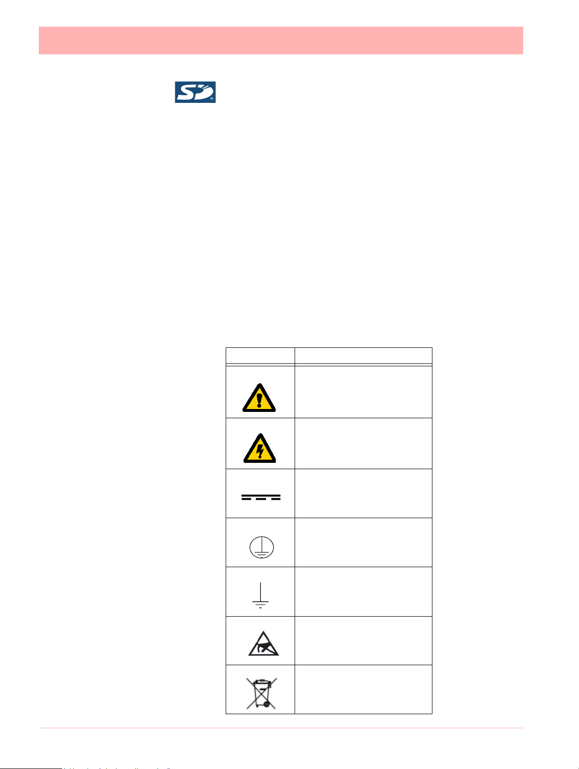
One or more of the following symbols may appear on the recorder labelling.
Table 1.2 : Safety Symbols
Symbol Meaning
Caution - refer to manual for
instructions
Caution - risk of electric
shock
Direct Current
Protective conductor terminal
Earth (ground) terminal
Static Electricity
Directive 2002/96/EC
WEEE: Waste Electrical and
Electronic Equipment
2 43-TV-25-41 Iss.4 GLO May 2015 UK
Page 11
Protocols used in this manual
WARNING
IMPROPER INTERRUPTION OF CONNECTIONS
Any interruption of the protective conductor outside the recorder, or disconnection of
the protective earth terminal is likely to make the recorder d angerous under some fault
conditions. Intentional interruption of the protective conductor is dangerous.
Failure to comply with these instructions could result in death or serious injury.
Static Electricity
All circuit boards and electronic modules associated with this recorder contain components
which are susceptible to damage caused by elec trostatic discharge. Should it be necessa ry
to handle such components, appropriate precautions in accordance with ANSI/ESD S20.20
Electrostatic Discharge Control Program Standard, should be observed.
Protocols used in this manual
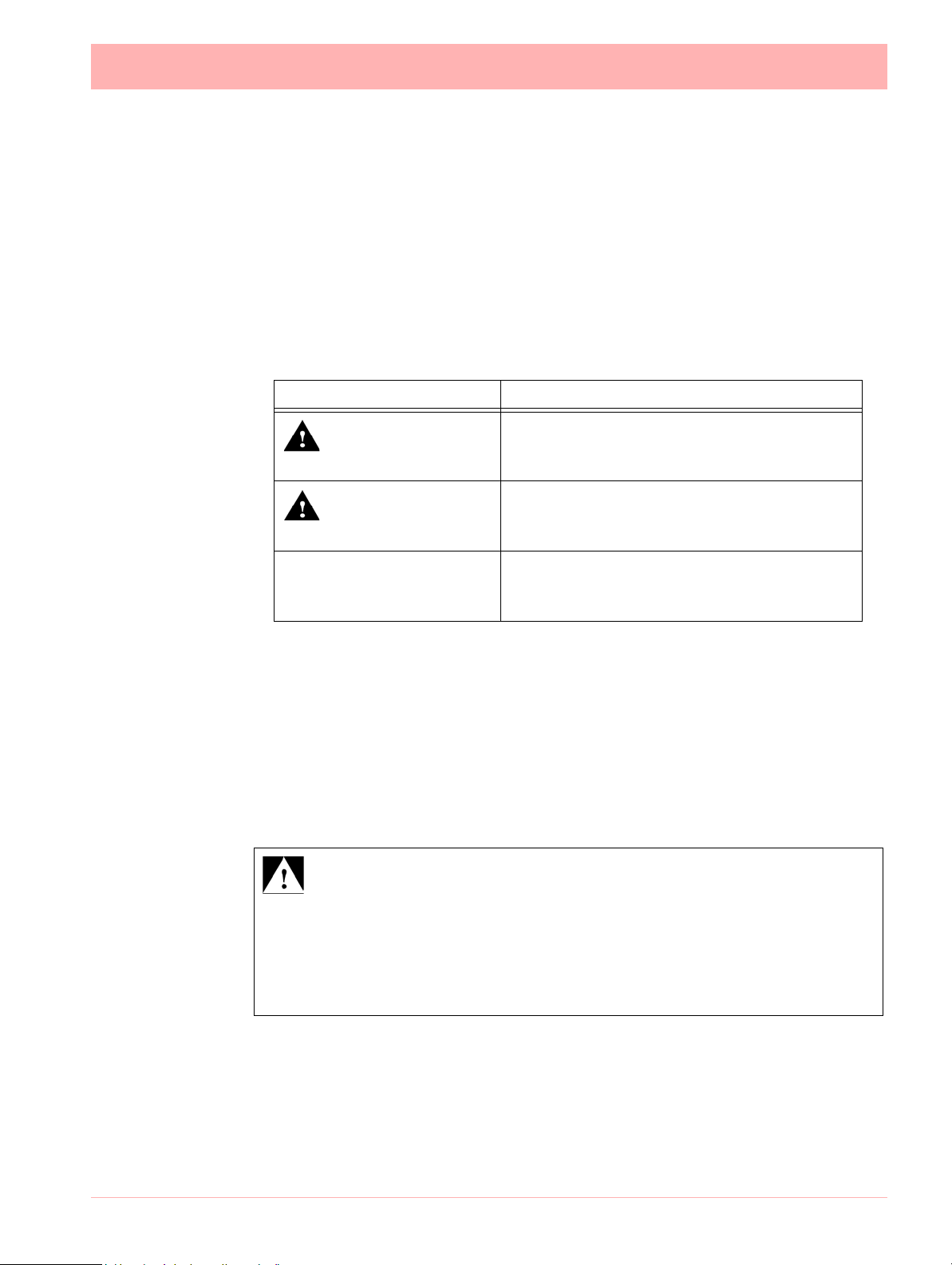
Safety and Symbol Identification
Symbol Description
Table 1.3 :
WARNING
CAUTION
NOTICE
Warnings and Safety Precautions
Do’s and Don’ts
1. DC inputs to the product should be provided by SELV power supply
2. The inputs of the product are supplied from SELV and should not exceed 50V.
3. Before any connections are made to the recorder, ensure the protective earth terminal
is connected to a protective conductor before applying power or any other connections.
The WARNING symbol indicates a potentially
hazardous situation, which, if not avoided, could
result in death or serious injury.
This CAUTION symbol may in dicates a potentially hazardous situation, which, if not avoided, may
result in property damage.
A NOTICE symbol indicates important information that must be remembered and aids in job
performance.
In order to comply with the requirements of safety standard EN 61010-1:2010, the
recorder should have one of the following as a disconnecting device, located within
easy reach of the operator, and be clearly labelled as the disconnecting safety device:
43-TV-25-41 Iss.4 GLO May 2015 UK 3
• A switch or circuit breaker which complies with the requirements of IEC 60947-1 and
IEC 60947-3.
Page 12
Warnings and Safety Precautions
WARNING
IMPROPER SIGNAL AND SUPPLY WIRING
Signal and supply wiring should be kept separate. Where this is impractical, shielded cables should
be used for the signal wiring. Where signal wiring is carrying, or could carry under fault conditions,
hazardous voltage (defined as >30 V rms and 42.4 V peak, or >60 Vd.c.), double insulation must
be used for all signal wiring.
Failure to comply with these instructions could result in death or serious injury.
WARNING
HAZARDOUS VOLTAGE LEVELS
Voltage levels above 30V rms and 42.4V peak or 60V dc are deemed to be
"Hazardous Live". Ensure operators are not exposed to hazardous voltage levels.
Failure to comply with these instructions could result in dea th or serious in jur y.
• A separable coupler which can be disconnected without the use of a tool.
• A separable plug, without a locking device, to mate with a socket outlet in
the building.
4. Whenever it is likely that protection has been impaired, the recorder should be made
inoperative and secured against operation. The manufacturer's service centre should
be contacted.
5. Repair is not to be attempted by a customer. Any adjustment or maintenance expected
of an operator as part of the normal operation of the product is referred to as Operational Maintenance. Any maintenance not expected of the operator is referred to as
Corrective Maintenance and is to be carried out only by authorized service personnel
or returned to an authorized repair centre.
6. Where conductive pollution such as condensation or conductive dust is present, adequate air conditioning, filtering and/or sealing must be installed.
7. This recorder contains one battery on the Processor board which must be treated and
disposed of with care. Batteries must not be short circuited. Batteries should be disposed of in accordance with local regulations, they must not be disposed of with normal
refuse.
Improper signal and supply wiring - WARNING
8.
9. If the equipment is used in a manner not specified by the manufacturer, the protection
provided by the equipment may be inadequate.
10. The protective earth terminal must remain connected (even if the recorder is isolated
from the mains supply) if any of the measuring, communications, or relay terminals are
connected to hazardous voltages.
Hazardous Voltage
Hazardous Voltages are defined by EN61010-1 as follows:
4 43-TV-25-41 Iss.4 GLO May 2015 UK
Page 13
Warnings and Safety Precautions
WARNING
EXPLOSION HAZARD
Do not remove or replace the Connectors, Fuse holders while circuit is live when
Flammable or Combustible atmosphere is present
WARNING
EXPLOSION HAZARD
Do not disconnect equipment when a flammable or combustible atmosphere is
present.
WARNING
EXPLOSION HAZARD
Do not open the enclosure or replace the battery when a flammable or combustibl e
atmosphere is present
WARNING
EXPLOSION HAZARD
Do not connect ro disconnect the equipment or memory card or USB device unless
the power has been swithced off or the area is known to be hazardou s
NOTICE
The Front door is tool secured and do not intende d to op e n du ring live cond itio n or
when flammable or combustible atmosphere is present. Ensure to lock the door for
use in hazardous location.
In case of GR Mini /Multi the front door is tool secured with cable tie whereas in DR
graphic recorder the front door is tool secured with Hex head Screw.
For use in hazardous locations
(only applicable to recorders with FM approval)
43-TV-25-41 Iss.4 GLO May 2015 UK 5
Page 14

Warnings and Safety Precautions
6 43-TV-25-41 Iss.4 GLO May 2015 UK
Page 15

Section 2: Installation
NOTICE
Should the original packing be destroyed or lost, new packaging can be ordered or as a
last alternative, then ONLY pack the recorder in polystyrene granules if the recorder is
FIRST sealed in a strong plastic bag. Failure to do this will invalidate your warranty.
Damage checks
Any damage caused to the recorder or the contents should be reported immediate ly to your
shipper.
Unpacking
Remove the contents, check the packaging and remove all d ocumentation and ac cessories
supplied. Retain the box and any packaging for future transportation.
Contents
Check that the contents and accessories are correct against the order or Model Selection
Guide using the model number on the recorder. Contact your authorised Honeywell dis-
tributor or Honeywell immediately should there be any query.
The contents are based on Unit Model Number ordered and will vary from unit to unit. The
following list is provided as a general guide and not specific to any single unit.
• Recorder - specification as ordered (check against the Model Selection Guide)
• Mounting fixings - Mounting clamps and panel gasket
• Connector kit - mating half connectors to recorder spec. Including a CJC connector for
Thermocouple operation.
• Quick Start Guide - to get you started
• First time Password system instructions - for ESS recorders only
• CD - Viewer software + documentation
• Plastic stylus x 2 (for use with the touch screen)
• Manual (optional) - Hard copy English, French or German
• Any other items ordered as an option (Model Selection Guide)
Re-packing
Environment and Location
• The recorder is designed to be mounted into a panel. See “Installation Instruc-
tions” on page 11.
• Mounting angle is unlimited. Choose a suitable location with an ideal viewing angle.
See “Mounting and Viewing Angles” on page 8.
• The location should be free from vibration.
• The environment should be of non-condensing humidity.
• The ambient temperature should be between 0C and 50C (32F to 122F).
• The relative humidity should be between 10% to 90%.
• In the presence of sustained strong EM Field (~10V/m or higher), deviation from the
accuracy specifications may occur. To improve performance under such installation
scenarios we recommend using twisted pair cables and/or ferrite cylinders (over
individual wires)
43-TV-25-41 Iss.4 GLO May 2015 UK 7
Page 16

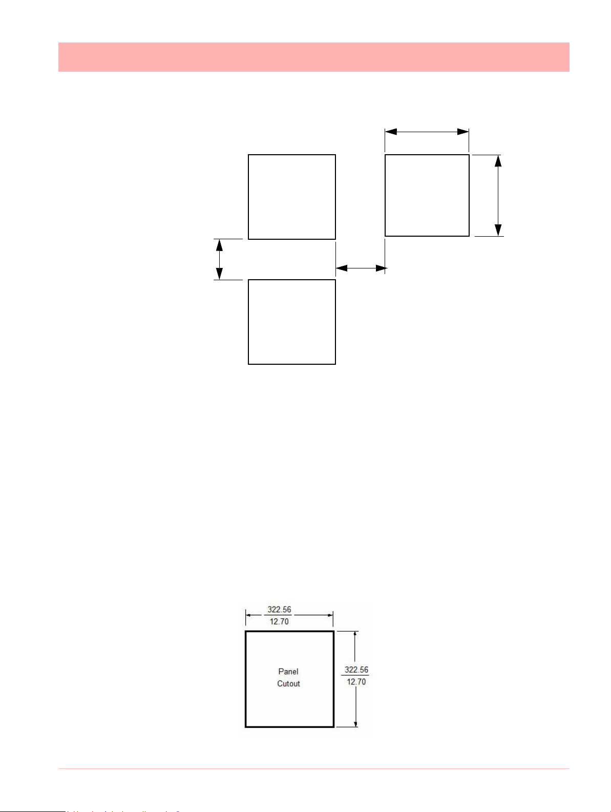
Mechanical Installation
Please note the recommended
spacing for adjacent mounting
Panel
Cut-out
Panel
Cut-out
Panel
Cut-out
138.00
(5.43”)
138.00
(5.43”)
>7.00
(0.28”)
>6.00
(0.237”)
+1
- 0
+1
- 0
Figure 2.1 Minitrend GR and eZtrend GR Panel cut-out
Mounting and Viewing Angles
Mounting - The Minitrend GR, Multitrend GR and eZtrend GR recorders have an unlimited mounting angle.
Mechanical Installation
Viewing - For the best view of the display the v
iewing angle should not exceed:
Minitrend GR 55from the left or right, 40looking down and 50 looking up at the recorder dis-
play.
Multitrend GR and DR Graphic70from the left or right, 45looking down and 55 look-
ing up at the recorder display.
eZtrend GR 45from the left or right, 10looking down and 30 looking up at the recorder display.
Panel cut-out size for the Minitrend GR and eZtrend GR recorders
8 43-TV-25-41 Iss.4 GLO May 2015 UK
Page 17
Mechanical Installation
Panel
Cut-out
Panel
Cut-out
Panel
Cut-out
281.00
(11.06”)
281.00
(11.06”)
>20.00
(0.787”)
>20.00
(0.787”)
Please note the recommended
spacing for adjacent mounting
Figure 2.2> Multitrend GR Panel cut-out
Figure 2.3>
DR Graphic recorder
Panel cut-out
Panel cut-out size for the Multitrend GR recorder
The Minitrend GR, Multitrend GR and eZtrend GR recorders are DIN Standard sizes
and should be panel mounted.
Panel cut-out size for the D R G r a p h i c recorder
Physical considerations
The recorder can be mounted flush in a panel or on the surface of a p anel or wa ll using th e
mounting kit supplied with the recorder. Adequate access space must be available at the
back of the panel for installation and servicing.
Overall dimensions
The overall dimensions and panel cutout requiremen ts for mounting the recorder are shown
in Figure 2.3
43-TV-25-41 Iss.4 GLO May 2015 UK 9
Page 18
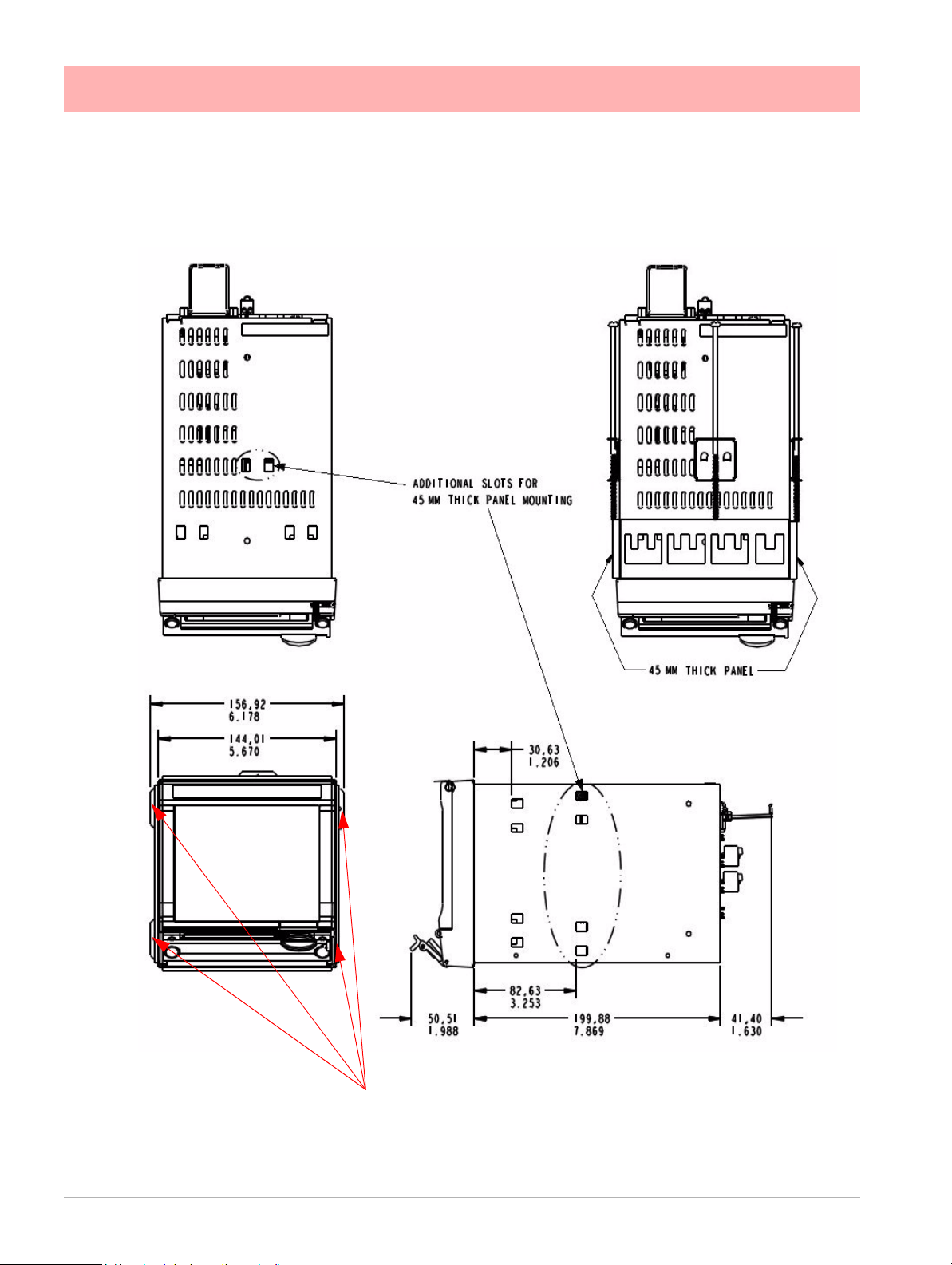
Mechanical Installation
4 Mounting clamp positions for 2 - 20mm panel thickness. For standard units fit
only two brackets on opposite sides of the unit, either top and bottom or left and
right slots. NEMA 4X rated recorders require all four mounting brackets to be fitted.
Figure 2.4> Miniitrend GR Recorder Dimensions and Mounting slots (including
45mm panel thickness)
Minitrend GR Dimension details
10 43-TV-25-41 Iss.4 GLO May 2015 UK
Page 19
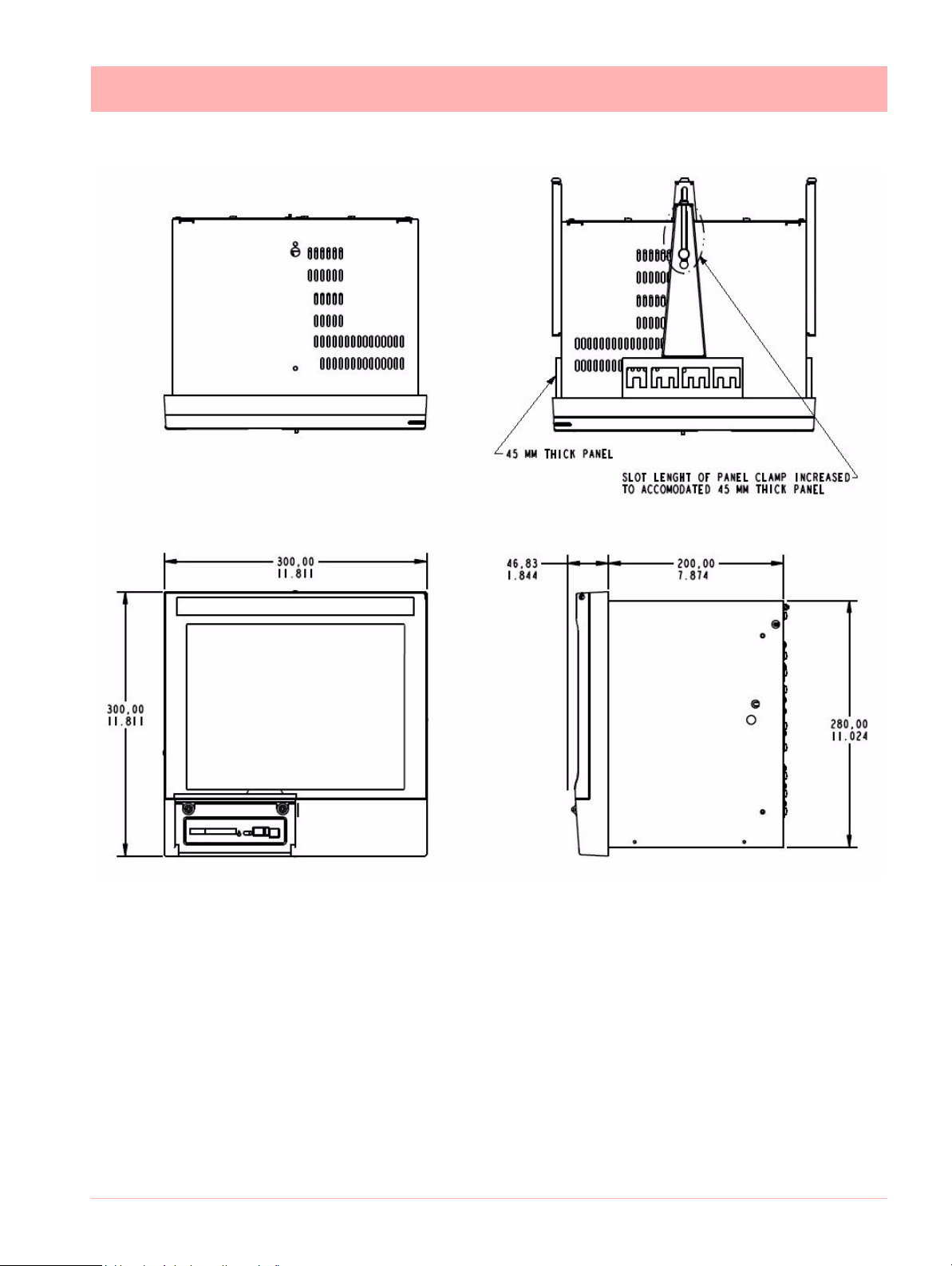
Mechanical Installation
Figure 2.5> Multiitrend GRRecorder Dimensions and Mounting slots
(including 45mm panel thickness)
Mu l t i t r e n d G R Dimension details
Installation Instructions
• Minimum panel thickness = 2mm (0.078”), max = 20mm (0.78”)
• Alternate panel mounting available thickness = 45mm (1.77”)
• Both recorders must be inserted from the front of the panel,
• Two mounting clamps are supplied and can be fixed either on the top and bottom
sides or on the left and right sides of the case.
43-TV-25-41 Iss.4 GLO May 2015 UK 11
Page 20
Mechanical Installation
4 Mounting clamp positions. For standard units fit only two
brackets on opposite sides of the unit, either top an d bo tt om
or left and right slots. NEMA 4X rated recorders require all four
mounting brackets to be fitted.
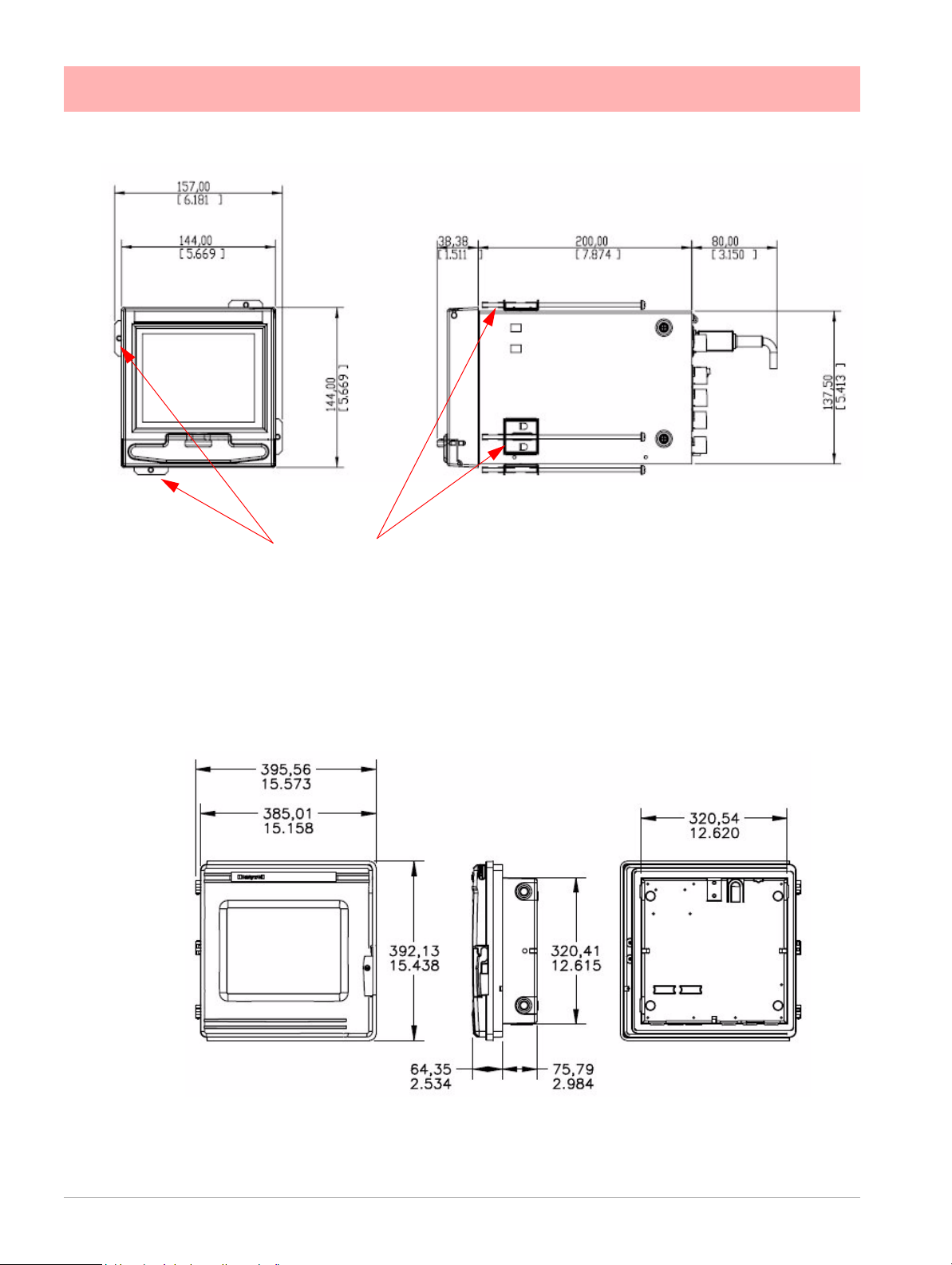
Figure 2.6 eZtrend GRrecorder dimensions
Figure 2.7 DR Graphic recorder dimensions
eZ t r e n d G R Dimension details
DR Graphic recorder Dimension details
12 43-TV-25-41 Iss.4 GLO May 2015 UK
Page 21

Mechanical Installation
CAUTION
CONTROL UNIT DAMAGE
Do not over tighten mounting clamp screws.
Minitrend GR
and eZtrend GR torque setting should be 0.5 - 0.75Nm/4.4 - 6.6lbf-in
Multitrend GR torque setting should be 0.5 - 0.70Nm/4.4 - 6.2lbf-in
Failure to comply with these instructions may result in product damage
Panel Mounting Clamp Installation
The Minitrend GR, Multitrend GR and the eZtrend recorders slide into the panel cut-
out and are held in place by two or four panel clamps (6 clamps for Minitrend GR recorder
with 45mm panel thickness). The panel clamps should be fitted on diagonally opposite sides
of the unit and tightened against the rear of the panel using two fixing screws.
The mounting clamp assembly and fitting instructions differ slightly for the two recorders.
Minitrend GR and eZtrend GR See Figure 2.6
1. Insert the panel gasket onto the recorder so it goes between the back of the
recorder bezel and the panel. From the front p anel, place u nit in the pa nel and
push through the panel.
2. To loosen each clamp, unscrew the long screw to accommodate the panel
thickness. Use either a Number 1 Phillips or Straight slot screw driver.
3. From behind the panel, the orientation of the clamp should be with the screw
head towards the rear of the unit.
4. Take the first clamp and locate the two lugs on the clamp into the slots on the
unit.
5. Take the second clamp and do the same but in the diagonal position to the
opposite side. Repeat for all other clamps.
6. Tighten the screw using a Number 1 Phillips or Straight slot screw driver and
the clamp will secure against the panel.
Multitrend GR See Figure 2.7
1. Insert the panel gasket onto the recorder so it goes between the back of the
recorder bezel and the panel. From the front p anel, place u nit in the pa nel and
push through the panel.
2. To loosen each clamp, unscrew the long screw to accommodate the panel
thickness. Use either a Number 1 Phillips or Straight slot screw driver.
3. From behind the panel, the orientation of the clamp should be with the screw
head towards the rear of the unit.
4. Position the circular mounting boss in the hole on one side of the case with the
lip of the boss inside the case. Ensure the front of the clamp is up against the
43-TV-25-41 Iss.4 GLO May 2015 UK 13
panel.
5. Fix the second clamp on the opposite side of the unit.
6. Tighten the screw using a Number 1 Phillips or Straight slot screw driver and
the clamp will secure against the panel.
Page 22

Mechanical Installation
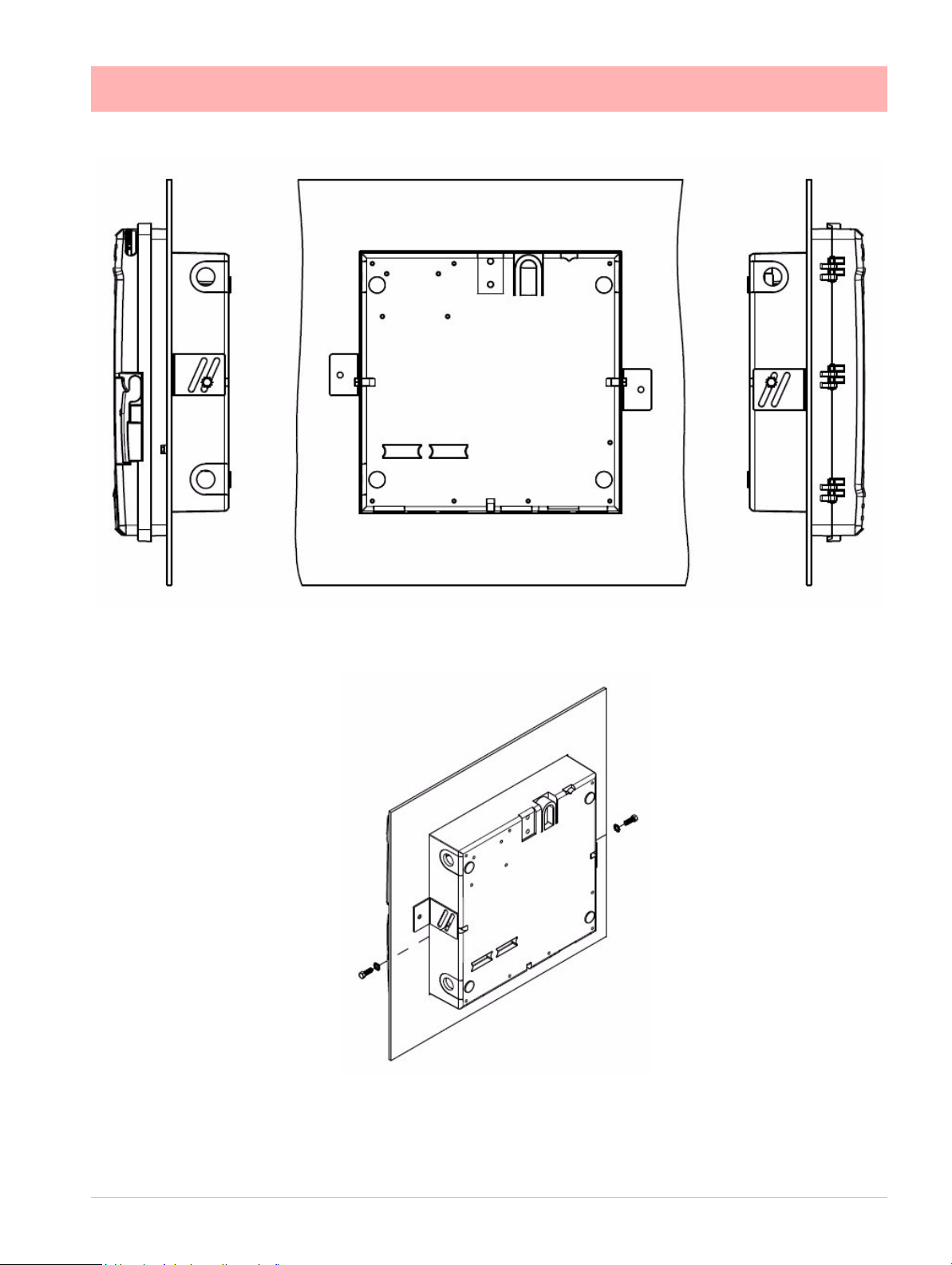
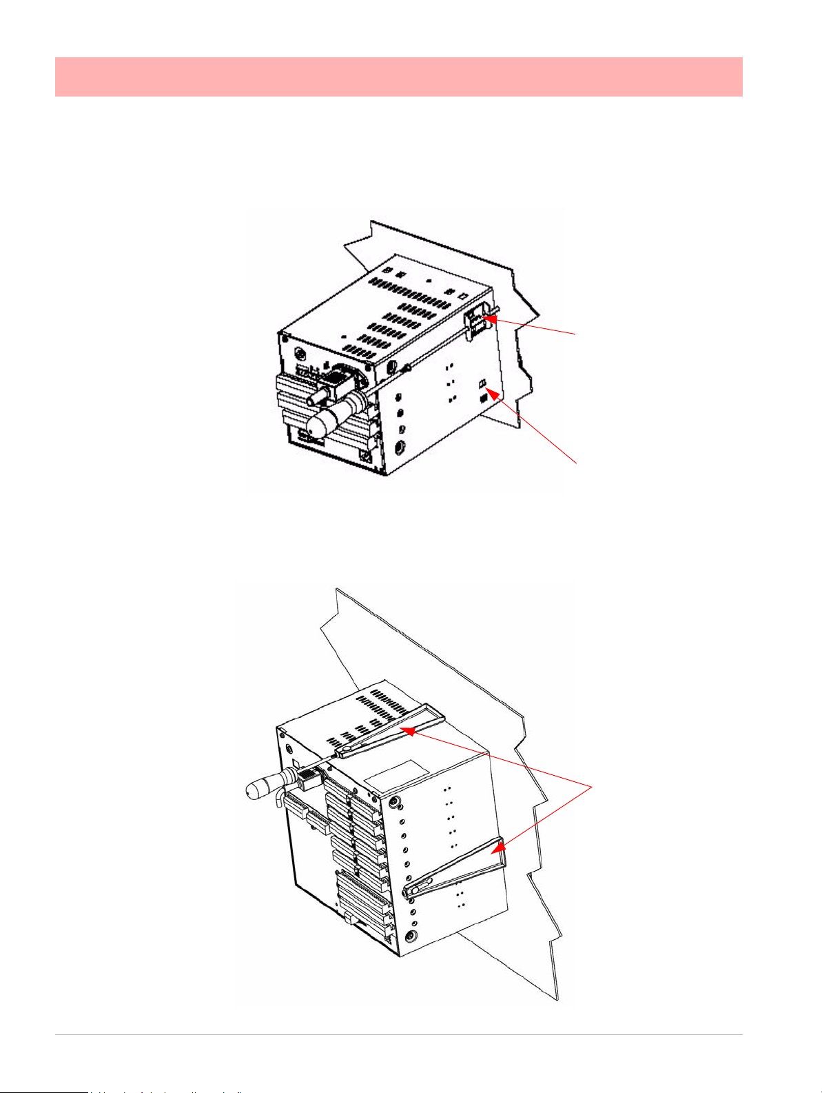
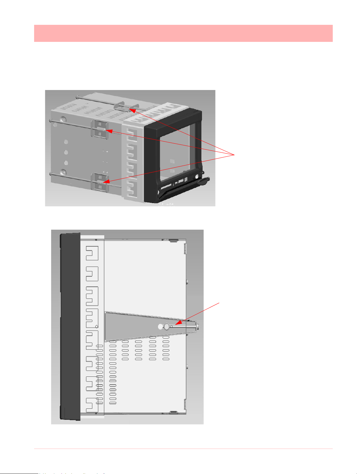
Figure 2.8 DR Graphic recorder dimensions
DR Graphic recorder See Figure 2.8
This section provides instructions for mounting the DR Graphic recorder using one of the
following methods:
• Flush in a panel
• Flush in a panel for recorders with NEMA 4
• On the surface of a wall for panel
Choose the method that meets your mounting requirements. use the associated dimension
drawings for reference.
How to remove knockouts for conduits
Before you mount the recorder, remove the appropriate plugs in the bottom and/or sides of
the recorder case for wire entry via 1/2" (12.7 mm) conduits. Refer to Figure 2.8 for plug
locations. To see recommended use of conduits for various types of wiring, refer to Figure
2.12 and Figure 2.13.
Mounting Flush in panel (new cut-out)
Procedure
1. At the appropriate location, make a square cutout in the panel. Cutout dimensions
should be 12.7 ±0.060 inches by 12.7 ±0.060 inches (322.56 ±1.52 by 322.56 ±1.52
millimeters).
2. Orient the recorder case properly and slide it into the cutout from the front of the panel.
Support the recorder as shown in Steps 3 and 4.
3. Refer to
side of the recorder case using a 1/4-20 x 1/2 inch hex screw for each bracket (mounting hardware supplied with recorder). Leave the screws slightly loose so you can adjust
the brackets.
4. While holding the recorder firmly against the panel, slide each bracket against the back
of the panel and tighten the screws.
14 43-TV-25-41 Iss.4 GLO May 2015 UK
See Figure 2.9.
Figure 2.9. From the back of the panel, attach a mounting bracket to each
Page 23
Mechanical Installation
Figure 2.9 Flush Mounting in a panel cutout
NOTE: Mounting brackets and attaching hardware are included in kit 30755065-501
43-TV-25-41 Iss.4 GLO May 2015 UK 15
Page 24
Mechanical Installation
2 mounting clamp
positions required on
two opposite sides of
the recorder. Nema 4X
requires all 4 clamps to
be fitted.
Mounting clamp slots
Figure 2.10 Minitrend GR Mounting Clamps
4 mounting clamp
positions (2 shown).
2 clamps are required on opposite
sides of the recorder
Figure 2.11 Multitrend GR Mounting Clamps
Mounting Clamp Diagram
16 43-TV-25-41 Iss.4 GLO May 2015 UK
Page 25
Mechanical Installation
Figure 2.12 Minitrend GR 45mm Mounting Clamps
6 mounting clamp positions
(3 shown) for mounting in 45mm
panel thickness. Mounting slots
shown in Figure 2.4 . Only 2
mountimg brackets need to be
fixed, in opposite positions.
Figure 2.13 Multitrend GR - 45mm
Mounting Clamps
4 mounting clamp positions (1 shown)
for mounting in 45mm panel thickness
on opposite sides of the unit. Mounting
slots shown in Figure 2.4 Both mounting clamps are required to be fitted
Mounting Clamp Diagram for 45mm panel thickness
43-TV-25-41 Iss.4 GLO May 2015 UK 17
Page 26

Mechanical Installation
Panel mounting recorder with NEMA4
Refer to Figure 2.14 and follow the procedure below to panel mount your re co rder if it ha s
a NEMA4.
1. Place the panel gasket onto the rear flange of the recorder case.
2. Install four #8-32 screws on each of the three mounting brackets so the ends of the
screw threads are flush with the face of the bracket.
NOTE: Screw heads to be flange side of brackets.
3. Insert the case with gasket into the panel opening.
4. Install one left hand and one right hand bracket with 1/4 x 3/8 long bolts and lockwashers on each side of the case.
NOTE: The notch on each bracket should be facing upward towards the top of the unit.
Do not tighten the hex bolts at this time.
5. Install the remaining right hand bracket on the top with the 1/4 x 3/4 long bolt and lockwasher. Do not tighten the bolt at this time.
6. Place a screwdriver blade on the notch of each bracket and firmly tap so that each
bracket firmly mates the case with gasket to the panel.
NOTE: Keep brackets parallel to case. Tighten the three 1/4 hex bolts to hold the brackets in place.
7. Start to tighten the #8-32 x 1/2 screws on the right side bracket. Alternate screws at
opposite ends until all four screws have a minimum of 10 lb-in of torque applied. Do the
same to both the left side and top brackets.
When completed all twelve screws should have a minimum of 10 lb-in of torque
applied. This assures the case and panel gasket are adequately sealed against the
panel.
18 43-TV-25-41 Iss.4 GLO May 2015 UK
Page 27
Mechanical Installation
Figure 2.14 Panel Mounting with NEMA4
43-TV-25-41 Iss.4 GLO May 2015 UK 19
Page 28

Mechanical Installation
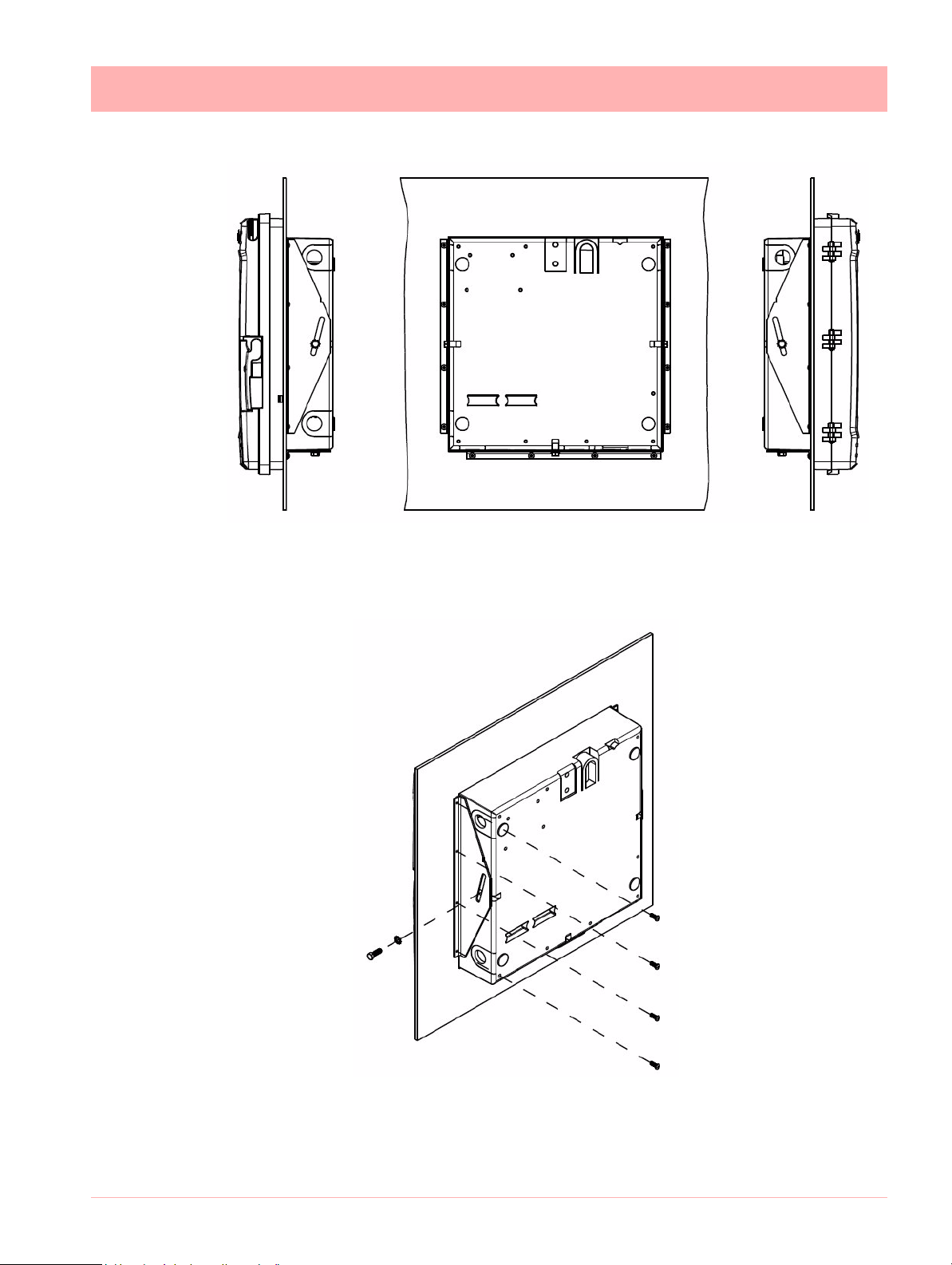
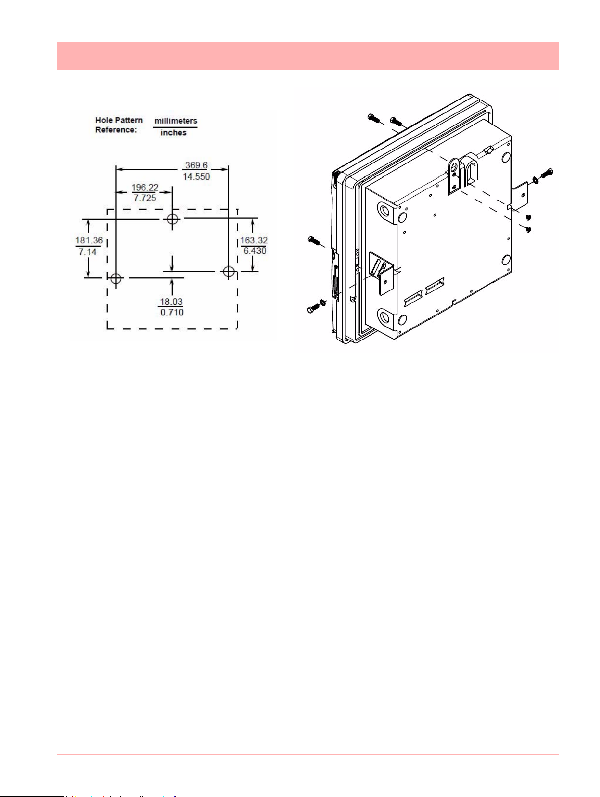
Mounting on Surface of panel or wall
Procedure
Refer to Figure 2-15 and follow the procedure below to mount your recorder on a surface
(panel or wall).
NOTE: Three (3) screws must be supplied by the user for attaching the mounting hardware
(brackets and support hook) to panel or wall.
Using two flat-head 10-32 x 1/4-inch screws supplied with the recorder, fasten the su pport
hook into the recess at the back of the recorder case as shown in Figure 2-15.
1. Using 1/4-20 x 1/2-inch hex screws and lockwashers, attach a mounting bracket to
each side of the case. Leave the screws slightly loose so as to permit some adjustments of the brackets.
2. On the panel, mark the locations for the three holes, as shown by the hole pattern in
Figure 2-15.
3. Using a drill of appropriate size for user-supplied screws, drill a hole in the front of the
panel for the eye of the support hook.
4. Insert the screws for the support hook into the panel, allowing the screw head to protrude approximately 5/16-inch.
5. Hang the recorder support hook on the screw. Make sure that the locations for the other
two holes (marked in Step 3) are correct. If not, make sure that the recorder is aligned
vertically, and use the brackets as templates to mark the proper locations.
6. Remove the recorder from the panel and drill the other two holes.
7. Hang the recorder on the screw by the support hook and insert the other two user-supplied screws through the brackets into the panel. Tighten the two hex screws that
attach the brackets to the case.
20 43-TV-25-41 Iss.4 GLO May 2015 UK
Page 29
Mechanical Installation
Figure 2.15 Surface Mount on wall or panel
43-TV-25-41 Iss.4 GLO May 2015 UK 21
Page 30

Electrical Installation
WARNING
ENSURE SAFETY EARTH CONNECTION
Always ensure the unit is connected to safety earth when connecting to an AC or DC
supply.
Failure to comply with these instructions could result in death or serious injury.
Installation Category
• Installation category - Installation category II, Pollution degree 2
• Follow National and local electrical codes for installation in a Class 1, Div.2 area.
For voltage, frequency and power refer to the appropriate Specification sheet: See “Sec-
tion 12: Technical Data & Specifications” on page 303.
Fuses
There is a fuse situated on the DC input version power supply, type 2A time-delay, this can
be replaced by the user. Replacement of fuse s sho u ld be car rie d ou t by qualified service
personnel.
If the fuse should blow again there is probably a problem elsewhere within the unit and the
recorder should be returned for inspection to your authorised Honeywell distributor or
Honeywell Service department.
Cables
Electrical Installation
To fully comply with the requirements of the CE Mark, all cables connected to the rear of
the unit should use screened cable terminated at both ends. A low impedance earth cable
(<50 m) must be connected to the earthing stud on the rear of the recorder, to ensure
that the recorder is always earthed.
Before performing any installation please read the section on “Safety” on page 2.and
“Warnings and Safety Precautions” on page 3.
All connections to the unit are made via the rear panel, the layout of which is shown in
page 24
Note: The eZtrend GR
to the recorder case using a low impedance bond. Also avoid use of a length of wire between
the cable screen and the recorder case.
Analogue Input card (Slot A). Cable screen must be well conne c te d
Signal Wiring
Your recorder is intended fo r panel- mou nt use, and on ly the fron t face is inte nded to be
exposed to the operator. Disconnection from the supply MUST be made possible by
means of a switch, circuit breaker or other means of supply isolation.
The disconnection device must be included in the panel installation, clearly marked, in
close proximity to the recorder, and within easy reach of the operator. The protective earth
22 43-TV-25-41 Iss.4 GLO May 2015 UK
terminal must remain connected (even if the recorder is isolated from the mains supply) if
any of the analogue or relay terminals are connected to hazardous voltage.
Page 31

AC Power
CAUTION
UNIT DAMAGE CONTROL
To protect against component failures the user should fit an external fuse for the DC
input power supply. The value should be 4A, time delay, high breaking capacity, minimum 60Vdc.rated.
Failure to comply with these instructions may result in product damage
WARNING
HAZARDOUS VOLTAGES
When using the recorder as portable equipment the optional rear cover must be fitted
when hazardous voltages are connected.
Failure to comply with these instructions could result in death or serious injury.
Electrical Installation
AC supply is connected via the standard configuration IEC chassis plug on the power supply, 100 - 240 Vac, 50-60 Hz (40W Minitrend GR, eZtrend GR and 50VA DR Graphic
and 60W Multitrend GR). Absolute limits 90V-132Vac (110V) and 180V-264Vac (240V).
AC/DC Power Suppy
For the Minitrend GR the supply range is 12-30V DC (absolute limits are 12V to 30V DC).
The DR Graphic and Multitrend GR the supply range is 24V DC +/- 10% (absolute limits
are 20V to 55V DC), the AC range is 20 to 30V AC. The Minitrend GR and the eZtrend
GR also has an 18V option with supply range 12VDC -30VDC / 12VAC -20VAC.
DC power rating are as follws Minitrend GR and eZtrend GR: 40W, Multitrend GR:
60W, DR Graphic: 40W.
Power to the D.C.variant is connected via a rectangular 3-way connector as identified in
page 24 for the Minitrend GR and page 24 for the Multitrend GR and page 26 for
the DR Graphic.
Note: Inrush Current = 75A max(High Line, Cold Start) for all recorders.
43-TV-25-41 Iss.4 GLO May 2015 UK 23
Page 32

Electrical Installation
Figure 2.10 Minitr end GR Rear panel
SPNC Relay
Earth screw (ground)
24V TX Power
Supply Output
AC supply
100 - 250 VAC
Analogue Input /
Analogue Output
/ or Pulse Input
Slot A
Slot B
Alarm Relay or
Digital I/O
Slot G
CJC Sensor
24V DC/AC Input
USB Host
Ethernet
Wire seal provision
RS485
Earth screw
(ground)
24V DC/AC Input
SPNC
Relay
24V TX
Power Supply
Output LED
AC supply
100 - 240 VAC
Analogue Input/
Analogue Output/
or Pulse Input
Slot A
Slot B
Slot C
Slot D
Slot E
Slot F
Alarm Relay
or
Digital I/O
Slot G
Slot H
Slot I
Ethernet
USB Host
Figure 2.11 Multitrend GR Rear panel
CJC Sensor
position in the
middle of the
Analogue Input
connector.
Slots A - F
RS485
Wire Seal
24 43-TV-25-41 Iss.4 GLO May 2015 UK
Page 33

Electrical Installation
Card and Slot positions
Table 2.1 : Card priority positions
Cards
Analogue Input card A, B A, B, C, D, E, F A*, B (option) A, B
Analogue Output card B E, F - B
Pulse Input card A, B A, B, C, D, E, F - A, B
Alarm Relay or Digital I/O
card
Minitrend GRMultitrend
GR
G G, H, I G B
eZtrend
GR
DR Graphic
43-TV-25-41 Iss.4 GLO May 2015 UK 25
Page 34

Electrical Installation
Figure 2.12 DR Graphic slot positions and connections
DR Graphic card positions
26 43-TV-25-41 Iss.4 GLO May 2015 UK
Page 35

Electrical Installation
Figure 2.13 DR Graphic Electrical connections
DR Graphic cards; selection jumper table
Table 2.2 :
AI/AO/Pulse J8 & J9: Link 1 & 2
Slot B
Alarm/DI/DO J8 & J9: Link 2 & 3
NOTE: Do not disturb J4 & J5 jumpers in positions 1 & 2 for Slot A. These are for future
provision.
43-TV-25-41 Iss.4 GLO May 2015 UK 27
Page 36

Electrical Installation
Earth screw
(ground)
12 to 30VDC / 12
to 20VAC Input
Instrument power
(option)
24V TX Power
Supply Output
AC supply
100 - 240 VAC
Analogue Input
card (option)
Slot B
Alarm Relay or
Digital I/O
Slot G (option)
Wire seal provision
CJC Sensor
(not shown)
Analogue Input /
Ethernet connection
card (std) - Slot A
ETHERNET
Figure 2.14 eZtren d GR Rear panel
SPNC Relay
28 43-TV-25-41 Iss.4 GLO May 2015 UK
Page 37

Electrical Installation
WARNING
HAZARDOUS VOLTAGES
Insulation from channel to channel: Normally a cha nnel can b e safe ly conn ected to a
hazardous voltage up to 300V AC common mode* with respect to earth. However,
where a channel is connected to a safety low voltage circuit, an immediately adjacent
channel must be adequately insulated from hazardous voltages between 150V AC
and 300V AC max. This insulation should comprise of at least 1.5mm air gap, or a barrier rated greater than 1400V AC. This is to ensure that protection of the safety low
voltage circuit is fully maintained.
*Common Mode voltage is a voltage applied between the whole channel and earth,
not between pins on a channel. 300V AC is permitted at Measurement Category CAT
ll (Overvoltage Category ll)
Failure to comply with these instructions could result in death or serious injury .
NOTICE
For 12 and 24-way connectors; torque setting 0.4 Nm/3.5lbf-in. Do not over tighten.
Recommended wire size for termination connector is 22-12 AWG (American Wire
gauge) equivalent to 22-14 SWG (Standard Wire Gauge). AWG metric 0.6426-
2.052mm in diameter or SWG metric 0.71 - 2.03mm in diameter.
Analogue Input Card
Each Analogue Input card has up to 8 input channels for the Minitrend GR and the Multitrend GR and up to 6 channels for the eZtrend GR. Connections are made via 2 x 12-
way screw terminal plugs that fit into a PCB header on the rear of the unit. The 2-way CJC
sensor should remain fitted in the central 2-way header.
The Minitrend GR
(2 x 8 channel cards). The slot positions are A & B, these are identified on the rear panel on
the back of the unit. Either slot can be used, it is recommended that slot A is used if only one
card is fitted.
The Multitrend GR can have up to 6 analogu e input cards fitted, up to 48 input channels.
The slot positions A, B, C, D, E or F; these are identified on the rear panel. PC boards are
fitted in order, slot ”A” starts from the top.
can have two analogue input cards fitted giving up to 16 input channels
The eZtrend GR
providing up to 6 more channels. This card would be used after using the 3 or 6 channel
standard eZtrend GR
alogue Input (Standar d) card” on p age 32.The DR Graphic Recorders can have two
analogue input cards fitted giving up to 16 input channels (2 x 8 channel cards). The slot
positions are A & B, these are identified on the IO card chassis inside the unit. Either slot
can be used, it is recommended that slot A is used if only one card is fitted.
Ensure to connect the jumpers on DR Graphic backplane card as per DR Graphic Cards
Selection Jumper Table on page 27 before installing the AI cards. See “eZtrend GR An-
alogue Input (Standard) card” on page 32.
To fit this option card into the eZtrend GR recorder you will require an expansion card to
interface to the recorder.
can use this card as an additional Analogue Input card fitted in Slot B,
Analogue Input card which is fitted in Slot A, see “eZtrend GR An-
43-TV-25-41 Iss.4 GLO May 2015 UK 29
Page 38
Electrical Installation
CAUTION
CONTROL UNIT DAMAGE
Do not apply a hazardous live voltage between + and - pins within a channel. ( eg. 60V
maximum on voltage ranges, 5V maximum on millivolts ranges). Do not apply a voltage
above 1.2V to the * pin.
Failure to comply with these instructions may result in product damage
Rear Covers
Optional rear covers are available for these products (except for the DR Graphic recoder
which does not require a rear cover) and it is recommended to use the rear cover to
protect the wiring and to minimize external effects that could impact the performance of the
CJC. For the rear cover part number, see “Section 10: Spares List” on page 281.
Analogue Input Channel Numbers
Analogue Input cards are either 4, 6 or 8 channels with a full length connector taking up 8
channels even if only 4 or 6 are operational.
Table 2.3 :
Minitrend GR Multitrend GR and DR Graphic Analogue Input card
Card Position
Channel number 1 to 8 9 to 16 17 to 24 25 to 32 33 to 40 41 to 48
Slot A Slot B Slot C Slot D Slot E Slot F
Table 2.4 :
Card 3 CH. 6 CH. 9 CH. 12 CH.
A 1-3 1-6 1-3 1-6
B 9-14 9-14
eZtrend GR Analogue Input cards
Analogue Input Connection Details
Current Input
For Current (mA) Input fit a 10
analogue connector. Figure 2.15 shows a 10
current (mA) input.
Ensure polarity of thermocouple is correct.
Thermocouples
resistor across the + and - pins of the 12-way mating half
(±0.1%) resistor fitted to channel 5 for a
Resistance Thermometers
If using 2 wire R/T the + and - terminals must be linked together. See “Figure 2.16 Input
signal wiring” on page 31..
Analogue Input Signal Wiring
30 43-TV-25-41 Iss.4 GLO May 2015 UK
Page 39

Electrical Installation
CH1 CH2 CH3 CH4 CH5 CH6 CH7 CH8
CJC
Figure 2.15 Analogue Input connector
-ve
+ve
Current
10R
Ohms
R/T
R/T
2-wire R/T
3-wire R/T
-ve +ve
Figure 2.16 Input signal wiring
Passive Burnout
Thermocouples
Volts/mV
-ve +ve
-ve
+ve
Active Burnout
Thermocouples
R/T
4-wire R/T
This Analogue Input card can be used as an option to add up to 6 more Analogue Input
channels for the eZtrend GR
numbers 9 to 14. The standard fit Analogue Input card is fitted in slot A with up to 6 channels
(channels numbers 1 to 6).
To fit this option card into the eZtrend GR recorder you will require an expansion card to
interface to the recorder.
recorder. This will fit into Slot B and will display as channel
43-TV-25-41 Iss.4 GLO May 2015 UK 31
Recorder setup will be required if wiring changes are made for Active Burnout Thermocouples. See “*Thermocouple Wiring Changes.” on page 76.
Page 40

Electrical Installation
1 2 3 4 5 6 7 8 9 10 11 12
13 14 15 16 17 18
- +
*
- +
*
- +
*
- +
*
- +
*
- +
*
CH.1 CH.2 CH.3 CH.4 CH.5 CH.6
Figure 2.17 eZtrend GR Analogue Input card (std) - Slot A
Thermocouple Active Burnout status can be viewed in the Main Menu > Status >Diagnostics
> Analogue Input screen, Input column. The Health Watch/Maintenance firmware option
must be active to access the Maintenance and Diagnostic buttons. See “Diagnostics” on
page 200.
For the eZtrend GR
link between positive (+) and negative (-).
recorder Active Burnout is not available. Ohms measurements must have the
CJC Connectors
The CJC connector resides between channel 4 and channel 5 on the Analogue Input card.
For information on connecting the CJC sensor, see “Figure 2.15 Analogue Input connec-
tor” on page 31.
For the
eZtrend GR recorder this is available on the Analogue Input card (option).
e Ztrend GR Analogue Input (Standard) card
The eZtrend GR is fitted with a standar d Ana logue Inpu t card in Slot A, with up to 6 channels. The card is also fitted with an Ethernet port as standard. Connection is made via 1 x
18-way screw terminal plugs that fit into a PCB header on the rear of the unit. To fit up to a
further 6 analogue input channels, see “Analogue Input Card” on page 29
32 43-TV-25-41 Iss.4 GLO May 2015 UK
Page 41

Electrical Installation
WARNING
HAZARDOUS VOLTAGES
Insulation from channel to channel: Normally a channel can be safely connected to a
hazardous voltage up to 150V AC common mode* with respect to earth. However,
where a channel is connected to a safety low voltage circuit (i.e. is accessible for operators to touch), any channel within the same 'input bank' must be limited at all time s
to a maximum of 55Vac or 140Vdc**. This is to ensure that protection of the safety low
voltage circuit is fully maintained.
The inputs are divided into two banks: inputs 1 to 3 are one bank, and inputs 4 to 6 (if
fitted) are another bank. A voltage of up to 150V AC common mode can be applied on
one bank as long as any safety low voltage circuits are on the other bank. The recorder
is protected against accidental connection of a voltage up to 240V AC common mo de
which might occur as a temporary fault condition, provided there are no safety low voltage circuits connected to the same input bank as the channel with the fault.
*Common Mode voltage is a voltage applied between the whole channel and earth,
not between pins on a channel.
** this reduces to 33Vrms or 70Vdc if any channel within the input bank is configured
as an ohms or R/T measurement.
Failure to comply with these instructions could result in death or serious injury .
CAUTION
CONTROL UNIT DAMAGE
Do not apply a hazardous live voltage between + and - pins within a channel (e.g . 60V
maximum on voltage ranges, 5V maximum on millivolts ranges).
The * pin should be connected only as part of ohms or R/T me asurements. Ohm s and
R/T measurements share a common connection (* pin) with all channels in the same
bank (the inputs are divided into two banks: inputs 1 to 3 are one bank, and inputs 4 to
6, if fitted, are another bank). To avoid damage, ensure t hat a channel selected as ohms
or R/T remains floating, i.e. the sensor is not connected to any external voltage.
Alternatively, if an ohms or R/T sensor must be biased to an external voltage, ensure
that the other two channels within the same input bank a re floating or are biased to the
same voltage (i.e. - inputs of all three channels connected to the same voltage).
Failure to comply with these instructions may result in product damage
43-TV-25-41 Iss.4 GLO May 2015 UK 33
Analogue Output Card
Not available on the eZtrend GR recorder.
The Analogue Output card connections are made via 1 x 12- way screw termi nal plu g that
fits into a PCB header on the rear of the unit.
The Analogue Output card position for the Minitrend GR, Multitrend GR and DR
Graphic shown in Table 2.1 on page 25.
Page 42

Electrical Installation
WARNING
HAZARDOUS VOLTAGES
Insulation from channel to channel: Normally a channel can be safely connected to a
hazardous voltage up to 300V AC common mode* with respect to earth. However,
where a channel is connected to a safety low voltage circuit, an immediately adjacent
channel must be adequately insulated from hazardous voltages betwe en 150V AC and
300V AC max. This insulation should comprise of at least 1.5mm air gap, or a barrier
rated greater than 1400V AC. This is to ensure that protectio n of the safety low voltage
circuit is fully maintained.
*Common Mode voltage is a voltage applied between the whole channel and earth, not
between pins on a channel. 300V AC is permitted at Measurement Category CAT ll
(Overvoltage Category ll)
Failure to comply with these instructions could result in death or serious injury.
34 43-TV-25-41 Iss.4 GLO May 2015 UK
Page 43
Electrical Installation
Output 1 Output 2 Output 3
Output 4
Loop -
Loop +NCLoop -
Loop +
NC
Loop -
Loop +NCLoop -
Loop +
NC
1 2 3 4 5 6 7 8 9 10 11 12
NC = Not
connected
Analogue Output Channel Numbers
The Analogue Output cards are either 2 or 4 channels using a connector that only ta kes up
half the length of the connector slot. Looki ng from the rear o f the unit the An alogue Out connector is on the left of the Analogue slot with a blanking plate on the right.
Table 2.5 :
Analogue Output card
Card Position
Channel number 9 to 12 33 to 36 41 to 44
Slot B Slot E Slot F
Analogue Output Connection Details
Pulse Input Card
The Pulse Input card connections are made via 1 x 12-way screw terminal plugs that fits
into a PCB header on the rear of the unit.
The Pulse Input card position for the Minitrend GR
Graphic are shown in Table 2.1 on page 25
The Pulse Input card is not available on the eZtrend GR
option card has 4 channels that can be set as pulse inputs (channels 1 to 4). T he operating
frequency for pulse inputs on the Digital I/O card is 1kHz max.
Input: Low < 1V, High >4V to <50V DC (8V to 50V p-p AC) or Volt free input: Low = short
circuit, High = open circuit.
43-TV-25-41 Iss.4 GLO May 2015 UK 35
and for the Multitrend GR and DR
recorder, however, the 8 Digital I/O
Page 44

Electrical Installation
WARNING
HAZARDOUS VOLTAGES
Insulation from channel to channel: Normally a channel can be safely conne cted to a
hazardous voltage up to 300V AC common mode* with respect to earth. However,
where a channel is connected to a safety low voltage circuit, an immediately adjacent
channel must be adequately insulated from hazardous voltages between 150V AC
and 300V AC max. This insulation should comprise of at least 1.5mm air gap, or a barrier rated greater than 1400V AC. This is to ensure that protection of the safety low
voltage circuit is fully maintained.
*Common Mode” voltage is a voltage applied between the whole channel and earth,
not between pins on a channel. 300V AC is permitted at Measurement Category CAT
ll (Overvoltage Category ll)
Failure to comply with these instructions could result in death or serious injury.
- + NC - + NC - + NC - + NC
Channel 1 Channel 2 Channel 3 Channel 4
Pulse Input Channel Numbers
The Pulse Input card has channels using a connector that only takes up half the length of
the connector slot. Looking from the rear of the unit the Pulse Inp ut connector is on the right
of the slot with a blanking plate on the left.
Table 2.6 :
Pulse Input card
Card Position
Channel number 1 to 4 9 to 12 17 to 20 25 to 28 33 to 36 41 to 44
Slot A Slot B Slot C Slot D Slot E Slot F
Pulse Input Connection Details
Do not connect anything to terminals marked NC (Not Connected). For Frequency and Voltage levels see “Specification Tables” on page 307.
36 43-TV-25-41 Iss.4 GLO May 2015 UK
Page 45

Electrical Installation
Minitrend 24V DC TXP
24V 0V
Figure 2.16 Transmitter Power Supply card for the Multitrend GR recorder
24V
0V
LED
Transmitter Power Supply Card
The Minitrend GRand the eZtrend GR Transmitter
power supply
power supply card within the unit. Connection is made via
a 2-way connector at the rear of the unit, the mating half
is supplied with this option. For connector position see
page 24. The 24V transmitter power supply is not isolat-
ed from the recorder, and is not referenced to ground.
The Multitrend GR
the power supply card within the unit. Connection is made via two 10-way connectors, see
page 24, mating halves supplied with this option. The Multitrend GR transmitter power
supply is isolated from the recorder.
A red LED light will illuminate when there is voltage on the connectors. The LED is situated
between the two connectors at the back of the unit. See page 24.
Recommended wire size for termination connector 22-12 AWG (22-14 SWG).
option is 24V DC 200 mA and is fitted to the
Transmitter power supply option is 24V DC 1 A and is fitted below
43-TV-25-41 Iss.4 GLO May 2015 UK 37
Page 46

Electrical Installation
WARNING
HAZARDOUS VOLTAGES
Digital Input/Output card channels must not be connected to any hazardous live voltages (no higher than 30V AC rms or 60V DC).
Alarm Relay Card channels
Alarm Relay Card channels can be connected to hazardous voltages up to 300V AC,
at Measurement Category CAT II (Overvoltage Category II)
Failure to comply with these instructions could result in death or serious injury.
NOTICE
For 12 and 16-way connectors; torque settin g 0. 4 Nm /3 .5lb - in. Do not over tigh te n.
Recommended wire size for termination connector is 22-12 AWG (22-14 SWG)
Alarm Relay Cards & Digital Input/Output Cards
The Alarm Relay Cards and the Digital Input/Output Cards are both options avai lable for
the Minitrend GR, Multitrend GR, eZtrend GR and the DR Graphic recorders.
To fit these option cards into the eZtrend GR recorder it requires an expansion card to interface to the recorder.
All Alarm Relay card outputs provide 240V AC isolation channel to chann el and channe l to
recorder. Digital Input/Outputs will provide isolation to 100V AC test voltage (not for mains
connection).
All digital inputs have volt free contacts, and are sampled at 10Hz max.
The Minitrend GR, eZtrend GR and the DR Graphic recorders have only one slot avail-
able for digital inputs and relay outputs for eith er a 4 or 8 channel Alarm Relay card or an 8
or 16 channel Digital I/O card fitted in slot G, the position is identified on the rear panel. The
16 channel Digital I/O card is not available on the eZtrend GR recorders.
The Multitrend GR can have up to three Alarm Relay cards fitted in any combination of
Alarm Relay card or Digital I/O cards. The first Alarm Relay card or Digital I/O card is fitted
in slot G, any additional cards will locate in positions H and I.
4 and 8 Alarm Relay Cards
The 24-way connector for the Alarm Relay Card, connects to 3 A, 240 VAC SPCO relays.
The pin-outs for 4 and 8 relay Alarm Relay cards are numbered from left to right and they
read as follows for each channel; NC (normally closed), C (c ommon) , NO ( nor mally ope n) .
Devices driven by the relays are connected via two 12-way screw terminal plugs.
The last two channels, 7&8, 23&24 or 39&40, can be used as digital inputs, conn ect across
Common (C) and Normally Open (NO).
38 43-TV-25-41 Iss.4 GLO May 2015 UK
Page 47

Electrical Installation
CAUTION
IMPROPER MAINS SWITCHING
For 8 channel Alarm Relay cards.
Switching mains on the normally-open contact on channe ls 7 and 8 is not recommended,
as surges and spikes on the mains supply could cause damage to the input circuitry.
The normally-closed contact is unaffected, and can be used like all the other channels.
A Form C dry contact relay is used for this type of card. The inputs are designed to accept
“Dry contact, no volt inputs”. The relays should be used for non-inductive loads only where
a device requires a voltage to operate it, such as a 12 Volt buzzer, connect it to the normally
open (NO) contacts (unless the fail-safe setting is activated).
The maximum voltage which may be used with the alarm relays is 240V
Alarm Relay Channel Numbers
The Alarm Relay cards are either 4 or 8 channels with a full length connector taking up 8
channels even though the cards only operate on 4 channe ls or 8 channe ls. The 8 channels
Alarm Relay card has 2 digital inputs available on the last 2 channels. There are no Digital
Inputs available on the 4 channels Alarm Relay card.
Table 2.7 :
Alarm Relay card 4 channel Alarm Relay card 8 channel
Card
position
Slot G 1 to 4 N/A Slot G 1 to 8 7 & 8
Slot H 17 to 20 N/A Slot H 17 to 24 23 & 24
Slot I 33 to 36 N/A Slot I 33 to 40 39 & 40
Channel
number
Digital
Inputs
Card
position
Channel
number
Digital
Inputs
DR Graphic recorders alarm card slot position and channel number mapping
Table 2.8 :
Alarm Relay card 8
Card position Channel number Digital Input s
Slot B 1 to 8 7 & 8
43-TV-25-41 Iss.4 GLO May 2015 UK 39
Page 48

Electrical Installation
Figure 2.17 Alarm Relay Card connector details
NC C NO NC C NO NC C NO NC C NO NC C NO NC C NO NC C NO NC C NO
Relay contacts position
Channels 7 and 8 can
be set as Digital Inputs.
(Use C and NO)
CH 1 CH 2 CH 3 CH 4 CH 5 CH 6 CH 7 CH 8
NC = Normally Closed
C = Common
NO = Normally Open
NOTICE
For Digital Inputs, short together the 2 pins of the channels with a switch or a relay.
8 and 16 Digital Input/Output Card
The 16 channel Digital I/O card is not available on the eZtrend GR recorders.
Digital Input/Output Card has 1A 24V DC rated relays th at are con nected via two 1 6-
The
way connectors, the left connector for the first 8 channels and right connector for the second
8 channels. The pin-outs for 8 and 16 I/O cards are labelled from left to right, 1 to 16 on the
left side and 17 to 32 on the right. Each channel can be se t up as an input o r an output. For
output the relay is normally open type.
A Form A dry contacts relay is used for this type of card. The inputs are designed to ac cept
“Dry contact, no volt inputs”.
Pulse Inputs
The 8 and 16 Digital I/O option card has 4 channels that can be set as pulse inputs (first 4
channels). The operating frequency for pulse inputs on the Digital I/O card is 1kHz max.
Input: Low < 1V, High >4.5V to <10V DC (9V to 20V p-p AC) or Volt free input: Low = short
circuit, High = open circuit.
40 43-TV-25-41 Iss.4 GLO May 2015 UK
Page 49

Electrical Installation
Figure 2.18 Digital Input/Output card connector details
1 2 3 4 5 6 7 8 9 10 11 12 13 14 15 16 17 18 19 20 21 22 23 24 25 26 27 28 29 30 31 32
CH1 CH2 CH3 CH4 CH5 CH6 CH7 CH8
CH9 CH10 CH11 CH12 CH13 CH14 CH15 CH16
NO C NO C NO C NO C NO C NO C NO C NO C NO C NO C NO C NO C NO C NO C NO C NO C
NO = Normally Open
C = Common
.
Digital Input Card Channel Numbers
The Digital input cards are either 8 or 16 channels with a full length connector taking up 16
channels even if only 8 channels are in operation. Both the digital input cards can be used
as a relay card if required.
Table 2.9 :
Digital Input card 8 channel Digital Input card 16 channel
Card
position
Slot G 1 to 8 Slot G 1 to 16
Slot H 17 to 24 Slot H 17 to 32
Slot I 33 to 40 Slot I 33 to 48
Channel
number
The 16 channel Digital I/O card is not available on the eZtrend GR.
DR Graphic recorders Digital I/O card slot position and channel number mapping
Table 2.10 :
Digital Input card 8 channel Digital Input card 16 channel
Card position Channel number Card position Ch annel number
Slot B 1 to 8 Slot B 1 to 16
Card position
Channel
number
43-TV-25-41 Iss.4 GLO May 2015 UK 41
Page 50

Electrical Installation
8 7 6 5 4 3 2 1
RD-
RD+
TD-
TD+
2468
1735
A
B
RJ45 Pin 1 is to the right
from the rear of the unit
1 2 3
+ - GND
1 2 3
+A -B GND
1 2
Communications Connections
Ethernet
The Ethernet port is fitted to all GR Series recorders as standar d and uses a standard RJ45
Ethernet connection. After connection, select the Ethernet port from the Comms menu and
select the required protocol from the Protocol menu eg.Modbus.
24V DC Instrument Power Input
24V DC instrument power is available on all GR Series recorders as an option. It is connected using 3-way connector,
mating half is supplied. Diagram shows a view looking from the
rear of the unit.
RS485 Minitrend GR, Multitrend GR and DR
Graphic recorders.
The RS485 port is fitted as standard as a part of the processor card
and uses a 3-way connection. After connection, select the RS485
port from the Comms menu and select the required protocol from
the Protocol menu eg. Modbus. Diagram shows a view looking from
the rear of the unit. See “Comms Services Menu” on page 101.
SPNC Relay Minitrend GR, Multitrend G R recorders.
(Single Pole Normally Closed). 2-way connector. This is a fail safe
relay which means if the power goes off the relay cl oses and can be
set to trigger an alarm. So should the power fail the relay is in a “fail
safe” condition. Diagram shows a view looking from the rear of the
unit. Either pins can be Common or Normally closed.
NOTE: Once the recorder is powere d up, if there a re no active alar ms associat ed with the
“Fixed Relay”, the contacts will open. When the alarm is on they will close.
eZtrend GR Expansion Card
This is an interface card that is required when fitting the following option cards:
• Analogue Input card in Slot B (up to 6 channels)
42 43-TV-25-41 Iss.4 GLO May 2015 UK
• Four Relay output card
• 8 Relay/2 Digital Inputs card (6 fixed Outputs/2 Configurable DI/DO)
Page 51

Electrical Installation
• 8 Configurable Digital Inputs/Discrete 24V Output card
43-TV-25-41 Iss.4 GLO May 2015 UK 43
Page 52

Electrical Installation
USB Devices
Print Support (USB 2.0)
Print Support is a firmware option that can be activated usin g the cr edit system, r efer to the
Options item in “Credits” on page 131.
Not all printers will be compatible with the print support feature on the recorder. The guidelines are they must be a USB printer that shows as a standard PCL3 (Printer Command Language). The system will not support multi function devices or printers that require specific
drivers. Avoid photo printers and printe rs that allow stand alone operation with cameras or
media specific printers such as pictbridge.
There isn’t a constant factor to which printers work and those that wont. We recommend that
you follow the guidelines outlined here and plug it in and see.
To set up your printer configuration go to “Printer Menu” on page 141.
Keyboards
All keyboards are native USB 2.0 keyboards. English and US keyboards are recognised as
US layout (QWERTY) for all languages except French and German keyboard layouts.
French and German keyboards are activated when the recorder is set to that language.
There is no keyboard support for Asian languages (Chinese simplified, Japanese or Korean).
USB Keys (USB 2.0)
Please test your USB key before using it for recording and transferring data.
44 43-TV-25-41 Iss.4 GLO May 2015 UK
Page 53

Section 3: Overview
Minitrend GR /DR Graphic -
Up to 192 “soft alarms” - 6 per pen
Multitrend GR - Up to 576 “soft
alarms” - 6 per pen
eZtrend GR - Up to 144 “soft
alarms” - 6 per pen
Data Storage media:
•
Minitrend GR Multitrend
GR SD Card and
DR Graphic
(Option for
eZtrend GR)
• USB ports (2.0) for keyboard, mouse and storage
Minitrend GR/DR Graphic
- Up to 32 Totalisers (1 per pen)
eZtrend GR - Up to 24 Total-
isers (1 per pen)
Multitrend GR - Up to 96 To-
talisers (1 per pen)
24V Transmitter Power Supply
24V Power Supply
Minitrend GR and DR
Graphic
- Up to 16 Digital Inputs
/24V Outputs
Multitrend GR - Up to 48 Dig-
ital Inputs /24V Outputs
eZtrend GR - Up to 8 Digital In-
puts /24V Outputs
Minitrend GR and DR
Graphic
- Up to 8 Relay Alarm
Outputs
Multitrend GR - Up to 24 Re-
lay Alarm Outputs
eZtrend GR - Up to 8 Relay
Alarm Outputs
Fast Scanning Mode
Minitrend GR /DR Graphic,
Multitrend GR
= 8 inputs)
Standard
Option
Key:
Minitrend GR/ Multi-
trend GR , and DR Graphic
Common Relay Output
Up to 16 Analogue Inputs for
the Minitrend GR, 48 for
the Multitrend
GR, up to
12 for the eZtrend GR and
DR Graphic
• mA (external shunt)
• ohms
• Volts
• mV
• Thermocouple
• RTD
Minitrend GR and DR
Graphic
- Up to 8 Pulse In-
puts
Multitrend GR - Up to 24
Communications:
• FTP, TCP/IP
• 10/100 Ethernet, Web and Email
• USB ports for keyboard and mouse
• RS485 Modbus (slave) (except
eZtrend GR)
Minitrend GR and DR
Graphic
- Up to 4 Analogue
Outputs
Multitrend GR - Up to 8 Ana-
Functions and Features
.
43-TV-25-41 Iss.4 GLO May 2015 UK 45
Crystal Clear Display
• Minitrend GR has a 5.7” Digital Colour LCD (TFT), VGA Resolution (640 x 480 pixels)
• Multitrend GR has a 12.1” Digital Colour LCD (TFT), VGA Resolution (1024 x 678 pix-
els)
eZtrend GR has a 5.7” Digital Colour LCD (TFT), QVGA Resolution (320 x 240 pixels)
•
• DR Graphic has a 12.1” Digital Colour LCD (TFT), XGA Resolution (1024 x 768 pixels)
Page 54

Functions and Features
• Clear and intuitive operation, Industrial rugged Touch Screen with rapid navigation
• Custom build screens in the recorder or using Screen Designer (not
eZtrend GR)
Comprehensive Connectivity
• 10/100 Ethernet (DHCP), Web and E-mail
• FTP and TCP/IP transfer of encrypted data by using
• RS485 Modbus Protocol (not available for the
• USB ports for keyboard, mouse and printer.
Trend Server Pro sof tware.
eZtrend GR).
Data Storage
• On-board non-volatile Flash memory - up to 4GB for Minitrend GR, Multitrend GR
and the
• Removable
DR Graphic recorders - up to 2GB for eZtrend GR.
SD card and USB storage (See “Storage Media Format” on
page 184.) for formatting information of SD cards and USB keys).
SD card is an option
• No moving parts - all solid stat e flash memory
for the eZtrend GR.
Security Stringent - Total Data integrity
• Password Protection - 21CFR Part 11
• ESS - Extended Security System
• Password Newtwork Synchronisation
• Hardware Configuration Lock
Plus..
• Health Watch for preventative maintenance
• Remote Access - Advanced Software Data Analysis at your PC
• Independent Chart and Logging speeds
• Global Language Support
• Rapid review and replay of data at recorder
• Approvals - CE, cCSAus, UL, FM approval for the
• NEMA 4X
• AMS2750 functionallity (option)
• Active X control
• French and German USB keyboard compatibility
• Time Sync on Digital inputs
• Password Net Sync a group of up to 32 recorders (1+ sync 31)
• Temperature Uniformity Survey functionality option (AMS 2750) only
the DR Graphic recorders
• Logging speed up to 50Hz (20 msec), 10Hz (100msec) for
• Up to 16 Analogue Inputs for the
• Up to 48 Analogue Inputs for the Multitrend GR
/ IP66 option.
Minitrend GR and the DR Graphic
Minitrend GR, Multitrend GR .
eZtrend GR.
Multitrend GR and
• Up to 12 Analogue Inputs for the eZtrend GR
46 43-TV-25-41 Iss.4 GLO May 2015 UK
Page 55

Functions and Features
• Remote Viewer via the recorder web page
• Events - set up occurrences to trigger actions
• Single and concurrent batch capability
• Print Support
• Counters
• Modbus master communications
• Alert System
• Sound system - add sound effects to identify occurrences
• Email facility - the recorder will email an event notification and include a screen shot of the
occurrence as an attachment.
• Pre and Post Trigger alarm function
• CSV Export
Recorder Functionality
• GR recorders provide flexible electronic data acquisition and recording in a high functionality instrument.
display and the Multitrend GR is a large 12.1” diagonal VGA display format recorder.
eZtrend GR is a DIN standard 144mm format recorder with a 5.7” QVGA display.
The
Minitrend GR is a DIN standard 144mm format recorder with a 5.7” VGA
• The Minitrend GR and the DR Graphic recorders have up to 16 Analogue inputs,
and the Multitrend GR has up to 48 Analogue inputs and the eZtrend GR has up to
12 Analogue inputs.
•
Minitrend GR, Multitrend GR and the DR Graphic recorders have 1GB to 4GB
of expandible non-volatile flash memory available plus additional removable storage media,
the
eZtrend GR has 1Gb to 2GB.
• All recorders use digital colour TFT LCD screens to provide easy to read displays with wide
viewing angles for the best all around data viewing.
• The touch screen operator interface provides fast, easy access to the recorder menus making set up and data analysis quick and efficient. Navigation through the menus and text
entry are direct and intuitive.
43-TV-25-41 Iss.4 GLO May 2015 UK 47
Page 56

Functions and Features
Example of a recorder menu path from the Main Menu to change the Pen Scale configuration with clear rapid navigation
48 43-TV-25-41 Iss.4 GLO May 2015 UK
Page 57

Functions and Features
Features
Display
• 5.7” Colour Active TFT for the Minitrend GR and 12.1” Colour Active TFT for the
Multitrend GR
- with more than 256,000 colours makes it easy to interpret process data and take
GR
action with the intuitive bar charts, digital values, trends or customised displays. A screen
saver function can be set from 1 to 720 minutes to extend the life of the backlight.
• Touch Screen - the heavy duty durable touch screen provides easy data entry and rapid
navigation though the menus.
• Help Files - A complete contextual help system can be accessed and visualised on the
screen of the recorder.
Communications
• Ethernet Connectivity - the Ethernet (DHCP standard) connection, with support for various protocols, provides comprehensive connectivity to local area networks (LANs). The
standard Ethernet interface makes networking of the recorder to a LAN or the world wide
web fast and convenient. Dynamic Host Configuration Protocol (DHCP) automatically
acquires the settings (IP address) for network communications from a DHCP server. Modbus Master and Modbus Slave facility now available for all recorders.
and the DR Graphic and 5.7” Colour Active TFT for the eZtrend
• RS485 Modbus - the RS485 connection allows process data to be transferred to other
devices, or to record data received in MODBUS RTU protocol (slave mode only). Modbus
Master and Modbus Slave facility now available for all recorders. (RS485 not available for
eZtrend GR recorder).
the
• Simple Network Time Protocol (SNTP) - The recorder can be synchronised over the eth-
ernet network via a SNTP client or synchronise other recorders via a Server.
• Web Server - with the recorder connected to a LAN, all process variables, alarm and messages can be viewed from an internet browser; values are automatically refreshed.
Data Storage
Internal Data Storage - 1GB to 4GB of expandible internal non-volatile flash memory is
available for data storage and chart history (replay of data on the display)
.
Internal memory / Logging rate = 1 sec
Type Pens 1GB 2GB 4GB
Minitrend GR
eZtrend GR
DR Graphic recorders
Minitrend GR
eZtrend GR
DR Graphic recorders
Minitrend GR
Multitrend GR
DR Graphic recorders
Multitrend GR 32 62 days 155 days 310 days
Multitrend GR 48 40 days 103 days 206 days
Multitrend GR 96 20 days 51d days 103 days
16
16
16
4
4
4
8
8
8
1000 days
1000 days
1000 days
500 days
500 days
500 days
250 days
250 days
250 days
2000 days
2000 days
2000 days
1000 days
1000 days
1000 days
500 days
500 days
500 days
4000 days
-
4000 days
2000 days
-
2000 days
1000 days
1000 days
1000 days
43-TV-25-41 Iss.4 GLO May 2015 UK 49
Page 58

Functions and Features
Removable SD Card and USB flash
storage devices. (SD card option for
eZtrend GR
Data Export - Removable SD Card and USB flash (2.0) storage device provides multiple
data storage alternatives. Data is stored in a secure binary encrypted format, with the recorder’s configurations, providing added security of the data files. SD Card is available for
the eZtrend GR recorder as an option. Optional CSV export capability
.
External USB (2.0)Devices
• The Minitrend GR and the Multitrend GR recorders have two USB host ports, one
front and one at the rear.
• 2 USB ports for DR Graphic are extended inside the case to a dual panel mount receptor
above the power supply. USB peripherals/wires can be connected on the panel mount connector for inside the case.
• The eZtrend GR recorder has one front USB Host. The USB ports can be used for
attaching external USB devices such as a keyboard, mouse or a USB data storage key. The
keyboard and mouse can be used to navigate the recorder’s screen along with text entry.
SD CARD
50 43-TV-25-41 Iss.4 GLO May 2015 UK
Page 59

Functions and Features
CAUTION
SD CARD Handling precautions
• Do not store or use the SD memory card in places with static electricity, near electrically charged objects, or
• where electrical noise is present. Doing so can result in shock or damage.
• Do not disassemble or modify the SD memory card. Doing so can result in damage.
• Do not physically shock, bend, or pinch the SD memory card. Doing so can lead to
malfunction.
• During reading/writing of data, do not turn OFF the power, apply vibration or shock,
or pull out the card. Data can become corrupt or permanently lost.
• Only use Honeywell SD memory cards. Operation cannot be guaranteed with other
brands of card.
• When inserting the SD memory card into the instrument, make sure you orient the
card correctly (face up or down) and that you insert it securely. If not inserted correctly, the card will not be recognized by the instrument.
• Never touch the SD memory card with wet hands. Doing so can lead to shock or
malfunction.
• Never use the SD memory card if it is dusty or dirty. Doing so can lead to shock or
malfunction.
• You can use SD/SDHC cards (1GB to 32 GB)
Default 1GB SD Card for internal SD card.
43-TV-25-41 Iss.4 GLO May 2015 UK 51
Page 60

Functions and Features
Remote Viewer
• This is a firmware option that extends the user interface of the recorder onto the desktop
PC. Providing remote viewing of the unit launched from a web browser. Full remote control
is available as an option which is password protected to prevent unauthorized access.
Compatible with Microsoft Internet explorer 6 to IE10. Separate Remote View application
available for viewing the recorder screen remotely over the Ethernet link.
Security
• Total Data Integrity - data is stored in secure encrypted files making it easy to retrieve the
data dependent on process information. Data is automatically recognised without having to
remember file names.
• Password Protection - Up to 4 levels of password protection with up to 50 different users
are available. Multiple levels of password protection and an audit trail of actions enhance
the security of the data.
• Password Network Synchronisation is a credit function in the recorders that provides a
means of keeping the passwords of users in sync for network connected recorders. It uses
a Password Master/Slave setup to update password changes.
• Extended Security System (option) - ESS provides features including entry of unique
User ID’s and associated passwords, time-out of password entry, p assword expiration, and
traceability of user actions. ESS is compatible with the requirements of 21CFR part 11.
• Hardware Configuration Lock -
The Hardware Configuration Lock feature located
on the processor card and works in conjunction with the Credit fu nction to preve nt
any configuration changes once the configuration switch has been set to the
"locked" position.
"unlock" position to make configuration changes.
See “Options” on page 196. The switch must be reset to the
See “Hardware Configuration
Lock” on page 224.
52 43-TV-25-41 Iss.4 GLO May 2015 UK
Page 61

Functions and Features
Events
Events is a firmware option that can be activated using the credit system. Events are certain
conditions or operations which can be set up and logged according to the time and date of
the occurrence. Subsequently events can be reviewed in a list or represented on a graph.
An Event is made up from a Cause and an Effect. For e xample, set up a ca use such as Pen
1 going into an alarm state and the effect of this could be to start a totaliser or acknowledge
the alarm.
Batch
The Batch function allows the user to segm ent portions of data for further analysis. Batch
enhances the management of data collected in a non-continuous process, known as batch
processing, used in thermal treatment, sterilisation, food processing and chemical reactions.
Concurrent batch mode is now available where each batch is associated to a gr oup of pens.
Other features include Batch logging control, Automated batch counters and Event driven
batch control.
Batch feature for the GR Series has been enhanced to have all the data entry on a single
screen. Batch Wizard is still available.
The Single Screen Batch allows you to view and enter all the batch details on a single
screen. The batch fields viz. Batch Name, User Id, Lot Number, Description and Comment
are available for viewing and entering details on a single page which is unlike the batch wizard where you navigate each page to enter details of subsequent fields. The Lot number is
unique for each batch on a recorder and user can enter the Lot number from the recorder.
This is irrespective of whether you are using Batch Wizard or Single Screen Batch to enter
the batch details. You can also set the a bove fi el ds except Lot Number fr om a set of pre defined list.
Batches are controlled with command lines entered into the recorder, these include Start,
Stop, Pause, Resume and Abort batch. Batch Markers are placed on to the recorder’s chart
and entered into the messages system for every batch command applied.
Counters
Up to 16 User Counters are available and can be used as a part of the Events system. User
Counters can be set up as a Cause or an Effect of an Event. A Counter Effect can be used
to count an occurrence or to reset different types o f counters depe nding on hardware avai lability. Other counters available are Alarm, Event, Digital Input, Relay Output and Pulse
counters.
43-TV-25-41 Iss.4 GLO May 2015 UK 53
Page 62

Functions and Features
Other Standard features ..
• CE Mark - Conformity with 2006/95/EC, Low Voltage and 2004/108/EC EMC Directive.
• Soft Alarms - 6 "software" alarms per pen are easily set up to display and record selected
out-of-limit conditions. These can be tied to the relay or digital outputs to activate the user’s
external equipment.
• Common Relay Output - A separate relay output at the rear of the unit can be set up as an
alarm output.
• Communications - the recorder supports FTP, Modbus TCP/IP (master and slave mode),
Web and E-mail over Ethernet (DHCP standard) communications port and Modbus RTU
(master and slave mode) via an RS485 port (
Graphic
network connected PC triggered by an Alarm or an Event.
• Independent Display Chart Speeds and Logging rates - logging rates can be pro-
grammed completely separate from the chart display speed, allowing the data to be displayed and stored at the rates that best suit the application.
• Language Support - standard language prompts for English UK & US, French, German,
Italian, Spanish, Brazilian, Polish, Hungarian, Slovak, Czech, Turkish, Romanian, Russian,
Greek, Portuguese, Chinese, Jananese, Korean and Bulgarian. Also Asian languages
including Chinese (simplified), Japanese and Korean (options).
only). USB ports allow the use of an ASCII barcode reader. Email sent to your
Minitrend GR , Multitrend GR a n d D R
• Logarithmic Scales - all displayed scales can be set as linear or logarithmic.
max 99
decades
• Enclosure rating - Standard NEMA 3R/IP55 for Multitrend GR recorder, NEMA3/IP55
Minitrend GR, DR Graphic recorders and eZtrend GR recorders. NEMA 4X /
for
IP66 available as an option.
• Fuzzy Logging - this standard feature provides a unique method to increase the storage
capacity of the recorder. The data is monitored to determine changes in process data; if no
changes are observed data is logged periodically. If data is changing rapidly, it is recorded
normally at the programmed rate. By not logging data that is static, data compression of up
to 100:1 or more can be achieved saving valuable memory.
• Security tag - “wire seal provision” provides added security to seal the front door and rear
when using optional rear cover to prevent undetected entry to these areas of the recorder.
• USB Ports - (USB 2.0) Front and rear USB host ports for data and setup transfers or
remote screen through these ports. Attach external devices (keyboard or mouse).
• Replay with Zoom - Select replay mode and zoom-in on a specific area on the screen. The
data can easily be replayed at the recorder with the ability to “zoom”. The touch screen
makes it fast to review and analyse historical data. A "Jump" function allows you to go from
the alarm list directly to the trend showing the occurrence of the alarm. Hide pens function
allows you to display only the pens required for analysis.
• Print Support - Network printing from status, message and replay screens. Plus screen
capture facility of process screens instantly using a basic USB standard PCL3 (Printer
Command Language) printer.
54 43-TV-25-41 Iss.4 GLO May 2015 UK
Page 63

Functions and Features
Options - Hardware
• Alarm & Digital IO Cards - 4 or 8 outputs relay contacts SPCO 240V, 8 Digital I/O or 16
Digital I/O - SPNO 24VDC. (16 Digital I/O not available for the
Programmable alarm set points can be configured to activate up to 16 outputs for the
Minitrend GR, 8 outputs for the eZtrend GR and DR Graphic recorders and 48
outputs for the
• Analogue Output - 2 or 4 outputs available per card for the Minitrend and DR
Graphic
20mA or 4-20mA. (Not available for the
• Nema 4X / IP66 - Nema 4X / IP66 protection available as an option.
• Portable Recorders - Portable cases available as an accessory item.
• Digital Input - 2 inputs on 8 channel Alarm card, 8 inputs on 8 Digital I/O card and 16 inputs
on a 16 Digital I/O card. The digital inputs allow users to initiate, from a remote location
through a dry contact closure, selected recorder functions. (only 8 Digital I/O available for
the eZtrend GR recorder).
• Pulse Frequency - four frequency inputs per board, are available to measure pulse signals
up to 25 kHz (max. 2 cards). (Not available for the
inputs can be used on the Digital I/O option card to 1kHz max.).
Multitrend GR.
with 2, 4, 6 or 8 outputs available for the Multitrend recorder. Output type: 0-
eZtrend recorder).
eZtrend GR recorder, but 4 pulse
eZtrend GR recorder).
• Pulse Inputs - The 8 Digital I/O option card has 4 channels that can be set as pulse inputs
(first 4 channels). The operating frequency for pulse inputs on the Digital I/O card is 1kHz
max.
• Approvals - CE, cCSAus, cULus approvals for
Minitrend GR, Multitrend GR and
DR Graphic Recorder. CE, cCSAus Approval for eZtrend GR Recorder.
Minitrend GR, Multitrend GR also have FM class 1 Div 2 approval.
• 24V AC/DC or 48VDC Power Supply - 20 to 55VDC / 20 to 30VAC for the Multitrend
GR
and DR Graphic. 12-30 VDC/12-20 VAC for Minitrend GR, and eZtrend GR
• 24VDC Transmitter Power Supply - Minitrend GR, eZtrend GR and DR
Graphic
can supply up to 200mA to external trasmitters, Multitrend GR up to 1A.
43-TV-25-41 Iss.4 GLO May 2015 UK 55
Page 64

Functions and Features
Horizontal Chart, 8 Vertical Bars & 8 DPMS
16 Horizontal Bars
showing Max/Min values and Totals for each pen
16 Digital Panel Meters
showing Max/Min values and Totals for each pen
DPM and Scales
Charts Menu
Circular Chart and DPMs
Multitrend GR and DR Graphic Standard Screens
The Multitrend GR recorder has up to 32 screens available for displaying combinations of charts,
bars and DPMs can be configured, 4 examples below.
56 43-TV-25-41 Iss.4 GLO May 2015 UK
Page 65

Functions and Features
8 Digital Panel Meters 8 Horizontal Bars
Horizontal Chart, 4 Vertical Bars
and 4 DPMs
Horizontal Chart and DPMs
DPMs and Scales
Vertical Chart, 8 Horizontal Bars
and 8 DPMs
Minitrend GR Standard Screens
The Minitrend GR recorder has up to 20 screens available for displaying combinations of charts,
bars and DPMs can be configured, 6 examples below.
43-TV-25-41 Iss.4 GLO May 2015 UK 57
Page 66

Functions and Features
6 Digital Panel Meters
3 Horizontal Bars
Horizontal Chart, 3 Vertical Bars
Horizontal Chart and 6 DPMs
Horizontal Bars and DPMs
Vertical Chart, 3 Horizontal Bars
and 3 DPMs
eZtrend GR Standard Screens
The eZtrend GR recorder has up to 12 screens available for displaying combinations of charts,
scales and DPMs can be configured, 6 examples below.
58 43-TV-25-41 Iss.4 GLO May 2015 UK
Page 67

Functions and Features
Wire seal
AC supply
100 - 240VAC
Common Relay
Output (SPNC)
24V TX Power
Supply Output
USB Host
Ethernet
Earth screw
(ground)
12VDC -30VDC /
12VAC -20VAC
Instrument power
(option)
Analogue Input /
Analogue Output /
or Pulse Input
Slot A
Slot B
Alarm or
Digital I/O
Slot G
100-240VAC Rear Panel AC power is connected via the standard
configuration IEC chassis plug on the rear panel
CJC Sensor
An optional rear cover is available for this recorder, it is recommended when using Thermo-
couples as the measurement device and to protect the wiring and terminals
For the rear cover part number, see
“Section 10: Spares List” on page 281.
RS485
Minitrend GR Rear Connections
43-TV-25-41 Iss.4 GLO May 2015 UK 59
Page 68

Functions and Features
Wire seal
AC supply
100 - 240VAC
Ethernet
Earth screw
(ground)
12 to 30VDC/
12 to 20VAC Input
Instrument power
(option)
Analogue Input
card
Slot B (option)
Alarm or
Digital I/O
Slot G (option)
100 - 240VAC Rear Panel AC power is connected via the
standard configuration IEC chassis plug on the rear panel
An optional rear cover is available for this recorder, it is recommended when using Thermo-
couples as the measurement device and to protect the wiring and terminals
For the rear cover part number, see
“Section 10: Spares List” on page 281.
Common Relay
Output (SPNC)
24V TX Power
Supply Output
eZtrend GR Rear Connections
60 43-TV-25-41 Iss.4 GLO May 2015 UK
Page 69

Functions and Features
Wire seal
Ethernet
Earth screw
(ground)
24/48V Instrument
power (option)
Analogue Input /
Pulse Input
Slot A
Slot B
Slot C
Slot D
Analogue Input /
Pulse Input
Analogue Output
Slot E
Slot F
Alarm or
Digital I/O
Slot G
Slot H
Slot I
USB Host
AC supply
100 - 240VAC
Common Relay
Output (SPNC)
24V TX Power
Supply Output
100-240VAC Rear Panel AC power is connected via the standard
configuration IEC chassis plug on the rear panel
CJC Sensor
Slots A to F
An optional rear cover is available for this recorder, it is recommended when using Thermo-
couples as the measurement device and to protect the wiring and terminals
For the rear cover part number, see
“Section 10: Spares List” on page 281.
RS485
Multitrend GR Rear Connections
43-TV-25-41 Iss.4 GLO May 2015 UK 61
Page 70

Functions and Features
62 43-TV-25-41 Iss.4 GLO May 2015 UK
Page 71

Section 4: Recorder Setup
Access to
Main Menu
Figure 4.1 Default process screen
Configuration of the recorder is performed in the Menu screens and the data is displayed in
the Process screens. This section takes you through the Menu system and how to set up
your recorder. See “Section 6: Screen Configuration” on page 225 for information on
setting up screens to display the data.
User Interface Control
All user actions can be performed via the touch screen using the stylus. All on-screen selection and navigation areas are large enough so the unit can be operated without falsely selecting an adjacent option using the stylus provided.
The stylus is to be used to operate the touch screen. It has a rounded end to avoid damag e
to the screen. Only a light touch is required to activate the screen. Two styluses are provided
and there is a special slot at the top of the recorder to slide the stylus in from the right. If the
touch screen does not match correctly to where you are touching it wi th the stylus the screen
may need calibrating. See “Calibrate” on page 179.
Other User Interface Control
All user actions can be performed using a mouse or keyboard attached to a USB host port.
Power up
1. Menu Access
When the recorder is powered up the display will show a splash screen followed by an initialisation screen displaying the default language flag.
The first screen to appear on the recorder is a default process screen with the menu bar at
the top. Select the Menu button to access the menu system to configure the recorder. The
Menu button takes you to the Main Menu.
From the Main Menu you may be required to Log In, if the Password function is active, see
“2. Log On/Off” on page 64. If not, the next configuration required is to set the record er
to the correct local settings, see “3. Local Settings” on page 65.
43-TV-25-41 Iss.4 GLO May 2015 UK 63
Page 72

2. Log On/Off
Log On Button
Log Off Button
NOTICE
After re-start, if the recorder asks for “Scan and Fix” or “Continue”, always select
“Scan and Fix”. If you chose “Continue” yo u may lose the data. In case of “Scan &
Fix” the recorder may take couple of more minutes more than normal to re-start, u p
to 2-3 minutes.
If Password (ESS - Extended Security System, 21CFR) security is active on your recorder
a password is required to enter the menu system and process screens. Lim ited access is
available without logging on.
For ESS recorders only, locate the First Time Password System Setup sheet included in
with your recorder or see “First Time’ Password System Setup” on page 208.
All Users
When Log On is required the Log On button will appear in the top right of the Main Menu
screen. The Log On button can be set to switch to auto Log Off at a specified period of time.
To Log On select the Log On button at the top right of the Main Menu screen.
• Log On - User is presented with a user name and password entry box. First time user
login is “Admin”. No password is required. Access for the first time user is removed
once the password system has been configured.
• Log Off - Once the user has logged on, the option in the Main Menu will turn to Log Off,
once selected the user is logged off and returned to the current process screen.
First Time Log On
The first time the system is used with ESS, a default user name and password is available,
the user name is “Admin” and will have no password, this is known as the “first time” user.
Access to the first time user is removed once the password system has been configured.
The first time user is reinstated if the password system is reset.
For more detailed information see “Section 5:Security” on page 207.
Re-Start Recorder
64 43-TV-25-41 Iss.4 GLO May 2015 UK
Page 73

3. Local Settings
Menu path.
Select to go back
to previous menus
A grey arrows indicates
a further sub menu
Go from the Main Menu to Configure > Setup > Edit > General > Localisation
All text is displayed in the currently selected language. Help system language can be selected independently, currently English only available. To configure local settings, languages,
time zones, daylight saving, temperature units and mains frequency for input filtering, see
“Localisation” on page 136 section.
Default Time Zone
Go from the Main Menu to Configure > Setup > Edit > General > Localisation > Time Zone
The recorder is set to the default Time Zone for Eastern Time (US, Canada), (GMT -5.00).
When the configuration is complete select the Finish button to Commit.
4. Time and Date Settings
Go from the Main Menu to Configure > Settings > Set Time
Set the Recorder Time and Date settings, see “Set Time” on page 173.
When the configuration is complete select the Finish button to Commit.
5. Firmware Options
Go from the Main Menu to Configure > Setup > Edit > General > Factory > Credits
Check your recorder has been set up with the correct amount of credits, displayed as a
number against the Credits item in the menu. Then select the Options item in the Credits
menu and enable the firmware options you require by changing the cross to a tick/check
symbol.
When the configuration is complete select the Finish button to Commit, Discard or Commit
Later. Select the Back button to return to the previous menu.
Menu Path
As each button is selected in the menu system a menu path will appear at the top of the
screen to enable the user to know where they are in the system. The user can select these
buttons to return to previous menus and enables the user to jump back more than one menu
at a time.
43-TV-25-41 Iss.4 GLO May 2015 UK 65
Page 74

Help
Select a button
to take you to
the next menu
Help is available on all menu scre ens and is context sensitive from e ach scree n. The Help
icon will reside either in the top right or bottom right on all menu screens. All the Help files
have a Home button that will take you to the Help System main index. Navigating in the help
does not stop the logging.
Main Menu
• Configure - Configure the recorder through the Setup, Layout, Passwords and Settings
menus. See “Configure Menu” on page 67.
• Alarms - Acknowledge Alarms, Alarm configuration and their associated condition and
View the current alarm status.
• Screen - The Screen Menu includes an Edit button to configure Pen/Channel mapping,
Replay previous data, Screen List to change the screen currently being displayed and
Clean Screen facility. There are Calibrate and Touch Test features to re-calibrate the
screen.
• Batch - The Batch function manages sections of data. Batch markers are configured
by the user and are used to identify and analyse batches of data.
See “Screen Menu” on page 176.
See “Alarms Menu” on page 175.
See “Batch
Setup/Batch Groups” on page 180.
• Recording - Start or Stop recording. Export Now will transfer data to external media
such as SD card, USB key or Network Share folder (NAS).
See “Recording Menu”
on page 184.
• Messages - The messages screen will display certain message areas. Specific types of
messages have been put into categories or all messages can be viewed. See “Mes-
sages Menu” on page 187.
• Process - Controls for any process in use eg. Max/Mins, Totals, Counters, User Variables, Script Timers and Reports can be controlled from this screen
See “Process
Menu” on page 190.
66 43-TV-25-41 Iss.4 GLO May 2015 UK
Page 75

• Status - Displays status information screens that are available to the user, these will
Select a button to take you to the next menu
provide information for reporting and diagnostic purposes.
See “Status Menu” on
page 194.
• Finish - When an operation is complete use the Finish button to Commit, Discard or
Commit Later.
• Help - The Help icon appears as a question mark on all menu screens. The Help files
are context sensitive and will supply information for each menu screen where the icon
appears. See “Help” on page 66.
See “Finish” on page 206.
Configure Menu
(Main Menu > Configure >)
The Configure screen gives access to the Setup, Layout, Password menus and Settings
(Time and Date). The majority of the recorder configuration is done in the Setu p menus.
• Setup - In the Setup menu the user can configure how the recorder acquires, stores
and actions data. The Edit Setup gives access to sub-menus for Field IO, Pens,
Comms, Events/Counters, General, Screen and Recording set up. See “Edit Setup”
on page 69.
• Layout - The user can configure how the data is presented on the screen. From the
Layouts screen choose to Edit, Saved or Load layouts in the recorder. See “Layout”
on page 157.
• Passwords - Manages the security and access to full password configuration that
allows restricted access within the recorder, providing password protection at different
levels. Administrate, Load and Save passwords from this menu. See “Passwords”
on page 164.
• Settings - Recorder settings such as Set Time to configure the recorder's time and
date. See “Settings” on page 173.
43-TV-25-41 Iss.4 GLO May 2015 UK 67
Page 76

Setup Menu
(Main Menu > Configure > Setup)
In the Setup menu the user can configure how the recorder acquires, stores and actions d ata. The Setup screen gives access to the Edit menu where the majority of the reco rder configuration is done, also Save and Load setups from this screen.
Edit Setup
(Main Menu > Configure > Setup > Edit Setup)
The Edit Setup gives access to sub-menus for Field IO, Pens, Comms, Events/Counters,
General, Screen and Recording set up. See “Edit Setup” on page 69.
Save Setup
(Main Menu > Configure > Setup > Save)
The Save button will produce a list of destinations to save the set up to and allow for naming
the setup file. Maximum of 50 characters. File format is .set
The SD card and the front USB device port are found under the front flap on the recorder.
There is another USB port at the rear of the recorder. The first USB device fitted will be
USB1, therefore the second USB device fitted is USB2.
SD card is available as a credit option
for the eZtrend GR.
Load Setup
(Main Menu > Configure > Setup > Layout)
Setups can be loaded from SD card, USB key or Network Share folder (NAS). The Load button will produce a list of source files to load setups from.
The SD card and the front USB device port are found under the front flap on the recorder.
There is another USB port at the rear of the recorder. The first USB device fitted will be
USB1, therefore the second USB device fitted is USB2.
SD card is available as a credit option
for the eZtrend GR.
Back Button
Takes you back to the previous menu
68 43-TV-25-41 Iss.4 GLO May 2015 UK
Page 77

Edit Setup
Select a button to take you to the next menu
(Main Menu > Configure > Setup > Edit Setup)
Edit Setup will access the main configuration of the recorder through further sub-menus for:
Field IO, Pens, Comms, Events/Counters, General, Screen and Recording set up.
The Edit button may display a warning message if the Commit Later option has been selected This means changes to the configuration have been made but the changes have not
been committed to the recorder. See “Commit Later” on page 206.
• Field IO - This button displays a sub menu containing Analogue In, Analogue Out,
Alarm/Digital IO and Pulse Inputs card menus.
(If AMS2750 mode is selected in the credits, this button will show IO+AMS2750, refer to
See “Field IO Menu” on page 70.
“Appendix L: GR Series AMS2750 capabilities” on page 377)
• Pens - This button displays all the configuration areas for setting up Pens including
Scales, Maths, Alarms, Logging and Totalisers.
• Comms - This button displays Services, TCP/IP and Network Admin. Services takes
you to a sub menu containing Modbus, Web, Email, SNTP, FTP and Peers menus.
See “Pens Menu” on page 84.
See “Comms Services Menu” on page 101.
• Events/Counters - Events and counters are firmware options that can be activated
using the credit system. Events are certain conditions or operations which can be set up
and logged according to the time and date of the occurrence.
on page 111.
Events system to count an occurrence.
Preset Markers are also available to be configured for use in the event system and as a
mark on chart and Time Synchronisation on recorders on a Digital Input.
• General - This button displays a sub menu containing general recorder information
including recorder Ident, Error Alert, Factory, Batch, Printer set up and Groups (Pens)
menus. See “General Menu” on page 128.
• Screen - This button displays a sub menu containing Screen Saver, Chart speed and
screen Brightness set up.
User Counters can be set up and used as a Cause or Effect in the
See “Counters Menu” on page 126.
See “Screen Saver” on page 143.
See “Events Menu”
43-TV-25-41 Iss.4 GLO May 2015 UK 69
Page 78

• Recording - Set up Scheduled export to media and specify the Storage Bias for recording logged and chart data.
• Reports - Reports can be generated manually or on a periodical basis using event sys-
tem to show daily/weekly/monthly totals, max mins, averages etc., the reports can be
printed, e-mailed as attach me nts or exported to external media.
“Edit Recording” on page 148.
The report details
must be set up first before a report can be run, see “Reports Menu” on
page 153. To run a report see
“Reports (Process)” on page 192.
Field IO Menu
(Main Menu > Configure > Setup > Edit Setup> Field IO)
Select which type of Field Inputs/Outputs are required for configuration depending on what
type of cards are fitted in the recorder.
For AMS2750 mode the Field IO button will change to IO+AMS2750. Please refer to “Appendix L:
GR Series AMS2750 capabilities” on page 377.
• Analogue In - Select this to configure each Analogue Input channel. See “Analogue
In Menu” on page 73.
show Sensors, refer to
(If AMS2750 mode is selected in the credits, this button will
“Appendix L: GR Series AMS2750 capabilities” on
page 377)
• Analogue Out - Select this to configure each Analogue Output channel. See “Ana-
logue Out Menu” on page 76.
• Alarm/Digital IO - Select this to configure Relay Alarm Output card or Digital Input/Output card.
• Pulse Inputs - Select this to configure each Pulse Input channel. See “Pulse Input”
on page 80.
• Linearisation Tables - To be used with Analogue Input type Volts, Amps or Ohms.
See “Alarm / Digital IO” on page 77.
(Not available for the eZtrend GR recorder).
(Not available for the eZtrend GR recorder).
These are user defined tables that can be set up to allow a non-line ar input signal to be used.
70 43-TV-25-41 Iss.4 GLO May 2015 UK
See “Linearisation Tables” on page 81.
Page 79

Table 4.1 : Card Positions and Channel Numbers
Minitrend GR
Slot position Card type
Slot A 8 Analogue In
Pulse Inputs
Slot B 8 Analogue In
Pulse Inputs
4 Analogue Out
Slot G 4 Relay Output
8 Relay/2 Digital In
8 Digital Input/Output
16 Digital Input/Output
Multitrend GR
Slot position Card type
Slot A 8 Analogue In
Pulse Input
Slot B 8 Analogue In
Pulse Input
Slot C 8 Analogue In
Pulse Input
Slot D 8 Analogue In
Pulse Input
Slot E 8 Analogue In
Pulse Input
4 Analogue Out
Slot F 8 Analogue In
Pulse Input
4 Analogue Out
Slot G 4 Relay Output
8 Relay/2 Digital In
8 Digital Input/Output
16 Digital Input/Output
Slot H 4 Relay Output
8 Relay/2 Digital In
8 Digital Input/Output
16 Digital Input/Output
Channel
numbers
1 to 8
1 to 4
9 to 16
9 to 12
9 to 12
1 to 4
1 to 8
1 to 8
1 to 16
Channel
numbers
1 to 8
1 to 4
9 to 16
9 to 12
17 to 24
17 to 20
25 to 32
25 to 28
33 to 40
33 to 36
33 to 36
41 to 48
41 to 44
41 to 44
1 to 4
1 to 8
1 to 8
1 to 16
17 to 20
17 to 24
17 to 24
17 to 32
Slot I 4 Relay Output
8 Relay/2 Digital In
8 Digital Input/Output
16 Digital Input/Output
43-TV-25-41 Iss.4 GLO May 2015 UK 71
33 to 36
33 to 40
33 to 40
33 to 48
Page 80

eZtrend GR
Slot position Card type
Slot A 3 Analogue Inputs
6 Analogue Inputs
Slot B option card 6 Analogue Inputs 9 to 14
Slot G 4 Relay Output
8 Relay/2 Digital In
8 Digital Input/Output
Channel
numbers
1 to 3
1 to 6
1 to 4
1 to 8
1 to 8
DR Graphic
Slot position Card type
Slot A 4 Analogue Inputs
6 Analogue Inputs
8 Analogue Inputs
4 Pulse Inputs
Slot B 6 Analogue Inputs
8 Analogue Inputs
4 Pulse Inputs
8 Relay/2 Digital In
8 Digital Input/Output
16 Digital Input/Output
2 Analogue Outputs
4 Analogue Outputs
Channel
numbers
1 to 4
1 to 6
1 to 8
1 to 4
9 to 14
9 to 16
9 to 12
1 to 8
1 to 8
1 to 16
1 to 2
1 to 4
To fit the Analogue Input option card (Slot B) into the eZtrend GR recorder you will require
an expansion card to interface to the recorder. See “eZtrend GR Analogue Input (Stan-
dard) card” on page 32
72 43-TV-25-41 Iss.4 GLO May 2015 UK
Page 81

Analogue In Menu
The Analogue In screen
displays all the available
Analogue Input channels.
Each channel displays its’
individual settings.
Select a numbered channel to edit the configuration of each input
Menu path to current menu
(Main Menu > Configure > Setup > Edit Setup> Field IO > Analogue In)
For AMS2750 mode the Analogue In button will change to Sensors. Please refer to “Sensors Con-
figuration Menu (Process Mode)” on page 386
Press the Analogue In button to display all the analogue inputs available.
Click on individual Analogue In number to set up each channel profile. Each channel has a
list of menu items to be configured.
Refer to connection details and “Analogue Input Channel Numbers” on page 30..
• Enabled - Toggle On and Off.
• Type - Select this for a list of available Signal Inputs.
• Sample Rate - Select this for a list of available Analogue Input sample speeds. A Fast
Scanning range of 50Hz (20ms) is available as a firmware option (not available for the
eZtrend GR recorder). See “Firmware Credit System” on page 241.
Arranged in 2 banks of 3 inputs, and sample rate must be the same within each bank,
only for
eZtrend GR recorder.
• Range (Ohms, Volts and Amps only) - Toggle betw een Preset and User Defined. The
Preset option will make available a list of Range Types or select User Defined to specify
High and Lower Limits.
• Range Type (Ohms, Volts and Amps only) - Only available when Range is set to Pre-
set. Select for a list of available ranges. The factory default range is +/-12V.
See
“User Defined Maximum Input Ranges” on page 304
• Damp Level - The damping filter is an advanced algorithm offering improved response
over more traditional methods. It works by producing configurable levels of damping but at the same time being able to respond rapidly to large input changes. Enter the
Damp Level in Engineering Units.
43-TV-25-41 Iss.4 GLO May 2015 UK 73
Page 82
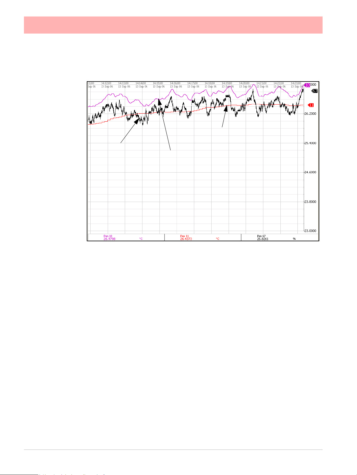
Figure 4.2 Effects of Damping and Rolling Average example
Input signal
(Pen 67)
Damping on input signal
(Pen 10)
Rolling Average of input signal
(Pen 11)
Note: the Damping (Pen 10) has been offset for this
example to be able to see the damping effect clearly
• Linearisation Tables (Ohms, V olt s and Amps only) - Select a table from the drop down
list if required.
• Use Pen Scale - Toggle On and Off, this is enabled by default. Analogue # defaults to
the corresponding Pen #, eg. A1 will default to Pen 1. If you change A1 to display
another pen scale eg.Pen 3, you must go into Pen 3 and change the maths to A1.
This will ensure that Pen Scale 3 will display A1 input. With this enabled the Engineering zero and span is the same as the pen scale. Disable this and the Engineering zero
and span will not reflect the pen scale. When disabled, see Eng. Span & Eng Zero bullet
points below.
This is not available when using Linearisation Tables.
See “Linearisation Tables” on page 81.
• Units - (Ohms, Volts and Amps only). This is the Units of Measurement for each input.
Select and enter a value. Max 13 characters. For Thermocouple and Resistance Thermometer units, see
• Label - Select and enter a identification label for the input. Select and enter a label. Max
15 characters.
• SQRT Extract - (Volts and Amps only). Toggle On and Off. The Square root extraction
in the analogue input is used to linearise certain sensors that have a non linear output for example in the calculation of flow. So when you check the Square root extraction in
the Analogue input section it carries out the following calculation. It ratios the analogue
input range that you set, to 0 to 1. So any sensor input is represented by a number from
0 to 1. We then take the square root. We then re ratio the result back to the user set
range.
“Localisation” on page 136.
74 43-TV-25-41 Iss.4 GLO May 2015 UK
Page 83

• Sensor Comp - Sensor Compensation may be required to improve accuracy on a sub
range. This is an adjustment to the value of the signal input on each channel, based on
the Engineering units settings. Choose from Single Point, Dual Point or Multi Point Cal,
see “Sensor Compensation” on page 351
• High Limit - Available when Range is User Defined. Select and enter the high limit
value.
• Lower Limit - Available when Range is User Defined. Select and enter the lower limit
value.
• RT Ty pe - Only availa ble when T y pe is set to RT (Res istance Thermometer). Sele ct this
for a list of available RT types.
• Burnout Type - Only available when Ty pe is set to TC (Thermocouple). Toggle
between Active and Passive. Active means it will send out a current to the TC. Set to
Passive means it takes a reading without sending out a current. The T/C is wired differently for Active and Passive Burnout (see
wiring,” on page 31
recorder)
Active Burnout checks the health of the thermocouples every 30 seconds, if your process requires continuous check of the thermocouples to see if they are in burnout you
should use Passive Burnout. Active burnout is an implementation of thermocouple
health and provides error warning messages for a range of thermocouple activity/failure
conditions. Passive burnout does not provide any error warning messages.
If the thermocouple wiring changes and the channel is set to Active, select Passive and
Commit the change. Then return to the menu and select Active and Commit the change
to update burnout settings.
.
). (Active Burnout is not available for the eZtrend GR
Figure , “Figure 2.16 Input signal
• Show Burnout - Only available when Type is set to TC. Toggle betwe en Upscale and
Downscale Burnout.
• TC Ty pe - Only available when Type is set to TC. Select this for a list of available TC
types.
• CJ Comp - Only available when Type is set to TC. Select this for a list of available CJ
Compensation. See
• • Int Automatic - Uses the cold junction sensor in the recorder as a variable reference temperature
• • Ext 0 Deg C - Assumes the cold junction is held at 0
ence, external to the recorder
• • Ext with Spec Temp - Uses a reference junction held at a constant temperature. Specify the temperature that the cold junction sensor is to be set at.
• • Ext Input - Use a thermocouple or resistance thermometer from another channel to measure the cold junction sensor
• External Input - Only available when CJ Compensation is set to Ext Input. Select the
input required as an external input.
• Eng. Span - (Ohms, Volts and Amps only). Only available when not using “Use Pen
Scale” option. This is the highest value of the engineering range and corresponds to the
top of the input range. Select and enter a value using the on-screen keyboard.
• Eng. Zero - (Ohms, Volts and Amps only). Only available when not using “Use Pen
Scale” option. This is the bottom of the engineering scale and represents the bottom of
the input scale. Select and enter a value using the on-screen keyboard.
“Thermocouple CJC Compensation” on page 338.
C to provide a 0mV refer-
• Demo Setup - Only available if there is no Analogue Input card fitted. Examples of various inputs are available without having an actual signal input coming into the recorder.
43-TV-25-41 Iss.4 GLO May 2015 UK 75
Page 84

• • Demo Type - Select this for a list of available Demo Type inp uts.
The Analogue Out screen
displays all the available
Analogue Output channels.
Each channel displays its
individual settings.
Select a numbered channel
to edit the configuration of
each output
Menu path to current menu
• • Cycle Time - Enter the Cycle T ime, in seconds, of the Demo Input. Select and
use the on-screen keyboard.
• • Add Noise - This is to Add Noise to the Demo Input as a percentage value.
Select and use the on-screen keyboard.
When the configuration is complete select the Finish button to Commit, Discard or Commit
Later. Select the Back button to return to the previous menu.
*Thermocouple Wiring Changes.
If the recorder is set to Active, select Passive and Commit the change. Then return to the
menu and select Active and Commit the change.
Analogue Out Menu
(Not available for the eZtrend GR recorder).
(Main Menu > Configure > Setup > Edit Setup> Field IO > Analogue Out)
Only available when an Analogue Out card is fitted as an option, 2 or 4 outputs are available
per card.
The outputs are factory calibrated to meet the published specification and cannot be field
calibrated.
Refer to connection details and “Analogue Output Channel Numbers” on page 35
Press the Analogue Out button to display all the analogue outputs available. Click on individual Analogue Out number to set up each channel profile.
• Enabled - Toggle On and Off.
• Allow Overrange - Toggle On and Of f. Disabled as default, this will allow the output signal to go overrange to 21mA, if disabled the maximum is 20mA.
• Transmit Pen - Eg. Select a pen to output 4-20 mA loop. This will take the scale value
from the pen it is transmitting and convert to 4-20mA output signal. eg if the scale is 050% this signal will fit the scale so 4mA = 0% and 20mA = 50%. For 0-20mA output signal with the same 0-50% scale, this would read 0mA = 0% and 20mA = 50%.
76 43-TV-25-41 Iss.4 GLO May 2015 UK
Page 85

• Output - Select either 4-20mA or 0-20mA.
• Label - Select and enter an identification label. Select and use the on-screen keyboard.
Up to 16 characters.
When the configuration is complete select the Finish button to Commit, Discard or Commit
Later. Select the Back button to return to the previous menu.
Alarm / Digital IO
(Main Menu > Configure > Setup > Edit Setup> Field IO > Alarm/Digital IO)
The Alarm/Digital IO button will display all the digital inputs/outputs available. Click on each
individual Alarm IO or Digital IO number to set up each channel profile.
Cards available are:
2 types of Alarm Relay cards
• 4 Alarm Relay Output
• 8 Alarm Relay Output with 2 Digital Inputs
2 types of Digital IO cards
• 8 Digital Inputs or Outputs
• 16 Digital Inputs or Outputs.
(Not available for the eZtrend GR recorder).
Alarm Relay Card
4 Alarm relay output card or 8 Alarm relay Output with 2 Digital Inputs (6 fixed outputs and
2 configurable Digital Input or output) cards.
Digital IO Card
There are 8 or 16 Digital channels per card that can be setup as inpu ts or outp uts. The Digital I/O card also has 4 channels that can be set as pulse inputs (channels 1 to 4). The operating frequency for pulse inputs on the Digital I/O card is 1kHz max.
Input: Low < 1V, High >4.5V to <10V DC (9V to 20V p-p AC) or Volt free input: Low = short
circuit, High = open circuit.
To view and log a channel selected as a Pulse input, set up an extra p en with a Maths func tion of LPULn in Edit Maths in the Pens menu. For more informatio n see “Appendix B:
Maths Expressions” on page 321.
For connection details see For connection details See “Alarm Relay Channel Numbers”
on page 39
43-TV-25-41 Iss.4 GLO May 2015 UK 77
Page 86

For all cards select an Alarm/Digital # to display the configuration menu. Each Alarm/Digital
The Digital IO screen
displays all the available
channels that can be set
up to be digital inputs or
outputs.
Each channel displays
its individual settings.
Select a numbered
channel to edit the configuration of each input
or output.
Menu path to current menu
NOTICE
Outputs that are set to Single Pulse should not be used as a part of
a maths expression as it can cause spurious values.
has a list of menu items to be configured.
• Enabled - Toggle On and Off
• Digital Type - Set to Output Relay contact (Power) for the Alarm Relay cards. Toggle
between Input and Output or Pulse Input for the Digital IO card. On the 4 Relay Alarm
card, only output type is available. Channels 1 to 6 on the 8 Alarm Relay card are outputs, channels 7 & 8 can be either inputs or outputs.
Note: Pulse Input only available on channels 1 to 4 for slot G, 17 to 20 for slot H
and 33 to 36 for slot I.
• Output - (Output only). The relay outputs can be set to be either Latched or Single
Pulse. A Latched relay will be maintained in its active state until the trigger source has
returned to a non-alarm state (unless acknowledged). For Single Pulse the relay will go
active for a period of time, specified by the user, then return to a non active state. The
time out period remains independent of the length of time the active state remains. If
the output is set to Single Pulse, when the alarm is activated the signal will display a
single pulse for the duration set. See Pulse Duration. The alarm will trigger again when
it goes back into an active alarm state.
• Pulse Duration - (Output only). Available when Single Pulse is selected as an Output.
Specify the pulse length in seconds from 0.1 (100ms) to 6480 (108 minutes) in 0.1 second increments. Select and enter the pulse length.
• Failsafe - (Output only). Toggles On and Off. Each relay channel can be independently
selected with the fail safe option. This will invert the state of the relay output. With Failsafe Off, normally open (NO) relays have open contacts when the power is off, and
open contacts when there is no active alarm. The contacts will close when an associated alarm goes active. With Failsafe On, normally open relays have closed contacts
when the recorder is powered on and there are no open active alarms, and the contacts
open with an alarm active or when the power is removed.
Positions” on page 306.
78 43-TV-25-41 Iss.4 GLO May 2015 UK
See “Failsafe Relay
Page 87

• Label - Select and enter an identification label. Up to 16 characters.
• Active Label - (Input and Output only). This is the label that is shown when an alarm
becomes active. Select and enter a label. Not available for Pulse Input. Up to 12 characters.
• Inactive Label - (Input and Output only). This is the label that is shown when an alarm
becomes inactive. Select and enter a label. Not available for Pulse Input. Up to 12 characters.
• Reports To - This will acknowledge the Alarm/Digital IO to a selected destination.
Select User message to add the Digital IO occurrence to the messages list only. Select
Mark On Chart to display the occurrence on a chart and to the messages list.
When the configuration is complete select the Finish button to Commit, Discard or Commit
Later. Select the Back button to return to the previous menu.
43-TV-25-41 Iss.4 GLO May 2015 UK 79
Page 88

Pulse Input
The Pulse Input screen
displays all the available
pulse input channels that
can be set up.
Each channel displays its
individual settings.
Select a numbered channel to edit the configuration of each Pulse input.
Menu path to current menu
(Not available for the eZtrend GR recorder).
(Main Menu > Configure > Setup > Edit Setup> Field IO > Pulse Input)
Only available when a Pulse Input card is fitted as an option. The Pulse Input card operate s
up to a frequency of 25kHz max. See “Pulse Input Channel Numbers” on page 36.
Input: Low < 1V, High >4V to <50V DC or Volt free input: Low = short circuit, High = open
circuit.
If a Pulse input card is fitted in slot A the first 4 pens will display the maths function of HPULn
in Edit Maths in the Pens menu as default to display the pulse read ing. For more information
see “Appendix B: Maths Expressions” on page 321.
Press the Pulse Input button to display the available pulse inputs.
Click on individual Pulse Input number to set up each channel profile.
• Enabled - Toggle On and Off.
• Hertz - Fixed as Frequency Measure (in Hertz).
• Update Rate - Fixed at 1Hz
• Label - Select and enter an identification label for the pulse input. Select and enter a
label. Up to 16 characters.
When the configuration is complete select the Finish button to Commit, Discard or Commit
Later. Select the Back button to return to the previous menu.
80 43-TV-25-41 Iss.4 GLO May 2015 UK
Page 89

Linearisation Tables
(Main Menu > Configure > Setup > Edit Setup> Field I/O > Linearisation)
Linearisation Tables - To be used with Analogue Input type Volts, Amps or Ohms.
These are user defined tables that can be set up to allow a non-linear input signal to be displayed on the recorder. By entering a set of non-linear signal input values (X) into the linearisation table, the recorder will use the table to generate linear output (Y) in engineering
units, to be displayed and/or log on the recorder.
• Select the next available table and rename it for ease of identification by selecting the
name button.
• Select the Values button to take you to the start of a new table. Press the Add button to
produce the first line. Up to 50 points are availablie in the table. More than one set of
points are required to do the conversion.
• Click into the text entry boxes under the X and Y boxes and enter the required values
(or leave it if your table starts at 0). The Signal Input (X) goes in the first column and the
Engineering units (Y) in the second column.
• T o add a line at the bottom, click on Add. To ad a line above or below, click on a line and
use the Insert Above and Insert Below buttons. To delete a line, click in the line and
select Delete.
• When you have finished your table select the tick box, this will also verify the table and
produce a Data Error box if there are any problems.
Data Error box
If incorrect vales are entered a Data Error box will appear saying “Data line * is invalid”. This will appear
when you select the tick box at the bottom of the screen. The error box will indicate which line has the
error. There may be more than one error in the table, if so the data error message box will appear for
each error starting from the top line down going to the next as each error is fixed.
43-TV-25-41 Iss.4 GLO May 2015 UK 81
Page 90

Linearisation Table examples
0 2 4 6 8 10
0
2
4
6
8
10
X
(Signal Input)
Y
(Eng. Units)
Figure 4.3 Example of a 0-10V non-linear input signal
Figure 4.3 shows an example of a set of non linear signal inputs (X) and the required values
in engineering units (Y) that have been entered into a linearisation table. The y would produce the following curve.
A straight line is drawn between each point, as shown by the co ntinuous (red) line in Figure
4.3. For a more accurate curve, as shown by the dotted line (blue), add more data points
into the linearisation table.
The Linearisation tables that you set up here can the n be used in the “Analogue In Menu”
on page 73
If the full input range is greater than the range u sed in the linearisation tables then the sig nal
will carry on following the slope of the last two inputs. For example if we had a -50 to +50V
range and just used the 0 to 10V linearisation table then the signal would look like Figure
4.4.
If the Analog input has been set to millivolts, and that the span is greater or equal to 1000
mV, then the linearisation table X values should be specified in Volts
82 43-TV-25-41 Iss.4 GLO May 2015 UK
Page 91

-50 -40 -30 -20 -10 0 10 20 30 40 50
-50
10
20
30
40
50
-40
-30
-20
-10
0
The last two points are used to follow the slope for the rest of the signal.
At the bottom of the 0-10V table the last two inputs are X=0, Y=0 and X=2, Y=6.
At the top of the 0-10V table the last two points are X=8, Y=9.8 and X=10, Y=10.
Figure 4.4 shows these last two inputs at the top and bottom of the 0-10V signal.
Figure 4.4 Linearisation ta ble used for part of the range
Y (Eng.
Units)
X (Signal
Input)
43-TV-25-41 Iss.4 GLO May 2015 UK 83
Page 92

Pens Menu
The Pens screen displays
all the available pens.
Each pen displays its
scale settings.
Select a pen number to
edit the setup of each pen
including the Scale,
Logging, Alarms and
Totaliser
Menu path to current menu
(Main Menu > Configure > Setup > Edit Setup> Pens)
Select the Pens button to display all the pens available.
Click on individual pen number to set up each pen profile.
• Enabled - Toggle On and Off.
• Tag - Select and use the on-screen keyboard to type in an identifier for the pen. Up to
47 characters.
• Description - (Screen Designer screens only) Enter a screen description in this field
that will then be displayed on the Screen Designer screen.
• Maths Type - Analogue signals may have a mathematical calculation performed on
them before they are represented as a pen. Basic maths is standard in all recorders.
Full Maths or Math Scripting are options that must be activated.
See “Options” on
page 196.
• Edit Maths - Edit the Maths for this particular pen. For details see “Appendix B:
Maths Expressions” on page 321.
• Scale - Select Scale to go to a sub menu to set up the scale parameters. See “Scale
Menu” on page 85
• Logging - Select Logging to go to a sub menu to set up the logging configuration. See
“Logging Menu” on page 86
• Alarms - Select Alarms to go to a sub menu to set up the alarm profile. See “Alarms
Menu” on page 88
• Totaliser - Select Totaliser to go to a sub menu to set up the totaliser settings. See
“Totaliser Menu” on page 90
• RAV - This will display the Rolling Average for this pen. The recorder takes an average
of the number of samples entered.
For example: a 1 hour rolling average made up of 1 minute averages it would be 60
seconds per sample with 60 samples, and you can increase the time span accordingly,
so 1440 samples at 60 seconds per sample would give you a 24 hour rolling average
made of 1 minute averages.
Enable the RAV function. Enter the Number of Samples.
Then enter the Sample Interval, or how often a reading is taken, in seconds.
84 43-TV-25-41 Iss.4 GLO May 2015 UK
Page 93

Prefill works as follows, if you setup a 60 sample rolling average a 10 second samples
Select the Scale button to take you to the Scale menu
Menu path to current menu
that will create a 10 minute rolling average, with each sample being accumulated as an
average from the current recorder processing rate (10Hz say), so each 10 second sample is added to a queue of 60 samples, and each 10 seconds the new rolling average is
calculated. The prefill simply takes the current pen value and fills the queue with that
average, causing the "damping" effect to be baselined at the current reading. No prfill
will cause the first few samples to have a greater effect on the average, as they will not
be diluted by 60 samples but 1, 2, 3, 4 up to 60 after the 10 minutes.
Group - This pen can be allocated to a Group with other pens to display information, be used
for batch control or run repo rt s o n gro u ps of pe n s. Se le ct t his to display the list of available
Pen Groups. If you select a group here this pen will be added to it. Maximum24 pens per
group for Multitrend GR, 16 for DR Graphic and Minitrend GR and 8 for eZtrend
GR. The group can then be renamed, to rename these groups, see “Groups” on
page 142. Groups are used as a part of the Batch system, see “Batch Menu” on
page 138.
Groups are also used as a part of AMS2750, see “AMS2750 Process Menu” on
page 379.
• Colour - Each Pen has a Default Pen Colour but this can be changed if required. Select
and use the colour palette to set the pen colour.
• Trace Width - Select and set the Trac e Width for this pen when it is displayed on a
chart. The default trace width is 1 with a maximum of 7.
When the configuration is complete select the Finish button to Commit, Discard or Commit
Later. Select the Back button to return to the previous menu.
Scale Menu
(Main Menu > Configure > Setup > Edit Setup> Pens > Scale)
Individually configure each scale per pen in the scale menu.
Click on Scale to set up each scale profile per pen.
• Units - Scale measurement Units. Select this and enter the units. Up to 16 characters.
• Span - This is the highest value of the scale. Select to enter the Span value.
43-TV-25-41 Iss.4 GLO May 2015 UK 85
Page 94

• Zero - This is the bottom of the scale. Select to enter the Zero value.
Normal
Scientific
Pen Logging can be set to log as Continuous or Fuzzy
Menu path to current menu
• Scale Type - Toggle between Linear or Logarithmic (Log).
• Divs Select - Only available with Linear Scale Type. Toggle between Auto or User
Defined.
• Major Divs - Only available when Divs Select is set to User Defined. Select and enter
the major division position.
• Minor Divs - Only available when Divs Select is set to User Defined. Select and enter
the minor division position.
• Start Decade - Only available when the Scale Type is set to Log. Select and enter the
start value of the first decade.
• No. Decades - Only available when the Scale Type is set to Log. Select and enter the
number of decades required. Max 99 decades (although not all will be displayed on the
recorder).
• Numb Format - Displays the Notation of the number format, Scientific or Normal.
• • Notation - Toggle between Scientific or Normal
number format. The scientific format displays the
value to the power of 10 shown here. Notice the
value has been rounded up.
• • Auto - Toggle Betwee n Automatic number formatting and User Defined.
• • After Decimal - Only available when User Defined is selected. Select and
enter the number of decimal places. (up to 15 decimal places)
When this pen setup is complete go back to the Pen # menu and complete the pen setup
for all other pens.
Logging Menu
(Main Menu > Configure > Setup > Edit Setup> Pens > Logging)
86 43-TV-25-41 Iss.4 GLO May 2015 UK
Page 95

Click on Logging to set up each logging profile per pen.
• Enabled - Toggles On and Off to activate or de-activate logging for this pen.
• Type - Toggles between Continuous or Fuzzy logging. Continuous logs every value
based on the Method chosen (Sample, Average or Max/Min).
Fuzzy Logging has been developed as a secure data storage technique which has a
self teaching data storage algorithm so the recorder stores data at a variable rate to
match the process being monitored. Fuzzy Logging has intelligent resources to enable
the most effective and efficient way of using the scan rate, storage capacity and recording time.
• Rate Units - Set the Units for the logging rate to be displayed. Select and choose the
logging rate units from the drop down menu.
• Rate - This is the speed at which data is required to be logged.
If the Millisecond option is selected as the Rate Units for the logging, then a drop down
menu of options will appear. When all other Rate Units are selected a keypad will
appear for user entry. Fastest rate is 20mS and slowest is 60 hours.
• Alarm Rate Units - Only available if the logging Type is set to Continuous. Set the Units
for the Alarm logging rate to be displayed. Select and choose the alarm logging rate
units from the drop down menu.
• Alarm Rate - Only available if the logging Type is set to Continuous. This is the new
logging rate used when this pen goes into an active alarm state. To enable this feature
to change the logging rate in an alarm state, see Change Log in the Alarms menu.
If the Millisecond option is selected as the Alarm Rate Units for the logging, then a
drop down menu of options will appear. When all other Alarm Rate Units are selected
a keypad will appear for user entry.
See “Appendix F: Fuzzy Logging” on page 345
• PreTrigger - activate pre-triggering for that pen, any alarm on that pen will cause the
pre-trigger system to be activated. Only the first 16 pens can be configured for pre-triggering.
For details on the Pre-Trigger function and configuration for the pre-trigger time is held
in the recording menu in the setup configuration under a separate button called pre-trig-
“Pre-Trigger” on page 151.
ger,
The alarm rate for each pen will be used for the pre trigger rate. The alarm rate must be
set to less than 10 seconds per sample for pre-triggering to operate.
Pre trigger will only operate when the logging is in continuous sample mode, pre-triggering will not be available with fuzzy logging or Max Min.
• Method - Only available if the logging Type is set to Continuous. Select from a list of
Methods.
Sample: logs the last sampled reading.
Average: logs the average of all the samples taken since the last log.
Max/Min: logs the highest and the lowest of the sampled readings since the last log.
• Align - Only available if the logging Type is set to Continuous. Select and enter a value
from the list to align the logging at specified intervals. This will hold the start of logging
until the aligned time selected occurs based on the recorders real time clock.
• Auto Fit - Only available if the logging Type is set to Fuzzy . Toggles On and Off. AutoFit
ensures that the last sampled data point is logged before the signal goes out of the tolerance set in Band 1 or Band 2. When displayed on a graph, the input signal will automatically fit to this last logged point. This gives a better fit for stepped input changes.
43-TV-25-41 Iss.4 GLO May 2015 UK 87
Page 96

• Band 1 % - Only available if the logging Type is set to Fuzzy. This is where the toler-
The Pen Alarms screen displays up
to alarm set points per pen.
Each alarm displays its individual
alarm setting.
Select an alarm number to edit the
setup of each alarm
Menu path to current menu
ance is set for the input signal. Specify, as a percentage of the scale range, the tolerance band allowed above and below the input signal. Select and enter a value.
• Fuzzy Band 2 - Only available if the logging Type is set to Fuzzy. Toggles On and Off.
This is to enable a second tolerance to be set, configure it to be On to activate. Only
used in conjunction with Autofit On, to specify the Band 2 %.
• Band 2 % - Only available if the logging Type is set to Fuzzy. This is where a tighter tol-
erance can be specified which must be set within the limits of Band 1. Specify , as a percentage of the scale range, the tolerance band allowed above and below the input
signal. Select and enter a value.
When the setup is complete go back to the Pen # menu and complete the pen setup.
Alarms Menu
(Main Menu > Configure > Setup > Edit Setup> Pens > Alarms)
This is for setting up alarms on this pen only, a maximumu of 6 alarms per pen are allowed .
Select the first available alarm eg. Alarm 1 and configure each alarm.
When an alarm has been configured an Alarm Marker or Pen Pointer will appear for each
alarm depending on the type of process screen. See “Alarm Markers” on page 236
• Enabled - Select Enable to see a list of ways to enable or disable the alarm. Disable,
Enabled Always or Dig Enabled.
• Enabled by Digital - Only available when Enabled is set to Dig Enabled. Select and
choose which digital signal(s) will enable this alarm (on this pen only).
• Type - Select this to display a list of different types of Alarms. High, Low, Deviation ,
Rate Up or Rate Down. Set a High alarm to activate when the signal goes above the
Alarm Level, or set a Low alarm to activate when the signal goes below the Alarm
Level. Deviation is the how far this pen can deviate from the Ref Pen before triggering
88 43-TV-25-41 Iss.4 GLO May 2015 UK
Page 97

an alarm. See Deviation Level and Ref Pen.
Rate Up and Rate Down Alarms are used to trigger an alarm when the signal changes
a defined amount over a specified time. See Deviation Level and Time Period.
• Level - Select and enter a figure at which the alarm is to be triggered.
• Deviation Level - Only available when Alarm Type is set to Deviation, Rate Up or Rate
Down. Select and use the numeric keypad to enter the amount of deviation (in engineering units). For Deviation enter the amount of deviation allowed on a designated pen
(Ref Pen) before an alarm is triggered.
For Rate Up and Rate Down enter, as a percentage, how far the signal can deflect
before an alarm is triggered.
• Ref Pen - Only available when the Alarm Type is set to Deviation. Select and enter the
pen that this alarm is referenced to. This works like an actual pen that dynamically
tracks a designated pen.
• Time Period - (Only available when the Alarm Type is set to Rate Up or Rate Down).
Enter (in seconds) how long the signal is allowed to deviate, at the specified deviation
level, before an alarm is triggered.
• Tag - Enter a tag or name to identify this alarm. Up to 17 characters.
• Allow Change - If activated this will allow quick configuration changes to this alarm
level from the Alarms > Configure button on the Main Menu.
This does not change the original setup.
• Relays Out - Select and choose which Relay Output(s) is triggered by this alarm (on
this pen only). The Fixed button will use the common relay output on the power board
(24V relay). (Common relay output is not available for the
eZtrend GR recorder).
• Latched - A latched alarm will maintain in its active state until the trigger source has
returned to a non-alarm state and the alarm has been acknowledged. A latched alarm
will continue to flash, if an alarm marker or pen pointer is displayed, until it is acknowledged and in a non-alarm state. See “Acknowledging Alarms” on page 341 A
Reflash option is available to keep the alarm flashing whilst in an alarm state even after
it has been acknowledged. See Reflash.
• Change Log - Toggles On and Off. Select this to change the Log speed when an alarm
occurs. The Log rate changes when alarm is active and stays at the alarm rate for as
long as the alarm is active then returns to the normal logging rate. Set up the new alarm
logging rate in Alarm Rate in
• Mark Chart - Toggles On and Off. Selecting On will place a Mark on the Chart with
automated messages when the alarm becomes active. From the position of the Mark
on Chart the chart background colour will change to show it is in an alarm state.
• Email Alarm - Enable this to send an email when any alarm is triggered on this pen.
“Logging Menu” on page 86.
This function is a firmware option that is activated from the Factory menu >
“Credits” on page 131.
• Recipients - Only available when email has been enabled. Select your recipients from
the list provided. Email addresses and Server names must be entered in
“Email” on
page 106.
• Hysteresis - (not available for Deviation). Toggles On and Off. When this is activated,
you can set a tolerance level for an alarm. It allows a specified percentage value of the
span of the scale to be added to the alarm level.
• Hyst Level % - (not available for Deviation alarm). Enter as a percentage of the span of
the scale. This is how much tolerance the signal can have past the set alarm activation
43-TV-25-41 Iss.4 GLO May 2015 UK 89
Page 98

point until the alarm is de-activated. The example in Figure 4.5 shows the alarm acti-
50%
40%
0%
100%
Low Alarm Level
10% Hysteresis level
Alarm de-activated
at this point
Alarm activated
at this point
Figure 4.5 Hysteresis Level
NOTICE
IEEE floating point numbers with large unit factors beyond the IEEE range may incur
incremental errors, specially if incrementing by a small amount each time. If this is your
type of application a work around would be to set the Unit factor to 1 and then divide
the total by your original unit factor.
vating at 40% which is the set low alarm level. The alarm is not de-activated until the
signal is at 50%, which is 10% past the set alarm level. So the Hyst Level % would be
set to 10%. Reverse the process for a high alarm.
• Damping - Toggles On and Off. Damping is a time delay that works going into alarm
only. When switched On, the alarm level must be breached for a specific period of time
before an alarm is triggered.
• Damping Time - Set the amount of Damping time in seconds. Damp level can be from
1 seconds to 64800 seconds.
• Reflash - Toggles On and Off. Activate this to re-enable an active alarm that has been
acknowledged. Set the Reflash Time.
• Reflash Time - Only enabled when Reflash is active. Set the time period after the alarm
has been acknowledged for the alarm to reflash if it is still in an alarm state.
When the setup is complete go back to the Pen # menu and complete the pen setup.
Totaliser Menu
(Main Menu > Configure > Setup > Edit Setup> Pens > Totaliser)
The Totals option must be active to use this option. See Table 7.1, “Firmware Options,”
on page 241.
To Start, Stop, Reset and View Totals, see “Totals” on page 190.
The Totaliser function is normally associated with flow monitoring applications. The input to
the recorder would be a measure of flow rate (eg. In litres per second) and the total amount
that has flowed over a specified time period. Multiple totalisations are possible with the use
of extra pens (firmware Credit option). Totalisation values are 10 digits plus exponent.
90 43-TV-25-41 Iss.4 GLO May 2015 UK
Page 99

Click on Totaliser to set up the totalising profile per pen .
Menu path to current menu
Totaliser menus showing Normal and Sterilisation types
Select Totaliser from the Pen screen to display the totalising setup menu
• Enabled - Toggles On and Off to activate or de-activate totalising for this pen.
• Type - Select this for a list of Types of totalising. Normal or Sterilisation. Normal totaliser
function is usually associated with flow monitoring applications.
Sterilisation* is where items are subjected to heat over a period of time. Each pen can
be totalised according to the Fo or Po sterilisation* function at 250 °F (121.11°C). The
Standard Reference Temperature and Thermal Resistance (Z Value) are adjustable. All
temperature limits are adjustable. Start temp, Reference temp and Z factor are all user
defined, allowing support for many different types of sterilisation applications. See
“Sterilisation” on page 93
• Tag - Select and enter an identifier for the pen. Up to 17 characters.
• Add to Msgs - Toggles On and Off. Select this to add a totaliser to the messages
screen. Eg. Total1: Total 1 Reset
• Units - Normal Totaliser only. This is the Units of Measurement for the totaliser. Select
and enter the units. Up to 12 characters.
• Time Factor - Normal Totaliser only. Time factor – Totaliser adds a value once per second, so you need to Divide by this factor. For example:
If your flow meter is in units/second Time factor is 1.
If your flow meter is in units/minute, the unit will DIVIDE by the time factor, in this case
60 – so every 1 second, 1/60th of the unit is added.
If your flow meter is in units/hour, the unit will DIVIDE by the time factor, in this case
3600 – so every 1 second, 1/3600th of the unit is added.
• Unit Factor - Normal Totaliser only. The Totaliser adds the engineering unit from the
instrument, onto the total (after the time factor is applied). You then need to Divide by
the unit factor. For example:
43-TV-25-41 Iss.4 GLO May 2015 UK 91
Page 100

If your flow meter is in litres/time and you want to Totalise in litres – there 1 litres in 1
litre, so your unit factor would be 1, so every 1 second 1/1 unit is added.
If your flow meter is in litres/time and you want to Totalise in Cubic meters – there are
1000 litres in 1 cubic meter, so your unit factor would be 1000, so every 1 second 1/
1000th of a unit is added.
• No Backflow - Normal T otaliser only . If the flow reading should go into a negative value,
eg. The flow meter has been switched off, and “No Backflow” is inactive, the totaliser
will subtract from the total value. When “No Backflow” is active any negative values are
ignored and the total value is held while the flow meter is off until the backflow level is
exceeded.
• Backflow Level - Only active when No Backflow is set. Set the level at which totalising
will stop if the signal flow goes below this limit and if the No Backflow option is active.
• Restrict Range - Normal Totaliser only. Toggles On and Off. When active the totaliser
restarts at Min range once it reaches Max range.
• Min. Range - Normal Totaliser only. Only available when Restrict Range is active.
Select and enter the minimum limit for the totals to range to.
• Max. Range - Normal Totaliser only. Only available when Restrict Range is active.
Select and enter the maximum limit for the totals to range from.
• Use Remainder - Normal Totaliser only. Only available when Restrict Range is active.
Toggles On and Off. If the total exceeds the maximum range set, the total will reset to
the minimum range set. When Use Remainder is active, it will carry over any amount in
excess of the maximum range set.
• Temp Input Units - For Sterilisation, select the temperature input units.
• Start Temp - For Sterilisation, select the Start Temperature.
• Ref. Temp - For Sterilisation, select the Reference Temperature.
• Z Factor Temp - For Sterilisation, select the Z factor temperature
• Include Cooling - For Sterilisation, Include Cooling if required
• Completion Value - For Sterilisation, if cooling is not required, enter a Completion
Value. The totaliser will stop at this value.
• Reset at 16M - Enabled by default. The upper limit for the totaliser count is fixed to
16777215 to prevent an inaccuracy. The totaliser will get reset after this count.
To go above the 16M limit disable this function, but be aware that the count will add
some inaccuracies in the calculation above this upper limit, see
Table 4.2 on
page 93.
• Numb Format - Displays the Notation of the number format, Scientific or Normal.
• • Notation - Toggle between Scientific or Normal number format.
• • Auto - Toggle Betwee n Automatic number formatting and User Defined.
• • After Decimal - Only available when User Defined is selected. Select and
enter the number of decimal places. (up to 15 decimal places)
When the setup is complete go back to the Pen # menu and complete the pen setup.
92 43-TV-25-41 Iss.4 GLO May 2015 UK
 Loading...