

Page 1
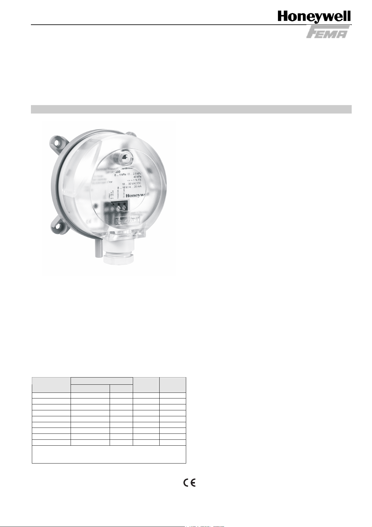
DPTM50-5000
3-WIRE DIFFERENTIAL PRESSURE TRANSMITTERS
WITH CURRENT AND VOLTAGE OUTPUT
SPECIFICATION DATA & MOUNTING INSTRUCTIONS
FEATURES
• Monitoring gaseous, non-aggressive media
• Piezo-resistive pressure transducer
• Up to 40 kPa (60 kPa) overload capacity
• Rugged design; protection class IP54
• Easy installation and wiring connection
• Measurement range adjustable by jumper
• Response time adjustable by jumper
• Output signal adjustable by jumper
• Re-zeroing possible by pushbutton
NOTE: These sensors are not suitable for use in
installations under periodic inspection by the U.S.
Food and Drug Administration.
GENERAL
The differential pressure transmitters of the DPTM series are
used for measuring differential pressure, positive pressure,
and vacuum. The transmitters are suitable for:
• air-conditioning,
• building automation,
• environmental protection,
• valve and flap control,
• filter and blower monitoring,
• fluid and level monitoring, and
• control of air flows.
Models
order no.
DPTM50 -50...0...+50 Pa1) n.a. 20 kPa 40 kPa
DPTM110 -100...0...+100 Pa1 n.a. 20 kPa 40 kPa
DPTM550 -500...0...+500 Pa1) n.a. 20 kPa 40 kPa
DPTM1100 -1 kPa...0...+ 1 kPa2) n.a. 40 kPa 70 kPa
DPTM100 0...100 Pa1) 0...250 Pa 20 kPa 40 kPa
DPTM250 0...250 Pa1) 0...500 Pa 20 kPa 40 kPa
DPTM500 0...500 Pa1) 0...1 kPa 20 kPa 40 kPa
DPTM1000 0...1 kPa2) 0...2.5 kPa 40 kPa 70 kPa
DPTM5000 0...5 kPa3) 0...10 kPa 60 kPa 120 kPa
1)
Temperature error at 0…50 °C ≤ ± 5% of FS
2)
Temperature error at 0…50 °C ≤ ± 2.5% of FS
3)
Temperature error at 0…50 °C ≤ ± 1% of FS
pressure range
1
(pre-set)
2
overload
capacity
bursting
pressure
SPECIFICATION
Supply voltage 18...30 Vac/dc, 50/60 Hz
Output signal 0...10 Vdc, 4…20 mA
Pressure medium Air, non-aggressive gases
Working temperature 0...50 °C
Linearity and hysteresis error ≤ ± 1.0% of FS
Temperature error at 0...50°C See section "Models"
Storage temperature -10...+70 °C
Humidity 0...95% rh, non-condensing
Repetition accuracy ≤ ± 0.2% of FS
Response time 1 s (switchable to 100 ms)
Process connection 6 mm hose pipe
Electrical connection Screw terminal block for wire
up to 1.5 mm²
Housing material ABS and POM
Cable entry M20x1.5 (polyamide)
Protection class IP54 as per EN60529
EMV EN60770, EN61326
Weight approx. 130 g
® U.S. Registered Trademark EN0B-0466GE51 R1007
Copyright © 2007 Honeywell Inc. • All rights reserved
Page 2
DPTM50-5000 DIFFERENTIAL PRESSURE TRANSMITTERS WITH CURRENT/VOLTAGE OUTPUT
j
j
A
j
FUNCTION
DPTM50…5000 Three-Wire Differential Pressure Transmitters are equipped with an integrated piezo-resistive
pressure transducer. The pressure to be measured is applied
to and thus deflects a thin membrane made of monosilicon.
The membrane's semiconductor resistors (arranged to simultaneously compensate for the temperature response) detect
this deflection and generate an electrical output signal. The
output signal is converted into the 0…10 V or 4…20 mA
analog signal which changes (within the specified error limits)
in proportion to the applied pressure.
NOTE: The devices are factory pre-set to pressure range 1.
This can be changed (except for +/- models) to
pressure range 2 by removing the corresponding
jumper (see Fig. 3).
NOTE: The devices are factory pre-set to a response time
of 1 second. This can be changed to 100 ms by
removing the corresponding jumper (see Fig. 3).
NOTE: The devices are factory pre-set to an output signal
of 0…10 V. This can be changed to 0…20 mA by
removing the corresponding jumper (see Fig. 3).
ACCESSORIES
DPSK: Included in delivery. Duct Kit, incl. 2 m of silicone
hose and two joining pipes
DPSL: Ordered separately. L-shaped mounting brackets
with screws.
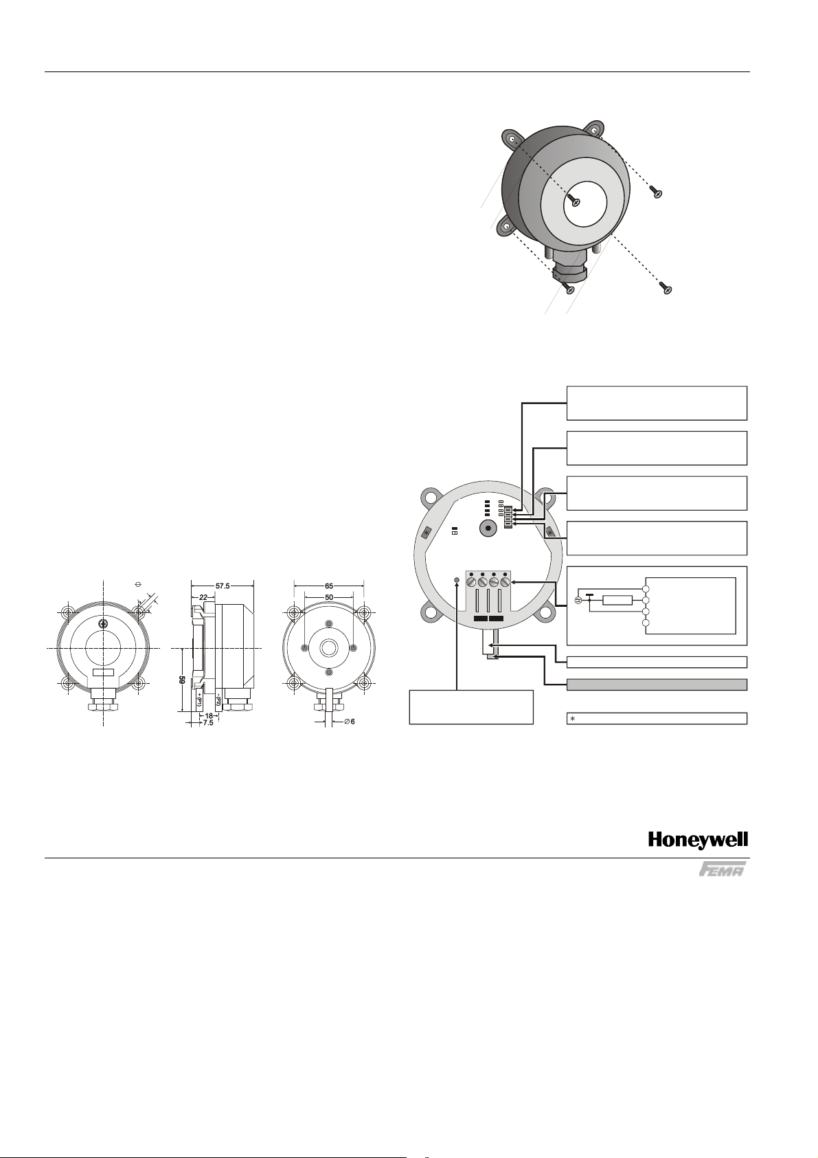
DIMENSIONS
4.5
8.5
MOUNTING
WIRING
Range:
high
low
Response:
fastmAslow
Mode:
Output:
V
Jumper yes
Jumper no
Differential Pressure Transmitter
2341
Fig. 2. Mounting
PRESSURE RANGE
jumper inserted = pressure range 1
jumper removed = pressure range 2
RESPONSE TIME
umper inserted = 1 sec
umper removed 100 msec=
NOT USED
NALOG OUTPUT
umper inserted = 0...10 V
jumper removed = 4...20 mA
1
2
LOAD
3
4
18...30Vac/dc
0...10 V / 4...20 mA
GROUND
DO NOT USE!
P2 (LOW PRESSURE)
IP 54
Fig. 1. Dimensions (in mm)
REZEROING:
Remove tubes and push
button approx. 5 sec.
Fig. 3. Wiring details
P1 (HIGH PRESSURE)
STORAGE POSITION FOR JUMPERS
Manufactured for and on behalf of the Environmental and Combustion Controls Division of Honeywell Technologies Sàrl, Ecublens, Route du Bois 37, Switzerland by its Authorized Representative:
Fema Controls
Honeywell GmbH
P.O. Box 1254
71099 Schönaich
Germany
phone: (49) 7031-637-02
fax: (49) 7031-637-850
http://www.honeywell.de/fema
Subject to change without notice.
EN0B-0466GE51 R1007
 Loading...