

Page 1
USA
CAN
MEX
D
03251549
USA CAN MEX
➔ www.docuthek.com
Operating instructions
Pressure switches for gas DG..T
© 2018 Elster GmbH · Edition 09.18
Cert. version 05.18
Translation from the German
Safety
Please read and keep in a safe place
Please read through these instructions
carefully before installing or operating. Following the
installation, pass the instructions on to the operator. This unit must be installed and commissioned
in accordance with the regulations and standards
in force. These instructions can also be found at
www.docuthek.com.
Explanation of symbols
• , 1 , 2 , 3 ... = Action
▷ = Instruction
Liability
We will not be held liable for damage resulting from
non-observance of the instructions and non-compliant use.
Safety instructions
Information that is relevant for safety is indicated in
the instructions as follows:
DANGER
Indicates potentially fatal situations.
WARNING
Indicates possible danger to life and limb.
CAUTION
Indicates possible material damage.
All interventions may only be carried out by qualified
gas technicians. Electrical interventions may only be
carried out by qualified electricians.
Conversion, spare parts
All technical changes are prohibited. Only use OEM
spare parts.
Checking the usage
Gas pressure switches DG..T for monitoring increasing and decreasing gas or air pressure.
DG..T,
DG..FT
DG..HT,
DG..NT
DG..ST NH
DG..NT and DG..HT lock off after switching. They
can be unlocked using the manual reset.
This function is only guaranteed when used within the
specified limits– see page5 (Technical data). Any
other use is considered as non-compliant.
Type code
Code Description
DG Gas pressure switch
6 – 500 Max. setting in mbar
F*
H*
N*
S*
T T-product
G With gold-plated contacts
-2
-4
-9
1
2
K2
T2
Red/green pilot LED for 110 to 230 V AC
N
A External adjustment
* If “none”, this specification is omitted; DG..T
switches with rising pressure.
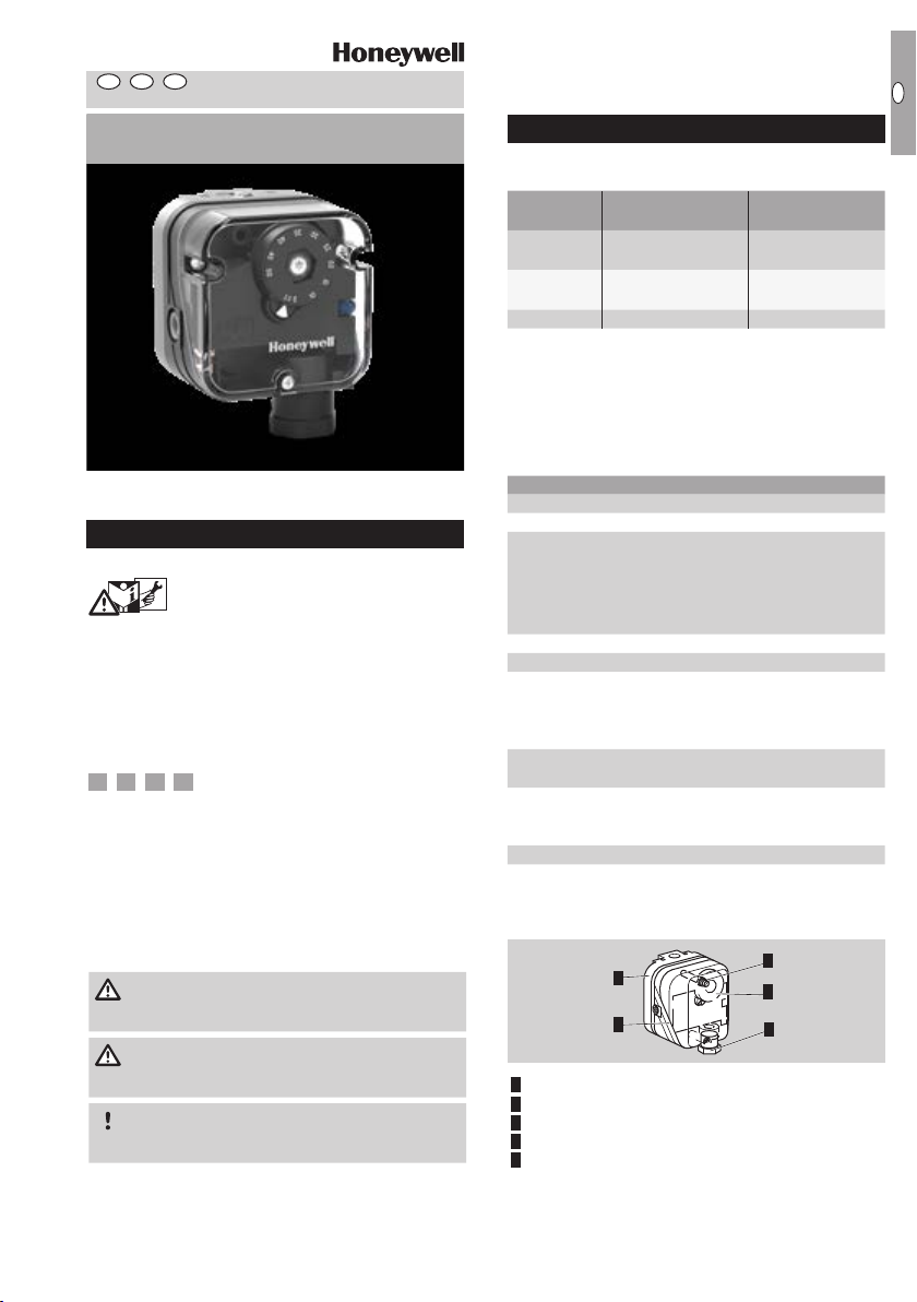
Part designations
1 Upper housing section with cover
2 Lower housing section
3 Hand wheel
4 ½" NPT conduit coupling
5 Manual reset
(DG..NT and DG..HT only)
Positive
pressure
Gas, air, flue gas,
biogas
Gas, air, flue gas,
biogas
, O2, air –
3
Negative
pressure
Air, flue gas
Air, flue gas
Switches with falling pressure
Locks off with rising pressure
Locks off with falling pressure
Switches with rising and falling pressure;
for NH
, O2 (without approval)
3
Electrical connection
via screw terminals
via screw terminals, IP65
4-pin plug, with socket, IP65
1x ¼" NPT connection
2x ¼" NPT connections
Red/green pilot LED for 24 V DC/AC
Blue pilot lamp for 120 V AC
2
1
5
3
4
USA-1
Page 2
CAN
MEX
D
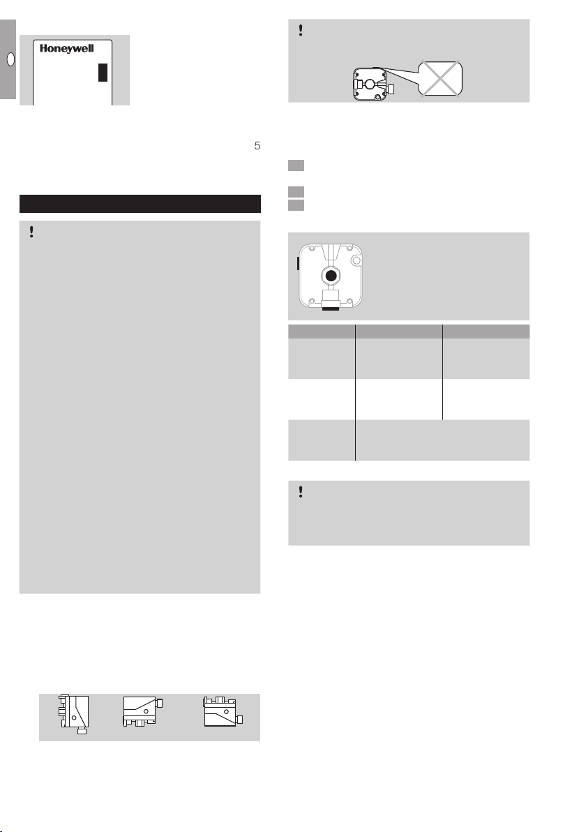
Type label
4
USA
Approval and type: see
DG T
type label.
CAUTION
If port 4 is at the top, IP65 will not be satisfied.
IP 65
For detailed information on the adjusting range, mean
switching differential, max. inlet pressure, lock-off,
medium and switching properties, see page 5
(Technical data) and the table on page 3 (Ad-
justment).
Installation
CAUTION
Please observe the following to ensure that the
DG..T is not damaged during installation and op
eration:
– Continuous operation with gases containing
more than 0.1%-by-vol. H2S or ozone concentrations exceeding 200µg/m3 accelerate
the ageing of elastomer materials and reduce
the service life.
– Use approved sealing material only.
– Dropping the device can cause permanent dam-
age. In this event, replace the entire device and
associated modules before use.
– Check max. ambient temperature – see
page5 (Technical data).
– When using silicone tubes, only use silicone
tubes which have been sufficiently cured.
– Vapours containing silicone can adversely affect
the functioning of electrical contacts.
– Condensation or vapours containing silicone
must not be allowed to get into the housing.
At subzero temperatures, malfunctions/failures
due to icing can occur.
– When installing outdoors, place the DG..T in
a roofed area and protect from direct sunlight
(even IP65 version).
– Avoid strong impact on the unit.
▷ Installation position as required, preferably with
vertical diaphragm. Then the switching point p
corresponds to the scale value SK set on the
hand wheel. In other installation positions, the
switching pointpS will change and no longer
correspond to the scale valueSK set on the
hand wheel. Check the switching point.
▷ The DG..T must not be in contact with masonry.
Minimum clearance 1" (25 mm).
▷ Ensure that there is sufficient installation space.
▷ Ensure unobstructed view of the hand wheel.
1 Disconnect the system from the electrical power
supply.
2 Shut off the gas supply.
3 Ensure that the pipeline is clean.
Ports
1 or 2 for
-
4
1
2 *
positive pressure (¼" NPT)
4 for
negative pressure (
Connect Free
Positive
pressure
1 or 2* 4
DG..T
Negative
pressure
4 1 or 2*
DG..T
Differential
pressure
DG..T
1 or 2* for higher absolute pressure.
4 for lower absolute pressure.
* Port 2 only on DG..T..2 with 2x ¼” NPT connections..
CAUTION
Port 4 connects the upper diaphragm chamber
with the micro switch. Do not connect port4 to
pipes carrying gas.
▷ The pressure switches are supplied with an inte-
grated vent limiter. In the event of a diaphragm
tear, the vent limiter limits the escape of gas
to less than 1.0 CFH of natural gas at 2.8psi
S
(DG..6T) or 7 psi (DG..10T – DG..500T). If necessary, port4 (1/8" NPT) can be used to connect
the venting line.
▷ A filter pad at port4 protects the electrical contacts
in the DG..T from dirt particles in the surrounding
air or in the medium.
▷ Filter pad for port4, see PartDetective.
1
/8" NPT)
ps = SK
ps =SK + 0,08 "WC ps = SK - 0,08 "WC
USA-2
Page 3

CAN
MEX
D
3 42
NO
NO
2
NC
1
COM
3
COM
3
NC
1
NO
2
Wiring
CAUTION
To ensure that the DG..T is not damaged during op-
eration, note the switching capacity, see page5
(Technical data).
▷ In the case of low switching capacities, such as
24V, 8mA, for example, we recommend using
an RCmodule (22 Ω, 1μF) in air containing
silicone or oil.
1 Disconnect the system from the electrical power
supply.
5
½" NPT Conduit:
ø 0.4" (10 mm)
2
NO
NC
1
3
COM
2
NO
1
NC
3
COM
½" NPT
▷
DG..FT, DG..NT: the NO-to-COM connection
is interrupted if the pressure drops (contacts 3
and 2 open).
DG..T, DG..HT: the NC-to-COM connection is
interrupted if the pressure rises (contacts 3 and
1 open).
Adjustment
▷
The switching point is adjustable via hand wheel.
1 Disconnect the system from the electrical power
supply.
2 Detach the housing cover.
▷
Tightening torques, see Technical Information
bulletin DG at www.docuthek.com.
3 Connect an ohmmeter.
NO
NC
COM
2
3
1
2
NC
1
3
COM
6 Apply pressure. In doing so, monitor the ohm-
Pressure switches without manual reset
(DG..T, DG..FT, DG..ST)
Pressure switches with manual reset
(DG..HT, DG..NT)
1)
* Adjusting tolerance = ±15% of the scale value.
** Difference between switching pressure and pos-
0
0.4" = 0.4"WC
(1 cm = 1 mbar)
meter and the pressure gauge.
Type
DG 6T
DG 10T
DG 50T
DG 150T
DG 500T
Adjusting
range*
"WC
(mbar)
0.2 – 2.4
(0.5 – 6)
0.4 – 4
(1 – 10)
1 – 20
(2.5 – 50)
12 – 60
(30 – 150)
40 – 200
(100 – 500)
Mean
switching
differential
at min.
and max.
setting
"WC
(mbar)
0.08 – 0.12
(0.2 – 0.3)
0.1 – 0.16
(0.25 – 0.4)
0.4 – 0.8
(1 – 2)
1.2 – 2
(3 – 5)
3.2 – 6.8
(8 – 17)
Max. inlet
pressure p
psi (mbar)
No
venting
line
2.4 psi
(165)
7 psi
(480)
max.
With
venting
line
8.5 psi
(600)
Max. inlet
pressure p
psi (mbar)
No
venting
line
7 psi
(480)
max.
With
venting
line
8.5 psi
(600)
Type
DG 10T
DG 50T
DG 150T
DG 500T
Adjusting
range*
"WC
(mbar)
0.4 – 4
(1 – 10)
1 – 20
(2.5 – 50)
12 – 60
(30 – 150)
40 – 200
(100 – 500)
Reset
pressure**
"WC
(mbar)
0.16 – 0.4
(0.4 – 1)
0.4 – 0.8
(1 – 2)
0.8 – 4.8
(2 – 12)
2 – 7.2
(5 – 18)
Connect the venting line to port 4. Connections,
see page 2 (Installation).
sible reset.
▷ If the DG..T does not trip at the desired switch-
ing point, correct the adjusting range using the
hand wheel. Relieve the pressure and repeat
the process.
USA
1)
1)
4 Set the switching point using the hand wheel.
5 Connect a pressure gauge.
USA-3
Page 4

CAN
MEX
D
Pressure switches with manual
1
reset
USA
▷
DG..NT locks off if the pressure drops to the
value set using the hand wheel.
▷
DG..HT locks off if the pressure rises to the value
set using the hand wheel.
1 Reset the pressure switch using the manual reset.
▷ Requirement for reset:
DG..NT: the pressure must have risen at least
to the set switching point plus the pressure differential between the switching pressure and
possible lock-off.
DG..HT: the pressure must have dropped at least
to the set switching point minus the pressure
differential between the switching pressure and
possible lock-off.
▷ For details of the pressure differential between
the switching pressure and possible reset, see
table on page3 (Adjustment).
Accessories
LED set, red/green
2
+
NO
2
3 COM
1 NC
NO
3
1
2
NC
4
3
COM
Tightness test
1 Shut off the downstream gas pipeline close to
the valve.
2 Open the valve and the gas supply.
▷ Check all used ports for tightness.
3 4
N
2
13 psi
max. 29 psi
< 15 min
Maintenance
In order to ensure smooth operation, check the tightness and function of the DG..T every year, or every
six months if operated with biogas
.
–
N
24 V DC, I = 16 mA; 24 V AC, I = 8 mA,
Order No.: 74921089.
110 to 230 V AC,
Order No.: 74923275.
USA-4
Page 5

CAN
MEX
D
Pilot lamp set, blue
1
2
COM
N
NO
NO
2
3
L1
3
2
1
NC
L1
3
COM
1
NC
N
NO
NC
NO
NO
1
2
NC
1
2
NC
4
3
COM
N
3
COM
N
110/120 V AC, I = 1.2 mA,
Order No.: 74916121.
Further information about accessories can be found
in Technical Information bulletin DG (identical to
DG..T)– www.docuthek.com
Technical data
Gas type: natural gas, town gas, LPG (gaseous),
flue gas, biogas (max. 0.1%-by-vol. H
Max. inlet pressure p
see page 3 (Adjustment).
= withstand pressure,
max.
Max. test pressure for testing the entire system: temporarily (<15minutes) 29psi (2bar).
Switching capacity:
DG..T
U I (
max. 240 V AC max. 5 A max. 0.5 A
cos φ = 1)
DG..TG* < 30 V AC/DC max. 0.1 A max. 0.05 A
*
With gold contacts
Maximum medium and ambient temperatures:
-40 to +140°F (-40 to +60°C).
Long-term use in the upper ambient temperature
range accelerates the ageing of the elastomer materials and reduces the service life (please contact
manufacturer).
The set switching point may palpably change in me-
dia and ambient temperatures below -22°F (-30°C).
Storage temperature: -4 to +104°F
(-20 to +40°C).
Diaphragm pressure switch, silicone-free.
Diaphragm: NBR.
Housing: glass fibre reinforced PBT plastic with
low gas release.
Lower housing section: AlSi 12.
Enclosure: IP65. Safety class: 1.
Cable diameter: AWG24 to AWG13
(0.02 to 0.07" (0.5 to 1.8mm)).
Line entrance: ½" NPT conduit.
Electrical connection type: screw terminals.
Max. tightening torque, see Technical Information
bulletin DG.
Safety information, see Safety manual DG (identical to DG..T)– www.docuthek.com.
Weight: 9.5 to 11.3 oz (270 to 320 g).
Dimensions
S) and air.
2
I (
cos φ = 0.6)
USA
2.76"
(70 mm)
0.43"
(11 mm)
3"
(76 mm)
1/2" NPT
USA-5
Page 6

CAN
MEX
D
Logistics
Transport
USA
Protect the unit from external forces (blows, shocks,
vibration). On receipt of the product, check that the
delivery is complete, see page1 (Part designations). Report any transport damage immediately.
Storage
Store the product in a dry and clean place.
Storage temperature: see page5 (Technical data).
Packaging
The packaging material is to be disposed of in
accordance with local regulations.
Disposal
Components are to be disposed of separately in
accordance with local regulations.
Certification
Directive on the restriction of the use of
hazardous substances (RoHS) in China
Scan of the Disclosure Table China RoHS2– see
certificates at www.docuthek.com
FM approved
Factory Mutual Research Class: 3510 Flow and pressure safety switches.
Designed for applications pursuant to NFPA 85 and
NFPA 86.
UL listed
UL 353 Limit control.
Underwriters Laboratories
Contact
If you have any technical questions, please contact
your local branch office/agent. The addresses are
available on the Internet or from ElsterGmbH.
We reserve the right to make technical modifications
in the interests of progress.
Strotheweg 1, D-49504 Lotte (Büren)
Elster GmbH
Tel. +49 541 1214-0
Fax +49 541 1214-370
hts.lotte@honeywell.com, www.kromschroeder.com
USA-6
 Loading...