

Page 1
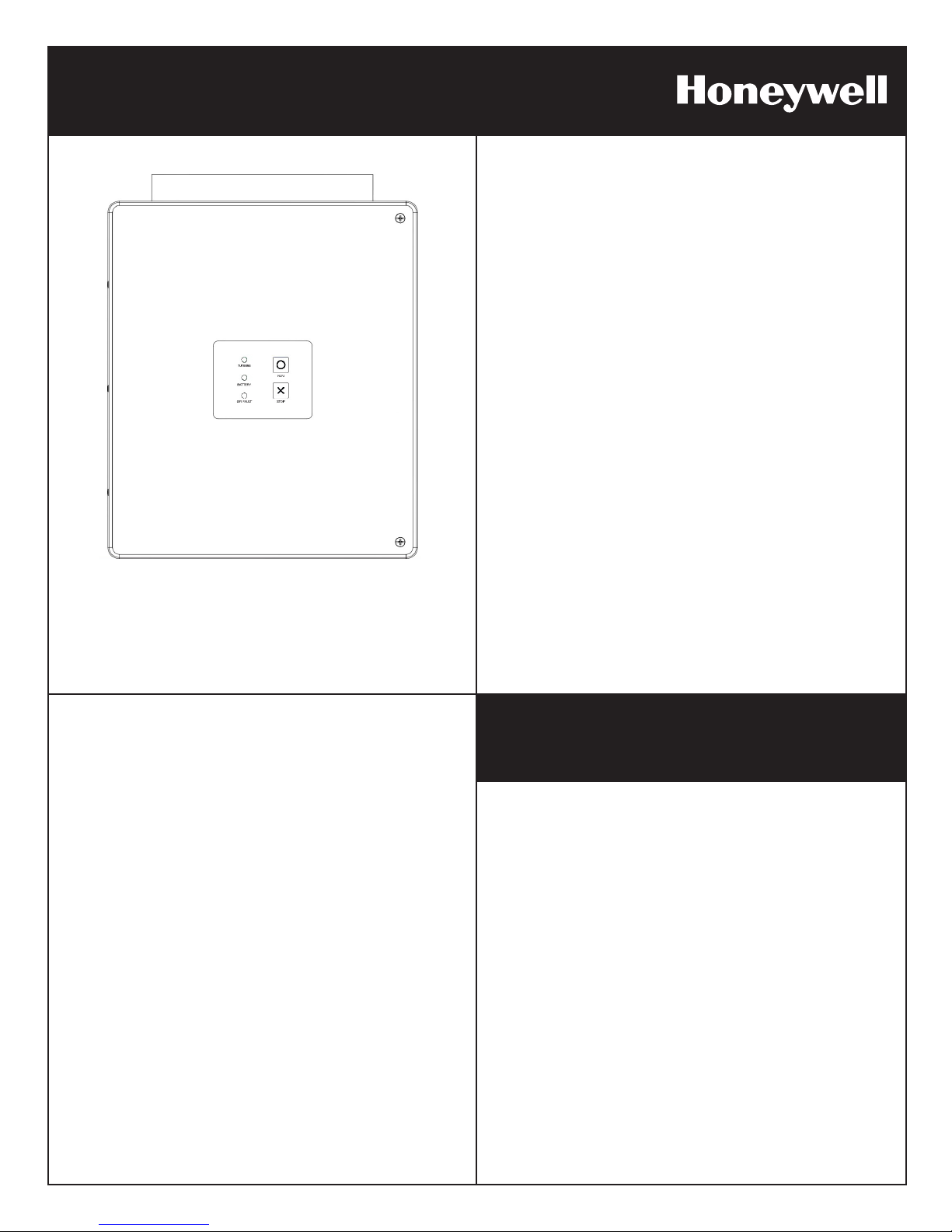
DC CHARGE CONTROLLER
for Honeywell Wind Turbine Model WT6500
Quick Start:
DC CHARGE CONTROLLER
Model #DCCC6500
48VDC
This manual is intended for the use of a licensed contractor. If you are a licensed
and insured contractor who would like to become a WindTronics Authorized
Installer, please download the application from our website www.windtronics.com.
Page 2

2
Safety Instructions
Important Safety Instructions
1. This Quick Start contains important instructions for the Honeywell Wind Turbine
installation and maintenance. Please save it.
2. Read the entire Quick Start prior to installation and follow all warnings and
cautions included in the Quick Start and/or attached to the Honeywell Wind
Turbine.
3. Improper installation, adjustment, alteration, service maintenance, or use can
cause re, electrical shock, or other conditions which may cause death, personal
injury or property damage.
4. Choose a very calm, nearly no wind, day for the installation.
5. Follow the installation procedures contained within this Quick Start and all safety
codes. Follow your National Electric Code and your local building zoning codes.
Quick Start
6. Only WindTronics Authorized Installers or other licensed contractors should move
and lift the Honeywell Wind Turbine. The turbine should only be moved using
standard hoists and hydraulic lifts such as a crane or bucket truck.
7. Appropriate protective personal equipment such as hard hat, work gloves, safety
glasses, and closed-toe work shoes should be worn when installing the Honeywell
Wind Turbine.
8. Only WindTronics Authorized Installers or other licensed contractors can perform
the following installation and maintenance functions on this Honeywell Wind
Turbine:
• Open and work on the DC Charge Controller
• Open and work on the DCCC junction box at the turbine
• Apply any torque to any of the turbine’s fasteners
9. The installation directions include recommendations of a variety of options. These
must be approved and certied by your local Professional Engineer (PE). The
installer must acquire all the necessary permits from the local authorities prior to
installation.
The Honeywell Wind Turbine is manufactured by WindTronics. Please contact
WindTronics at:
621 Sprucewood Avenue
Windsor, Ontario N9C 0B3
Canada
Tel: 877-946-3898
Manufacturer reserves the right, without notice or liability, to change design and
specications at any time.
Quick Start: DC Charge Controller for Honeywell Wind Turbine WT6500 - Rev 1.0 - 28Sep11
Page 3

Quick Start 3
Site Survey
Refer to the Site Survey Guide.
Evaluation and Installation List
Permits
Permit#_________________________ Date_____________
Permit#_________________________ Date_____________
Permit#_________________________ Date_____________
Permit#_________________________ Date_____________
Site evaluation
Distance from turbine to DC Charge Controller (max 200 ft (60m))__________
Height to center of turbine______________________________
Draw all obstructions on site map
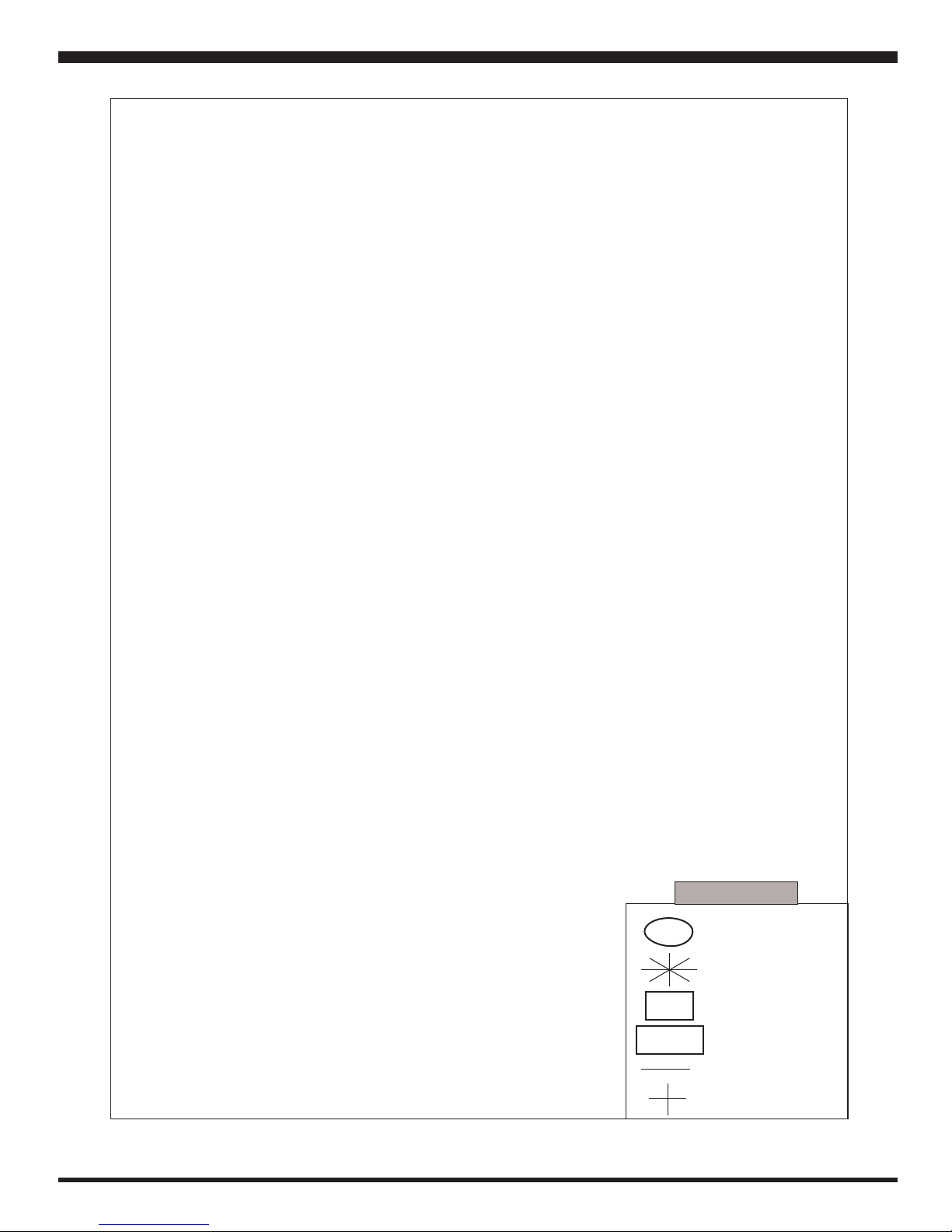
Draw site map (view from above - use space on page 5 for your drawing)
Prevailing wind direction
Location of:
Obstacles
Turbine
DC Charge Controller
Battery enclosure (max 6 ft. (1.8 m) from DC Charge Controller)
Mounting Hardware (Choose one or have your local PE design a custom mount -
see Honeywell Wind Turbine WT6500 Owner’s Manual for more details)
Pole: Height____________ material_______________ with Pole Top Mount (refer
to pages 7-8)
Flat roof: QUADPOD Mount and Ballast (refer to page 9)
Pitched roof: QUADPOD Mount and ROOFBOX Mount (refer to page 10)
Accessories (Supplied by Installer)
Quick Start: DC Charge Controller for Honeywell Wind Turbine WT6500 - Rev 1.0 - 28Sep11
Batteries: FOUR-12V, 100Ah, deep cycle batteries - Type may be AGM or marine-
grade ooded
Battery enclosure
(1) 30 Amp fuse (refer to page 14)
(1) 15 Amp fused disconnect (refer to page 14)
(1) Battery switch (refer to page 14)
Page 4

4
Connection:
Quick Start
(2) ¾” Conduit
(1) 1” Conduit
Battery terminal lugs
CAT5E or CAT6 stranded cable
(1) #4 THWN - 2 red
(4) #4 THWN - 2 black
(1) #4 THWN - 2 green
(1) #6 THWN - 2 green
(3) #10 THWN - 2 black
(1) #10 THWN - 2 red
Unpacking (Refer to instructions in package)
DC Charge Controller: Serial #___________________
Quick Start Manual
Turbine crate:
Turbine: Serial #____________________
(2) Deectors and mounting hardware
DCCC junction box with dump load
Anemometer
Owner’s Manual
QA Inspection Sheet
Unpacking instructions
A run of conduit shall contain not more
than four quarter bends or a combination of bends totaling 360 degrees
between pull points. Tubing shall not
be threaded, and ttings shall be listed
for use with EMT and shall be securely
fastened to the tubing.
Mount and Level Turbine – Refer to lift point on page 12
Connect – Refer to pages 13-14 for wiring diagrams
Commissioning – Refer to page 15
Status LED’s Operation Legend – Refer to page 16
Quick Start: DC Charge Controller for Honeywell Wind Turbine WT6500 - Rev 1.0 - 28Sep11
Page 5
Quick Start 5
Quick Start: DC Charge Controller for Honeywell Wind Turbine WT6500 - Rev 1.0 - 28Sep11
T
BB
DCCC
N
LEGEND
Turbine
Tree
Battery Box
DC Charge Controller
Prevailing Wind
Compass
Page 6
6
Mounting Options
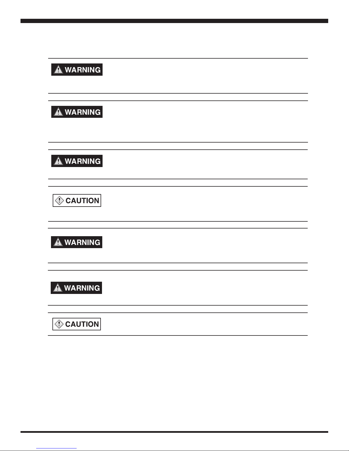
PERSONAL INJURY AND PROPERTY DAMAGE HAZARD
Do not install the Honeywell Wind Turbine in a location that is accessible to
children or pets. Failure to follow this warning may result in death, personal
injury or property damage.
PERSONAL INJURY AND PROPERTY DAMAGE HAZARD
The Honeywell Wind Turbine must be mounted by WindTronics Authorized
Installers or other licensed contractors only, with the use of all appropriate
hardware. Failure to follow this warning may result in death, personal injury
or property damage.
Failure to follow proper installation practices for any of the mounting options
could result in death, serious injury and/or property damage.
Quick Start
WHEN MOUNTING ON OR OVER A COMBUSTIBLE SURFACE, A FOOT
PLATE OF AT LEAST 1.43 mm GALVANIZED OR 1.6 mm UNCOATED
STEEL EXTENDED AT LEAST 150 mm BEYOND THE EQUIPMENT ON
ALL SIDES MUST BE INSTALLED.
Power shall be disconnected from the equipment before the DCCC junction box enclosure is opened and the enclosure shall be closed before the
power is restored. Failure to do so may result in death, serious injury and/or
property damage.
If any maintenance is to be done on the turbine, the turbine must be put in
STOP mode, the turbine switch on the DCCC junction box must be in the
“Turbine Off” position and the wheel must be tie wrapped to prevent turning.
Failure to do so may result in death, serious injury and/or property damage.
Use of WindTronics’ products for other than their intended purpose may
void warranty.
Whichever mounting option is chosen should be approved by a local Professional Engineer (PE). All of
the options listed have been rated by our Professional Engineer and certied for WindTronics. Please
refer to the following designs and their included specications.
Quick Start: DC Charge Controller for Honeywell Wind Turbine WT6500 - Rev 1.0 - 28Sep11
Page 7

Quick Start 7
Pole Mount
Figure 1 Pole Mount
Quick Start: DC Charge Controller for Honeywell Wind Turbine WT6500 - Rev 1.0 - 28Sep11
Page 8

8
Instructions for Pole Top Mount Assembly
Step 1:
• Position Leg Weldment
#WTM001 to bottom of
#WTM002 Coupler Weldment.
• Bolt together using fastener #’s:
70210, 70714, 71021, 71071 as
shown.
• Repeat pattern in three additional
locations.
Step 2:
• Position Mounting Bracket
#WTM003 to top of #WTM002
Coupler Weldment.
• Bolt together using fastener #’s:
70210, 70714, 71021, 71071 as
shown.
Quick Start
Note:
Be sure both pole and pole coupler are installed level. Failure to
install them level will impact turbine
performance and may impact
warranty coverage.
Be sure the inner surface of the
Mounting Leg Weldment is ush
against the pole prior to bolting the
fasteners. Choose the bolt hole in
the base of the Pole Mount Turbine
Coupler Weldment that aligns with the
slot in the Mounting Leg Weldment.
Pole Top Mount Assembly #WTMASSY001
Item No. Part No. Description Qty
1 WTM001 Mounting Leg Weldment 4
2 WTM002 Pole Mount Turbine Coupler Weldment 1
3 WTM003 Pole Mount Junction Box Mounting Bracket 1
5 Fastenal #70210 Hex Cap Screw, 1/2-13 x 1.75” lg Full Thread 18-8 S/S 9
6 Fastenal #71071 Flat Washer - 1/2”, Medium Split, 18-8 Stainless Steel 9
7 Fastenal #71021 Flat Washer - 1/2”, Small O.D., 18-8 Stainless Steel 9
8 Fastenal #70714 Hex Nut - 1/2-13 - 18-8 Stainless Steel 9
Figure 2 Pole Top Mount
See Pole Top Mount Assembly and Installation Instructions for complete details.
Quick Start: DC Charge Controller for Honeywell Wind Turbine WT6500 - Rev 1.0 - 28Sep11
Page 9

Quick Start 9
Ballast Mount
Figure 3 Ballast Mount
Quick Start: DC Charge Controller for Honeywell Wind Turbine WT6500 - Rev 1.0 - 28Sep11
Page 10

10
ROOFBOX with Extended QUADPOD Mount
Quick Start
Figure 4 ROOFBOX with Extended QUADPOD Mount
Quick Start: DC Charge Controller for Honeywell Wind Turbine WT6500 - Rev 1.0 - 28Sep11
Page 11

Quick Start 11
DCCC Junction Box
Purpose:
The DC Charge Controller junction box is the interface between the turbine and the
DC Charge Controller which includes the dump load, turbine ON/OFF switch and
anemometer. The DC Charge Controller uses the dump load to put the turbine in STOP
mode when there is a fault, a user has pressed the STOP key, or when the generator
voltage exceeds 165VDC. When the voltage decreases, the brake is released. The
turbine ON/OFF switch will put the turbine in a hard STOP mode whether or not the
dump load is connected. It also disconnects the turbine from the DC Charge Controller.
Mounting:
The junction box comes hard wired to the turbine. It should be mounted to ensure the
anemometer will be able to function through all seasons (i.e. will not be covered with
snow in the winter). The junction box can be mounted through two pre-drilled holes
tapped for 5/16”-18 bolts in the black mounting bars on the back of the junction box.
The QUADPOD Mount has pre-drilled holes for mounting of the junction box. Mounting
hardware is supplied by the Installer.
Figure 5 DCCC Junction Box
Quick Start: DC Charge Controller for Honeywell Wind Turbine WT6500 - Rev 1.0 - 28Sep11
Page 12

12
Lift Point
Quick Start
Only WindTronics Authorized Installers or other licensed contractors should move and
lift the Honeywell Wind Turbine. The turbine should only be moved using standard
hoists and hydraulic lifts such as a crane or bucket truck. The recommended lift point
is shown in gure 6.
Wiring
Figure 6 Proper Turbine Lift Point
ELECTRIC SHOCK HAZARD
Disconnect turbine and battery circuits before wiring. Turn off all power
before wiring. Failure to follow safety warning could result in serious injury
and/or death.
PROFESSIONAL INSTALLATION: REQUIRED
Installations must meet all local electrical codes. Installations for the equipment should
only be performed by WindTronics Authorized Installers or other licensed contractors.
The wiring connections between a mounted Honeywell Wind Turbine, battery box and
DC Charge Controller are relatively simple. Figure 8 (page 14) details and species
the wire gauges required in this installation. It is strongly recommended that a licensed
electrician performs all the electrical connections. All electrical systems must be
grounded in accordance to your National Electric Code and local standards.
Quick Start: DC Charge Controller for Honeywell Wind Turbine WT6500 - Rev 1.0 - 28Sep11
Page 13

Quick Start 13
Illustration of Turbine System Connections
Figure 7 System Connection
Quick Start: DC Charge Controller for Honeywell Wind Turbine WT6500 - Rev 1.0 - 28Sep11
Page 14

14
Quick Start
Junction Box
Figure 8 Electrical Wiring Diagram
Quick Start: DC Charge Controller for Honeywell Wind Turbine WT6500 - Rev 1.0 - 28Sep11
Page 15

Quick Start 15
Commissioning
EXPLOSION OR FIRE HAZARD
Entering battery information incorrectly may result in
explosion or re.
1. To congure the DC Charge Controller to a 48VDC system (refer to gure 9) set
switch S1 to “On”.
2. Set switch S2 to “On”.
3. Set switch S3 to either “On” if using AGM batteries, or “Off” is using ooded batteries
(refer to gure 9).
4. Turn on the following switches in the following sequence:
• Battery switch
• DC Charge Controller ON/OFF switch
• 15 Amp fused disconnect
• DCCC junction box ON/OFF switch
5. Verify turbine LED on DC Charge Controller is green.
Figure 9 Battery Conguration Switches
Quick Start: DC Charge Controller for Honeywell Wind Turbine WT6500 - Rev 1.0 - 28Sep11
Page 16

16
Status LED’s Operation Legend
TURBINE LED
1. NO LED
• Turbine is sleeping or DC Charge Controller is off
2. GREEN
• Turbine is running
3. RED
• Turbine is stopped
4. ONE RED BLINK
• No Wind Speed – Turbine Voltage > 40VDC and Wind Speed = 0 MPH for
1 minute
5. TWO RED BLINKS
• Turbine over current – Turbine current > 9 Amps
Quick Start
BATTERY LED
6. THREE RED BLINKS
• No turbine fault – Turbine Voltage < 5VDC and Wind Speed > 10
MPH for 1 minute
7. FOUR RED BLINKS
• Turbine over voltage – Turbine Voltage > 170VDC
1. GREEN
• Batteries are charged (when battery voltage stays at 55V for a 48V
battery system).
2. ONE RED BLINK
• Low battery fault – Batteries are lower than 45V (for a 48V battery
system).
3. TWO RED BLINKS
• High battery fault – Batteries are higher than 58V (for a 48 Volts battery
system).
4. THREE RED BLINKS
• Charge over temp – Enclosure > 65°C or Heat Sink > 140°C
5. FOUR RED BLINKS
• Charge over current – Charge current > 24 Amps
GFI LED
1. RED
• Indicates GFI Fault
Quick Start: DC Charge Controller for Honeywell Wind Turbine WT6500 - Rev 1.0 - 28Sep11
Page 17

Quick Start 17
Spare Parts
Part Description Part Number #/Turbine Supplier
Finned Dump Load Enclosure Assembly RDLASSY6500 1 WindTronics
Anemometer DI7911 1 WindTronics
Replacement Honeywell Turbine RWT6500 1 WindTronics
Replacement DC Charge Controller 48VDC DCCC6500 1 WindTronics
Pole Top Mount MPT6500 1 WindTronics
QUADPOD Mount MQP6500 1 WindTronics
QUADPOD Mount - Ballast (for at roof) MQP6500B 1 WindTronics
QUADPOD Mount - Feet (for pitched roof) MQP6500F 4 WindTronics
Quick Start: DC Charge Controller for Honeywell Wind Turbine WT6500 - Rev 1.0 - 28Sep11
Page 18

The Honeywell trademark is used under license from
Honeywell International Inc. Honeywell International Inc.
makes no representation or warranties with respect to this
product.
WindTronics
621 Sprucewood Avenue
Windsor, Ontario N9C 0B3
Canada
Tel: 877-946-3898
www.windtronics.com
WT6500-QSDCCC-Rev1.0-28Sep11
 Loading...