

Page 1
UDC3000
L
Versa-Pro
Universal Digital Controller
Overview
The UDC3000 Universal Digital
Controller is Honeywell’s general
purpose microprocessor-based,
stand alone digital controller. It
combines the highest degree of
functionality and operating simplicity offered in a 1/4 DIN size.
The bright dual displays with multilanguage prompts make the
operator interface easy to read,
understand, and operate.
Programmed sequences of displays assure quick and accurate
entry of all configurable parameters. Simple keystrokes let you
select input and range configuration, set the operating parameters
that meet your process control
needs now, and change them later
to meet new ones.
Features
Dual Displays -
cent alphanumeric displays and
indicators with dedicated PV
display.
Deviation Bargraph -
indication or up to ± 10% deviation
display.
Easy Configuration -
language prompts, in programmed
sequence, provide guidance during
configuration. Individual, reliable
tactile keys provide positive
operator feedback. There are no
internal jumpers to set.
Universal Isolated Input -
Input 1 accepts 10 thermocouple
types, RTDs, Radiamatic RHs, mA,
mV or voltage inputs through
keyboard configuration. It is isolated
from Input 2 and all other circuits.
(See Table 1.)
Thermocouple Failsafe -
Configurable upscale or downscale
burnout and failsafe output level.
Decimal Point Location -
Configurable for none, one, or two
places.
Vacuum fluores-
“On Control”
Multi-
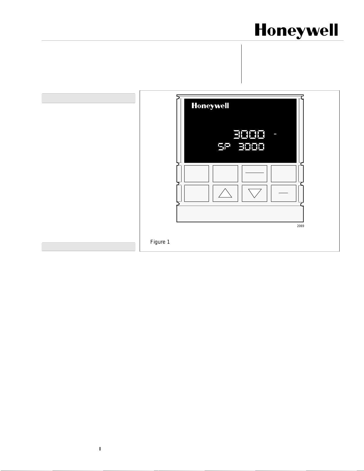
Figure 1 - UDC3000 Versa-Pro Controller
Accutune II
truly plug and play tuning algorithm,
which will, at the touch of a button
or through a digital input, accurately
identify and tune any process
including those with deadtime and
integrating processes. This speedsup and simplifies startup plus allows
retuning at any setpoint. Also
included is the original Accutune SP
Adaptive tuning that can
automatically retune whenever a SP
step change is implemented.
Fuzzy Logic -
uses fuzzy logic to suppress
process variable overshoot due to
SP changes or externally induced
process disturbance. It operates
independently from Accutune
tuning. It does not change the PID
constants, but temporarily modifies
the internal controller response to
suppress overshoot. This allows
more aggressive tuning to co-exist
with smooth PV response. It can be
enabled or disabled depending on
the application or the control
criteria.
TM
ALM
DI
RSP
OUT
FUNCTION
SET UP
- Provides a new,
This new feature
F C
1 2
1 2
1 2
SP 3000
LOWER
DISPLAY
L
51-52-03-07
Page 1 of 12
Specification
MAN
3000
MANUAL
AUTO
Manual/Automatic Modes -
Bumpless, balanceless transfer
between control modes.
Two Local Setpoints -
configured to provide two local
setpoints, keyboard or optional
remote switch selectable.
Universal Switching Power -
Operates on any line voltage from
90 to 264 Vac 50/60 Hz without
jumpers. 24V ac/dc instrument
power available as an option.
Limit Control -
relay which is activated whenever
the PV goes above or below a
preset setpoint value. An alarm
indicator will light when the output is
activated. Reset is through a key on
the front of the controller or an
external switch.
Setpoint Rate -
ramp rate to be applied to any local
setpoint change. A separate
upscale or downscale rate is
configurable. A single setpoint ramp
is also available as an alternative.
%
SETPOINT
SELECT
RUN
HOLD
22069
Can be
provides a latching
Lets you define a
2/97
Industrial Automation and Control, 110 Virginia Drive, Fort Washington, PA 19034
Printed in U.S.A. ■ Copyright 1997 Honeywell Inc.
Page 2

51-52-03-07
Page 2
Features, continued
CE
Mark-
73/23/EEC, Low Voltage Directive
and 89/336/EEC, the EMC Directive
Moisture Resistant Front Panel -
Capable of meeting NEMA 3 and
IEC529 IP65 (i.e. hosedown)
requirements.
Timer -
vides a configurable time period of
0 to 99 hours, 59 minutes. Alarm 1
is dedicated to be active at the end
of the timeout period. Timer “start”
is selectable as either the
RUN/HOLD key or Alarm 2. The
optional Digital Input can also be
configured to start the Timer in
addition to either the keyboard or
Alarm 2. The Timer status shown in
the lower display is selectable as
either time remaining or elapsed
time.
Two Sets of Tuning Constants -
Two sets of PID parameters can be
configured for each loop and
automatically selected.
Heat/Cool Capability -
split range control with independent
PID tuning constants - one for
heating, one for cooling, plus mixed
output forms.
Alarm Selection -
two relays to activate external
equipment when preset high/low
setpoints are reached. There is an
indicator for each alarm.
Setpoint Ramp -
programmable setpoint ramp of up
to 255 minutes duration which is
repeatable and activated by the
Run/Hold key.
Output Rate Limiter -
output rate may be configured for
both the upscale and downscale
output directions.
Data Security -
board security protect tuning,
configuration, and calibration data,
accessed by a configurable 4-digit
code. Nonvolatile EEPROM
memory assures data integrity
during loss of power.
Quality/Support -
covered by a 2-year warranty and
backed up by a toll-free phone
number for technical assistance.
Conformity with
This standard feature pro-
Provides
None, one, or
Provides single
A maximum
Five levels of key-
The UDC3000 is
Optional Features (Fig. 4)
Second Input - Isolated high level
input available for remote setpoint
signal, PV signal via digital inputs,
or motor slidewire input. (Table 1)
Auxiliary Output* - This isolated
Auxiliary Output can be scaled from
4-20 mA for 0 to 100% for any
range. It can be configured to
represent Input 1, Input 2, PV,
active Setpoint, Local SP1,
Deviation, or the Control Output.
Communications* - Provides a link
between the UDC3000 and a
Honeywell supplied interface device
capable of communicating via
RS232 (DMCS), or direct
communication via the RS422/485
communications option to a host
computer.
Approval Body Options - FM
approval, CSA certification and UL
Recognition are available options.
UL Recognition applies to
regulatory use only.
2 Digital Inputs - Allows remote
dry contact closure to select one of
the following for each digital input:
• Manual control mode
• Local setpoint 1
• Local setpoint 2
• Direct controller action
• Reset of Limit Controller
• Hold SP Ramp/Programming
• Select PID set 2
• PV = Input 2
• External program reset
• Disable PID integral action
• To Run - SP Ramp/Program
• To Automatic output value
• Manual mode, failsafe output
• Disable keyboard
• Start Timer
• To Auto/Manual Station
• ToTune
Also allows the following selections
to be combined with the above
selections:
• Select PID set 2
• Direct controller action
• Local setpoint 2
• Disable adaptive tune
Transmitter Power - Provides up
to 30 volts to power a 2 wire
transmitter (requires use of alarm 2
open collector output selection or
auxiliary output.)
* AuxOut and communications are mutually
exclusive (only one may be specified).
Optional Features continued
Auto/Manual Station Plus Backup
Control - You can use a single
UDC3000 to act as both an
Auto/Manual Station PLUS a backup PID Controller, should the
primary loop controller fail. Since
the PID control is sometimes
implemented in the PLC, this
feature provides a very costeffective way to insure the process
does not have to shutdown or
remain in manual mode if the PLC
should fail. Switching from the
Auto/Manual Station to the back-up
control mode is accomplished using
the Digital Input option.
Setpoint Ramp/Soak
Programming - Enables you to
program and store 6 Ramp and 6
Soak segments for setpoint
programming. Run or Hold of
program is keyboard or remote
switch selectable.
Physical Description
The controller is housed in a 5.8
inch deep, black metal case with a
dark gray elastomer bezel, that can
be panel mounted in a 1/4 DIN
cutout, (see Figure 5.) The plug-in
chassis allows easy access to the
controller board and its various
option boards. All power, input, and
output wiring are connected to
screw terminals on the rear panel,
(see Fig 6.) Blue and tan elastomer
bezels are optionally available.
Inputs
Each analog input is sampled 3
times a second, amplified and
then converted to a digital signal
which is isolated and passed to
the microprocessor. The primary
input can be one of various
Thermocouple, Radiamatic, or
Linear actuations, (see Table 1.)
A second input provides a remote
setpoint function and accepts a 4
to 20 mA or 1 to 5 Vdc range that
can be characterized. All ranges
are keyboard selectable. External
cold junction compensation is
provided. You can select upscale
downscale, or failsafe sensor
break protection. A configurable
digital filter of 0 to 120 seconds for
each Input provides input signal
smoothing, if required.
Page 3

51-52-03-07
Page 3
Output Types
The following output types are
available per the model selection
guide:
• Current output
• Electromechanical relays
• Solid state relays
• Open collector output
• Solid state relay (10 amp)
externally mounted (optional)
• Auxiliary current output
(optional)
Output Algorithms
The UDC3000 is available with one
or more of the following output
algorithms:
Time Proportional - provides OnOff or Time Proportional (Relay)
output.
Current Proportional - supplies
proportional direct current output for
final control elements which require
a 4-20 mA signal.
Position Proportional - positions a
reversible motor with a feedback
slidewire in proportion to the output
of the control algorithm. Requires 2
output relays.
Time Proportional Duplex -
depending on which control
algorithm you select, this duplex
output algorithm can provide OnOff Duplex, Time Proportional
Duplex, or 3 Position Step Control.
The time proportional duplex output
provides independent PID tuning
constants and two time proportional
outputs; one for heat zone above
the 50% output, and one for cool
zone below 50% output.
Current Proportional Duplex -
similar to current proportional but
provides a second set of tuning
parameters and a split range
current output or a second current
output via the Auxiliary output
option, for the heat and cool zones.
Output Algorithms, cont
Current/Relay Duplex (Relay =
Heat) - a variation of Duplex with
Current active for 0 to 50% output
(Tuning Set 2) and Relay active 50
to 100% output (Tuning Set 1).
Current/Relay Duplex (Relay =
Cool) - a variation of Duplex with
Current active for 50 to 100%
output and Relay is active for 0 to
50% output.
“Universal” Output Model Flexibility of the Output Algorithms
allows the Current Output Model
with 2 Alarms (DC300K-E) to be
also configured for time simplex,
time duplex, or three position step
control plus, of course, the original
capability of current simplex and
current/time duplex control. A Relay
Output Model with Auxiliary Output
can also be configured for these
output algorithms.
Control Algorithms
Depending on the output algorithms
specified, the controller can be
configured for the following control
algorithms:
• On-Off
• PID-A
• PID-B
• PD with Manual Reset
• Three Position Step Control
The Three Position Step
Control algorithm allows the
control of a valve (or other actuator), with an electric motor
driven by two controller output
relays; one to move the motor
upscale, the other downscale
without a feedback slidewire
linked to the motor shaft.
Accutune does not apply to this
algorithm. Features of this
algorithm are:
1. The controller can use all
three modes of control
(PID) instead of PI only.
2. Three Position Step is an
automatic backup mode to
Position Proportional
Control if the feedback
slidewire signal should fail.
Configuration
You decide how the controller is to
interact with the process by selecting, through simple keystrokes, the
functions you want.
Multi-language prompts guide the
operator step-by-step through the
configuration process assuring
quick and accurate entry of all
configurable parameters. There are
no internal jumpers, all configuration is via the keyboard. Five
languages are available via
configuration; English, French,
German, Spanish and Italian.
Control Modes
Manual or Automatic control with
bumpless, balanceless transfer
between modes is a standard
feature. In the manual mode, the
operator directly controls the
controller output level. In the
automatic mode, the controller will
operate from a local setpoint, or a
remote setpoint provided at the
second input or via
communications.
Alarms
Alarm output terminals are located
at the rear terminal panel. One or
two electromechanical alarm relays
are available to activate external
equipment when preset alarm set
points are reached. Each of the two
alarms can be set to monitor two
independent set points. Each alarm
setpoint can be either high or low
alarm. The alarm type can be
selected to be either of the inputs,
the Process Variable, Deviation,
Output, Shed from communications
or to alarm on manual mode. It can
also be used as an On or Off event
at the beginning or end of a
Ramp/Soak segment. The alarm
hysteresis is configurable from 0 to
100% of range.
Page 4
51-52-03-07
L
Page 4
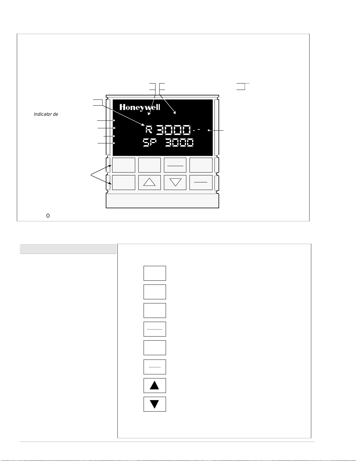
R - Run SP Ramp/Program
H - Hold SP Ramp/Program
Indicator definition when lit
ALM - Alarm conditions exist
DI - Digital Input active
RSP - Remote SP or SP2 active
OUT - Control Relay 1 or 2 on
Keys - See below
Upper Display - Six Characters
• Normal Operation - four digits dedicated to display the process variable
• Configuration Mode - displays parameter value or selection
Lower Display - eight characters
• Normal Operation - displays operating parameters and values
• Configuration Mode - displays function groups and parameters
Indicator definition when lit
F - °Fahrenheit being used
C - °Centigrade being used
ALM
1 2
DI
1 2
RSP
OUT
1 2
SP 3000
FUNCTION
SET UP
LOWER
DISPLAY
F C
R
MAN - controller in manual mode
A - controller in automatic mode
MAN
3000
MANUAL
AUTO
%
SETPOINT
SELECT
RUN
HOLD
Deviation Bargraph
• Center bar indicates PV is
within ± 1% of setpoint.
• Next bar will light if PV is
between ±1% but less than
±2% in deviation.
• If PV is equal to or greater than
±10% deviation, the center bar
plus all ten deviation bars will
light.
MAN and A off —
communications
option active
Figure 2 - Operator Interface
Operator Interface (Fig. 2)
Indicators - They provide alarm,
control mode, and temperature units
indication. There is also indication of
when Remote Setpoint is active, the
status of the control relays, and
whether a setpoint program is in Run
or Hold mode.
A 21-segment bargraph displays
deviation to ±10% of span and an
“On-Control” indicator.
Displays - A 4-digit upper display
is dedicated to the process variable during normal operation with
alternate 6-character information
displayed when in the configure
mode.
During normal operation, the lower
display shows key-selected operating parameters such as Output,
Setpoints, Inputs, Deviation, active
Tuning Parameter Set, Timer Status,
or minutes remaining in a setpoint
ramp (4 digits). It also provides
guidance, through prompts, for the
operator during controller
configuration
(8-characters).
SET UP
FUNCTION
LOWER
DISPLAY
MANUAL
AUTO
SETPOINT
SELECT
RUN
HOLD
Figure 3 - Key Functions
Sequentially displays Set Up groups and allows
Function key to display individual functions.
Selects functions within each Set Up group.
Selects an operating parameter to be shown in
the lower display.
Selects Manual or Automatic control mode.
(may be disabled via configuration)
Alternately selects Local setpoint 1 and Remote
setpoint or between two local setpoints.
(may be disabled via configuration)
Initiates or holds the single setpoint ramp
or Ramp/Soak program.
(may be disabled via configuration)
Increases the setpoint, output, or
configuration values displayed.
Decreases the setpoint, output, or
configuration values displayed.
22816
22071
Page 5

Design
CE Conformity (Europe)
Product Classification:
Enclosure Rating:
Installation Category
(Overvoltage Category):
Pollution Degree:
EMC Classification:
Method of EMC Assessment:
Declaration of Conformity:
Accuracy
51-52-03-07
Page 5
Specifications
This product is in conformity with the protection requirements of the following
European Council Directives: 73/23/EEC, the Low Voltage Directive, and
89/336/EEC, the EMC Directive. Conformity of this product with any other “CE
Mark” Directive(s) shall not be assumed.
Class I: Permanently Connected, Panel Mounted Industrial Control Equipment
with protective earthing (grounding). (EN61010-1)
Panel Mounted Equipment, IP 00, this controller must be panel mounted.
Terminals must be enclosed within the panel. Front panel IP 65 (IEC 529).
Category II: Energy-consuming equipment supplied from the fixed installation.
Local level appliances, and Industrial Control Equipment. (EN 61010-1)
Pollution Degree 2: Normally non-conductive pollution with occasional
conductivity caused by condensation. (Ref. IEC 664-1)
Group 1, Class A, ISM Equipment (EN 55011, emissions), Industrial Equipment
(EN 50082-2, immunity)
Technical File (TF)
51309303-000.
± 0.20% of span typical (± 1 digit for display)
15 bit resolution typical
Temperature Stability
Input Signal Failure Protection
Input Impedance
Stray Rejection
± 0.01% of Full Scale / ˚C change
Thermocouple Inputs:
Burnout Current:
Failsafe Output Level:
4-20 Milliampere Input:
0-10 Volt Input:
All Other:
10 Megohms
Upscale or downscale burnout
0.13 microamps
Configurable 0-100%
250 Ohms
200K Ohms
Common Mode
AC (50 or 60 Hz): 120 dB (with maximum source impedance of 100 Ohms) or ± 1
LSB ((least significant bit) whichever is greater.
Normal Mode
AC (50 or 60 Hz): 60 dB (with 100% span peak-to-peak maximum)
Alarm Output One SPDT electromechanical relay.
A second alarm is available using the second control relay. This is not available
with Relay Duplex, Position Proportional, or Three Position Step control.
Up to four setpoints are independently set as high or low alarm, two for each
relay. Setpoint can be on either Input, Process Variable, Deviation,
Communication Shed, or Output. A single adjustable hysteresis of 0.0 to 100.0%
is provided. The controller can also be set to alarm on shed from
communications. The alarm can also be set as an on or off event at the
beginning of a setpoint ramp/soak segment.
Alarm Relay Contacts Rating
Resistive Load:
5 ampere at 120 Vac or 30 Vdc, 2.5A at 240 Vac.
Page 6

51-52-03-07
Page 6
Design (continued)
Specifications (continued)
Controller Output Types
Current Output (Isolated)
Range can be set anywhere between 0 to 21 mA, and as direct or reverse
action.
Resolution:
Accuracy:
Temperature Stability:
Load Resistance:
11 bits for 0 to 21 mA
0.5% full scale
0.1% F.S. / ˚C
0 to 1000 ohms
Electromechanical Relays (One or Two)
SPDT contacts. Both Normally Open and Normally Closed contacts are brought
out to the rear terminals.
Internally socketed
Resistive Load:
Inductive Load:
Motor:
1/6 H.P.
5 amps @ 120 Vac, 2.5A at 240 Vac or 30 Vdc
50 VA @ 120 Vac or 240 Vac
Solid State Relays (One or Two)
SPST solid state contacts consisting of a triac N.O. output.
Internally socketed
Resistive Load:
Inductive Load:
1.0 amp @ 25 ˚C and 120 or 240 Vac
0.5 amp @ 55 ˚C and 120 or 240 Vac
50 VA @ 120 Vac or 240 Vac
Open Collector Outputs (One or Two)
Maximum Sink Current:
Overload Protection:
Internally powered @ 30 Vdc
Opto-isolated from all other circuits except current output, but not from each
other.
Socketed jumper assembly replaces relay.
20 mA
100 mA
Solid State Relays (10 amps)
One or two externally mounted triac N.O. outputs for use with open collector
outputs.
Resistive Load:
Inductive Load:
Motor Rating:
15 amps @ 25 ˚C and 120 or 240 Vac
10 amps @ 55 ˚C and 120 or 240 Vac
50 VA @ 120 Vac or 240 Vac
1 HP @ 25 ˚C
0.75 HP @ 55 ˚C
Controller Output Algorithms On-Off or Time Proportional
One relay or open collector output. Control action can be set for direct or reverse.
Time Proportional Relay Resolution:
On-Off Duplex, Three Position Step Control, or Time Proportional Duplex
Two relays or open collector outputs. Control action can be set for direct or
reverse.
Time Proportional Relay Resolution:
Current Proportional
A single 4-20 mA current output signal which can be configured for direct or
reverse action.
Current Proportional Duplex
A single split current output for both heat and cool (4-12 cool, 12-20 heat) or a
combination of current proportional output (Heat = 50 to 100% of range) and
auxiliary current output (Cool = 0 to 50% of range). Both are 4-20 mA signals
which can be set for direct or reverse action.
Position Proportional
Two SPDT electromechanical or solid state relays operate motor having a 100
ohm to 1000 ohm feedback slidewire.
Current/Time Duplex
Variation of time proportional duplex for Heat/Cool applications. Time proportional
output (heat or cool) is a relay. Current proportional output (Heat or Cool) is a 4-20
mA signal that can be fed into a negative or positive grounded load of 0 to 1000
ohms and is operational over 50% of range or the entire range.
Sampling Rate Inputs sampled 3 times a second
3.3 msec
3.3 msec
Page 7

Design (continued)
51-52-03-07
Page 7
Specifications (continued)
Auxiliary Linear Output (Optional)
(Isolated)
Communications Interface (Optional)
DMCS
RS422/485
Digital Inputs (Optional) +15 Vdc source for external dry contacts or isolated solid state contacts. The
Input Filter
21 mA dc maximum into a negative or positive grounded load or non-grounded
load of 0 to 1000 ohms.
Output range can be set anywhere between 0 to 21 mA, and as direct or reverse
action. It can be configured to represent either Input, PV, Setpoint, Deviation, or
Control output. The range of the auxiliary output, as a function of the selected
variable, can be scaled. This output can be used as a second current output for
current duplex outputs.
Resolution:
Accuracy:
Temperature Stability:
Baud Rate:
Length of Link:
Link Characteristics:
Baud Rate:
Parity:
Odd or Even
Length of Link:
Link Characteristics:
drops maximum
Digital Input option detects the state of external contacts for either of the two inputs.
On contact closure the controller will respond according to how each digital input is
configured. Opening contact causes return to previous state.
Software
seconds available on both analog inputs.
12 bits over 0 to 21 mA
0.2% of full scale
0.01% F.S. / ˚C
19200 baud
4000 ft maximum
Two wire, multi-drop proprietary protocol, 31 drops maximum
300, 600, 1200, 2400, 4800, or 19,200 baud
4000 ft maximum
Two wire or four wire, multi-drop RS422 ASCII protocol, 15
: Single pole lowpass section with selectable time constants, off to 120
Digital Displays Vacuum fluorescent, alphanumeric.
Indicators Alarm Relay Status (ALM 1 or 2)
Bargraph 21 segment, vertical Deviation bargraph
Modes of Operation Manual
Dimensions See Figure 5.
Mounting Panel-mounted, 5.82 inch depth
Wiring Connections Screw terminals on the rear of the case. (See Figure 6.)
Power Consumption 18 VA maximum
Power Inrush Current
A six-character upper display dedicated to the process variable (4 digits).
Alternate information displayed during configuration mode.
A eight-character lower display primarily shows key selected operating parameters
(4 digits). Also provides guidance during controller configuration.
Control Mode (A or MAN)
Temperature Units (F or C)
Remote Set Point or SP2 Active (RSP)
Control Relay Status (OUT 1 or 2)
Digital Input Status (DI 1 and 2)
Center bar lit when “on” control
Deviation to ± 10% of PV span in 1% increments
Automatic with local setpoint
Automatic with remote setpoint (2-input units only)
10A Max. for 4 ms (under operating conditions)
CAUTION
sufficient power is supplied. Otherwise, the controllers may not start up normally
due to voltage drop from the inrush current.
When applying power to more than one UDC3000, make sure that
Weight 1.3 kg (3 lbs.)
Page 8

51-52-03-07
Page 8
Specifications (continued)
Environmental and Operating Conditions
Parameter Reference Rated Operative Limits Transportation and storage
Ambient
Temperature
Relative Humidity 10 to 55* 10 to 90* 5 to 90* 5 to 95*
Vibration
Frequency (Hz)
Acceleration (g)
Mechanical Shock
Acceleration (g)
Duration (ms))
Voltage (Vdc) +24 ± 1 20 to 27 20 to 27 - -
Voltage (Vac)
90 to 264Vac
(CSA models rated to 250V max.)
25 ± 3˚C
77 ± 5˚F
0
0
0
0
120 ± 1
240 ± 2
15 to 55
58 to 131
0 to 70
0.1
1
30
90 to 264
˚C
˚F
0 to 55˚C
32 to 131
0 to 200
0.5
5
30
90 to 264
˚F
-40 to 66˚C
-40 to 151
0 to 200
0.5
20
30
- -
- -
˚F
24Vac
Frequency (Hz)
(For Vac)
* The maximum rating only applies up to 40˚C (104˚F). For higher temperatures, the RH specification is derated to maintain constant moisture content.
24 ± 1
50 ± 0.2
60 ± 0.2
20 to 27
49 to 51
59 to 61
20 to 27
48 to 52
58 to 62
- -
- -
- -
Table 1 - Input Actuations
Range
PV Input ˚F ˚C
Thermocouples
B*
E*
E (low)
J
J (low)
K
K (low)
NiNiMoly (NNM)
NiNiMoly (NNM low))
NIC (Nicrosil Nisil)
R
S
T
T (low)
W5W26
W5W26 (low)
RTD
(IEC) ALPHA = 0.00385
100 Ohms
100 Ohms (low)
500 Ohms
Radiamatic RH 1400 to 3400 760 to 1871
Linear**
Milliamps
Millivolts
Volts
0 to 3300
-454 to 1832
-200 to 1100
0 to 1600
20 to 770
0 to 2400
-20 to 1000
32 to 2500
32 to 1260
0 to 2372
0 to 3100
0 to 3100
-300 to 700
-200 to 500
0 to 4200
0 to 2240
-300 to 1200
0 to 300
-300 to 1200
4 to 20 mA
0 to 10 mV
10 to 50 mV
1to5V
0 to 10V
-18 to 1815
-270 to 1000
-129 to 593
-18 to 871
-7 to 410
-18 to 1316
-29 to 538
0 to 1371
0 to 682
-18 to 1300
-18 to 1704
-18 to 1704
-184 to 371
-129 to 260
-18 to 2316
-18 to 1227
-184 to 649
-18 to 149
-184 to 649
Optional 2nd Input
Milliamps
Volts
Slidewire for Position
Proportioning
* May require Field calibration to achieve rated accuracy below 1000 ˚F for type B and below -200 ˚F for type E thermocouple.
** Not available on FM approved Limit models.
4 to 20 mA
1to5V
100 to 1000Ω
Page 9

Data
Isolation
(Functional)
Surge Withstand
Capability (SWC)
Radio Frequency
Interference (RFI)
51-52-03-07
Page 9
General Reference Data
AC Power :
1900Vdc for 2 seconds per Annex K of EN61010-1.
Analog Inputs and Outputs:
Digital Input and Digital Output:
Relay Contacts:
345 Vdc for 2 seconds.
Immunity:
input and relay contact outputs: 2.5 kV, Common Mode and Differential Mode. All other circuits: 1.0 kV,
Common Mode and Differential Mode.
Immunity
meter from the controller.
is electrically isolated from all other inputs and outputs to withstand a HIPOT potential of
are isolated from each other and all other circuits at 850Vdc for 2 seconds.
are isolated from all other circuits at 850Vdc for 2 seconds.
with a working of 115/230 Vac, isolated from each other and all other circuits at
ANSI/IEEE C37.90.1, Surge Withstand Capability (SWC) (Formerly IEEE 472) Mains power
: No effect on performance from a 5 W walkie-talkie operated at 27, 151 or 450 MHz, one
Model Number Interpretation
Table 1 Table 2 Table 3 Table 4 Table 5Key Number
DC3 00
0
Output #1
C = Current 4 – 20mA without Alarms
K = Current 4 – 20mA with Alarm 1
E = Relay, Electromechanical – 5AMP with Alarm 1
A = Relay, Solid State AC – 1AMP with Alarm 1
T = Open Collector Output – 20mA with 1 Alarm
Output #2 or Alarm #2
O = None
E = Relay, Electromechanical – 5AMP (SPDT)
A = Relay, Solid State AC – 1AMP (SPST)
T = Open Collector Output – 20mA
External Interface
O – – = None
1 – – = RS422/485
2 – – = Auxiliary Output
4 – – = DMCS
Software Options
– O – = None
– A – = Accutune
– B – = Setpoint Program and Accutune
Digital Inputs
– – O = None
– – 3 = Digital Inputs (2)
Options
0 – – – =
1 – – – =
B – – – =
T – – – =
C – – – =
D – – – =
– 0– – =
– A – – =
– F – – =
– – 0– =
– – T – =
– – – 0 =
– – – D =
Optional Input
– 0 =
– 1 =
– 2 =
PV Input
1 – =
T/C, RTD, mV, 1–5V
2 – =
T/C, RTD, mV, 1–5V,
4–20mA
3 – =
T/C, RTD, mV, 1–5V,
4–20mA,0–10V
90-264Vac Power
24Vac/dc Power
Blue Bezel with
90-264Vac Power
Tan Bezel with
90-264 Vac Power
Blue Bezel with
24Vac/dc Power
Tan Bezel with
24Vac/dc Power
None
Approvals CSA,FM,UL
Approvals - FM,
CSA
None
Customer I.D. Tag
None
DIN Cutout
Adapter
None
4–20mA or 1–5V
Slidewire Input for Position
Proportional or 3 Position
Step with motor position
indication
22603
Figure 4 - Model Number Interpretation
Page 10

51-52-03-07
L
L
L
Page 10
Dimensions
24
.945
96
3.780
Max Panel
Thickness
ALM
ALM
AL
DI
PV
DI
M
RSP
RSP
OUT%1 2
OUT
FUNCTION
SET UP
1 2
1 2
1
1 2 3 4
1 2
1
2
2
1 2
1 2
96
3.780
F C
F
C
LOWER
DISPLAY
F C MAN
MAN
M
A
N
MANUAL
AUTO
%
%
SETPOINT
SELECT
RUN
HOLD
10
.394
Max (2)
92
3.622
+0.008
-0.0
+0.03
-0.0
Panel Cutout
2.4
.093
92
3.622
+0.008
-0.0
+0.03
-0.0
with optional
rear cover
21.6
.850
Figure 5 - UDC3000 Versa-Pro Controller dimensions - not to scale
147.3
5.82
90.7
3.57
22073
Page 11

Wiring Diagram
51-52-03-07
Page 11
L1/H
Instrument Power
L2/N
22
23
24
25
26
27
NOTE:
The product manual should be consulted for specific details and precautions regarding wiring.
Figure 6 - External Wiring Diagram
0
IN 2
IN 1
UDC 3000 EXTERNAL WIRING
10
11
12
13
14
15
16
17
DI 1
DI 2
SHIELD
RX+/TX+
RX-/TX-
TX+ or AUX+
TX- or AUX-
1
2
3
4
5
6
7
8
9
!
CTL 1
4-20 MA
CTL 2
ALM 2
ALM 1
22840
Page 12

51-52-03-07
Page 12
Ordering Information
For the complete ordering information, request Model Selection Guide:
51-51-16-32 for UDC3000 Universal Digital Controller or .
.
Honeywell offers a full Iine of Sensors, Transmitters, and Final Control Devices for use with the UDC3000
Universal Digital Controller. These devices include:
Thermocouples, RTDs
Pressure Transmitters,
Flow Transmitters,
Liquid Level Transmitters.
Valve, Actuators, and Electric Motors.
Specifications are subject to change without notice.
Distributor :
For more information, contact your nearest Honeywell Response Center listed below.
Industrial Automation and Control
Honeywell Inc.
In the U.S.A.:
In Europe:
In Japan:
In Asia:
In the Mediterranean:
Honeywell Pacific Division:
In Canada:
In Latin America:
Honeywell Industrial Automation and Control, 16404 North Black Canyon HWY., Phoenix, AZ 85023, (800) 343-0228
Honeywell S.A., 80084 Amiens Cedex 2, (33) 22.54.56.56
Honeywell Control System Ltd., Honeywell House, Bracknell, UK-RG 12 1 EB, (44) 1344 826000
Yamatake-Honeywell Co. Ltd., Nagai Int’l Bldg., 2 - 12 - 19 Shibuya-Ku, Tokyo 150 Japan, 81-3-3486-2051
Honeywell Asia Pacific Inc., Room 3213-3225, Sun Hung kai Centre, No. 30 Harbor Road, Wanchai, Hong Kong, (852) 829-8298
The Honeywell centre, 155 Gordon Baker Road., Ontario M2H 3N7, 1-800-461-0013
Africa and Middle East Region, Honeywell SpA, Via Vittor Pisani 13, 20124 Milano, Italy (39-2) 67731
Honeywell Pty Ltd., 5 Thomas Holt Drive, North Ryde Sydney, NSW Australia 2113, (61-2) 353 7000
Honeywell Inc.,14505 Commerce Way, Suite 500, Miami Lakes, Florida 33016-1556, (305) 364-2300
 Loading...