

Page 1
10/06
30-10-10-06-EN
Page 1 of 16
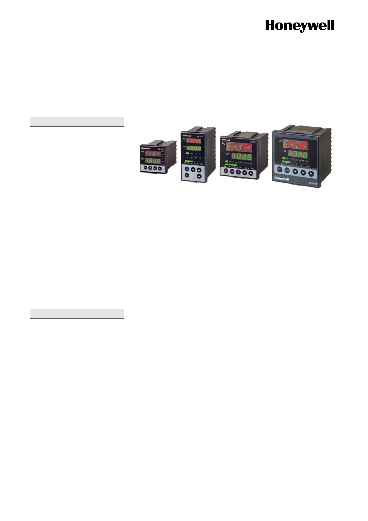
DC1010/DC1020/DC1030/DC1040
DIGITAL CONTROLLERS Specification
Overview
The DC1000 Series are microprocessorbased controllers designed with a high
degree of functionality and reliability at a
competitive price. The controllers are
available in different formats: 48x48
(1/16 DIN), 48x96 (1/8 DIN), 72x72
(3/16 DIN), 96x96 (1/4 DIN). This
controller series is ideal for the control of
temperature, humidity, pressure, flow etc.
in a variety of applications including:
z Plastic Processing
z Package Machinery
z Painting and coating
z Semiconductor packaging / Testing
z Dryers
Features
z Easy to Configure
Different configuration level s provide easy
access to parameters.
z Various Control Algorithm
Several different algorithms are available
as follows:
- PID or ON/OFF Control
- Heat/Cool Control with 2 PID sets
- Motor Position Control
(without slidewire feedback)
z Auto-Tuning Capability
Advanced auto-tuning function calculates
the optimized PID values for your specific
control system.
z Dual Display and Bar graph
Two large 4 digits display PV, SP and
configuration parameters. One 10 LED
bar-graph displays the control output
(MV), and up to 8 LEDs display the status
of the different outputs (Control, Alarm,
…) and also provide indication of the
Auto/Manual and programmer states.
z Setpoint Programming
Two programs are available with a
maximum of 8 segments. The 2 programs
can be linked together and perform as a
single 16 segment program.
z Extended Alarm Capability
Up to three different alarm outputs are
available per instrument and 17 kinds of
event modes can be assigned to each of
alarm output.
z Communications
RS232 or RS485 (with ASC II & Modbus
RTU Protocol) is optionally available with
a maximum communication speed of
38400 bps.
z IP65 Front Face Protection
IP65 rated front face permits use in
applications where it may be subjected to
moisture, dust conditions.
z Remote Setpoint Capability
The setpoint can be defined from a
remote PLC or other controller.
z Manual & Automatic Modes
The control mode can be switched
between Automatic and manual by
clicking A/M key. (The A/M key is
available with DC1020, DC1030 and
DC1040)
z Global Approvals – CE & cUL
All models are CE certified as a standard,
and UL approved version for all models
are available optionally.
z Parameter Lock
A 4-digit security code prevents any
unauthorized changes of parameters or
configurations. Parameters can be hidden
to user to prevent any mis-conf iguration
of the unit.
Page 2
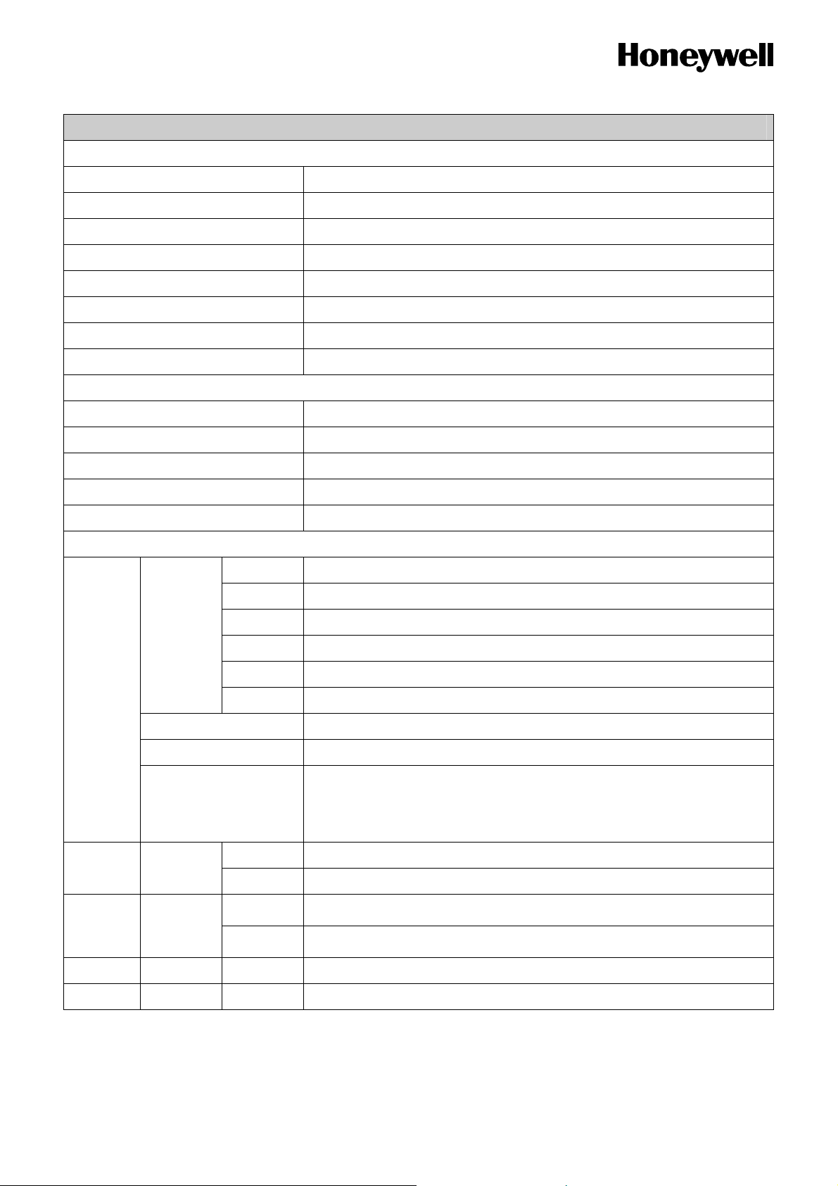
Specifications
General
Rated power supply voltage 100 to 240V AC 50/60Hz, 8VA max.
15 to 50V DC, 10VA max.
Insulation Resistance
Over 10㏁ under DC500V megger between input terminal and
case(ground).
Over 10㏁ under DC500V megger between output terminal and
case(ground).
Withstand voltage 1000V AC 50/60Hz for 1min across input terminal and case(ground)
1500V AC 50/60Hz for 1min across output terminal and case(ground)
Standard
Conditions
Ambient Temp.
Ambient Humi. 60 ± 5% RH
23 ± 2 °C
Rated Power Supply 110V AC
Power Frequency 50 ± 1Hz or 60 ± 1HZ
Operating
Conditions
Ambient Temp.
Ambient Humi. 20 to 90%RH (non-condensing)
0 to 50°C
Rated Power Supply 100 to 240V AC
20 to 50V DC
Allowable Power
85 to 264V AC
Supply
15 to 55VDC
Power Frequency 50 ± 2Hz or 60 ± 2Hz
2
(approx. 1G), 10 to 55Hz for 10min each X, Y, Z directions
-20 to +65 °C
2
(Approx. 2G), 10 to 55Hz for 2 hours each in X, Y, Z directions
Transportatio
n and storage
conditions
Vibration Resistance 10m/s
Ambient Temp.
Ambient Humi. 10 to +95% RH (non-condensing)
Vibration Resistance 20m/s
Exterior Case and front panel : plastic
Mounting Panel-mount
Model DC1010 DC1020 DC1030 DC1040
Exterior Size (unit:
mm
inch
)
50 X 50 X 97
(1.97X1.97X 3.82)
50 X 96 X 97
(1.97X3.78X3.82)
74 X 74 X 97
(2.91X2.91X3.82)
: W X H X D
Panel Cutout (unit:
mm
inch
)
44.5 X 44.5
(1.75 X 1.75)
44.5 X 90.5
(1.75 X 3.56)
68.5 X 68.5
(2.97 X 2.97)
: W X H
Global Approvals CE, cUL
96 X 96 X 97
(3.78X3.78X3.82)
90.5 X 90.5
(3.56 X 3.56)
Interval = 20.5mm (0.807 in)
Page 3
Specifications
Input/Output
Analog
Input 1
Analog
Input 2
Number of Point 1 point (TC, RTD or Linear)
TC: K, J, R, S, B, E, T, N, W, U, PLII, L
RTD : DPt100, JPt100, JPt50
Type
Linear : 4~20mA / 1~5V / 2~10V * Note 1
0~20mA / 0~5V / 0~10V * Note 1
Refer to Table 1-1.
Range
* Temperature unit : ºC, ºF ( switchable)
Sampling cycle 250 ms
Indication
± 0.2% FS ± 1digit (for details Table1-1)
Accuracy
Cold junction
±1.0ºC (under standard conditions)
accuracy
Input bias (offset) LSPL ~ USPL
Digital Filter 0 - 200 sec (0: filter off)
Decimal Point 0000, 000.0, 00.00, 0.000
0~20mA / 0~5V / 0~10V
Type
4~20mA / 1~5V / 2~10V
Sampling Cycle 250ms
CT Input
Type
Sampling Cycle 500msec
Indication
Accuracy
Resolution 0.1A ac
Weight
Dielectric strength 2500Vac, for 1 min between terminal and case
Measure AC current of single phase
SC-80T : 0.0~80.0A
1% FS
12g
NOTE 1. When OUT1 is ON and CT input value is less than HBA set value for 5 seconds, AL1 is activated.
Otherwise, AL1 is not activated.
Page 4
Specification
Input/Output
Model DC1010 DC1020 DC1030 DC1040
Analog
Output 1
Analog
Output 2
(* Note 1)
Relay
Voltage Pulse
Linear
Relay
Voltage pulse
Linear
SPST SPDT SPST SPDT
3A, 220Vac, Resistive Load(100,000 time electrical life)
PWM(SSR drive), ON: 20 Vdc, OFF: 0 V (max. load current 20mA)
Open Time Terminal Voltage: 20 Vdc or less
Time Proportional Cycle Time: 0-150 sec
DC Current (mA) : 0~20mA, 4~20mA (load resistance 500Ω)
DC Voltage (V) : 0~5V, 0~10V, 1~5V, 2~10V (max. load current 20mA)
Accuracy ± 5% of Span
Update Cycle 500m sec
SPST SPST SPST SPST
3A, 220Vac, Resistive Load(100,000 time electrical life)
PWM(SSR drive), ON: 20 Vdc, OFF: 0 V (max. load current 20mA)
Open Time Terminal Voltage: 20 Vdc or less
Time Proportional Cycle Time: 0-150 sec
DC Current (mA) : 0~20mA, 4~20mA (load resistance 500Ω)
DC Voltage (V) : 0~5V, 0~10V, 1~5V, 2~10V (max. load current 20mA)
Accuracy ± 5% of Span
Update Cycle 500m sec
Output Direction (OUD) HEAT(Direct)/COOL(Reverse) (Selectable)
Auto/Manual operation is switchable.
Control Mode
Object SP, PV
No. of point 1 point
Transmission
Type 4-20mA, 0~20mA, 0~5V, 0~10V, 1~5V, 2~10V
Output
Accuracy +/- 0.2% of span
Update Cycle 500 ms
AL1 SPST SPDT SPST SPDT
AL2 SPST SPDT SPST SPDT
Digital Output Relay
AL3 - SPST SPST SPST
3A, 220Vac, Resistive Load(100,000 time electrical life)
*Manual output : Bumpless in normal mode
OUTL in abnormal mode
* For Heat/Cool Control Output only.
Page 5
Specification
PID Control & Auto-Tuning
Proportional Band (P1,P2) Proportional Band: 0.0 ~ 200.0%
Integral time (I1, I2) Integral time : 0 ~ 3600 sec
Derivative time (D1, D2) 0 ~ 900 sec
Auto-Tuning Value 0 ~ USPL
HYS1, HYS2 0 ~ 1000 (for ON/OFF control)
Dead Band (DB1) Not defined.
GAP1, GAP2 0 ~ 1000(for HEAT/COOL control)
Cycle Time 0 ~ 150 sec
Communication
Speed 1200, 2400, 4800, 9600, 19200, 38400 bps
Protocol ModBus RTU, ModBus ASCII
Parity check Odd / Even
Bit length 8
Communication RS232C, RS485
Events(ALARMS)
01 / 11 Deviation-High alarm (inhibit / no-inhibit)
02 / 12 Deviation-Low alarm (inhibit / no-inhibit)
Code
PV Event
SET VALUE -1999~ USPL (Absolute value, Deviation value)
Activation Hysterisis 0 ~ 1000
On Delay Time
Program Code
03 / 13 Deviation High/Low Limit alarm (inhibit / no-inhibit)
04 / 14 Deviation High/Low Limit range alarm (inhibit / no-inhibit)
05 / 15 Absolute High alarm by PV (inhibit / no-inhibit)
06 / 16 Absolute Low alarm by PV (inhibit / no-inhibit)
0 : Flicker
99M 59S : Continuance
00M 01S to 99M 58S : Time Delay
07 Segment End alarm(in progress of program)
17 Program RUN
08 System Error ON
System Code
18 System Error OFF
TIME Code 19 Delaying timer (00Hours 00Min ~ 99Hour 59Min)
HBA Code 09 Heater Break Alarm
Page 6

Specification
Program (Optional)
No. of programs 2 (Program 1 & Program 2)
No. of segments 8 segments/1 program
Program
section
Segment time
Control output
WAIT function
Repeat Repeat / Non-repeat
Program link When Program number is 0, Link program 1 and 2.
Program start
Segment time: Setting by set points(SP) and time
(Max. 99hours 59minutes)
0~100%
When OUT=0%, Program End.
Rear Wait
Time may exceed set time of the particular segment. In this case, remaining
time is set as 0 and pending; if the temperature that was measured does
not reach target value ± WAIT set point. It proceeds to the next segment
after it is confirmed that temperature reach the range of set point (target
value ± WAIT)
Setup range: ± 0 ~ 1000 by decimal point.
(1) Start from SP=0
(2) Start from PV
Power Failure Hot Start / Cold Start
TIME UNIT Hour. Minute / Minute. Second
Ramp & Soak
Slope(Ramp) Temperature : 0.0 to 99.99 / min
SOAK TIMER Max. 99 hours 59 min
POWER FAILURE It starts from PV.
Page 7

Table 1-1
Analog Input Range (Thermocouple)
Input Type Code
K1 0.0~200.0 0.0~392.0
K2 0.0 ~ 400.0 0.0~752.0
K
K3 0 ~ 600 0~1112
K4 0 ~ 800 0~1472
K5 0 ~ 1000 0~1832
K6 0 ~ 1200 0 ~ 2192
J1 0.0~200.0 0.0~392.0
J2 0.0 ~ 400.0 0.0~752.0
J
J3 0 ~ 600 0~1112
J4 0 ~ 800 0~1472
J5 0 ~ 1000 0~1832
J6 0 ~ 1200 0 ~ 2192
R1 0~1600 0~2912
R
R2 0~1769 0~3216
Temperature Range
ºC ºF
Indication
Accuracy
+/-0.2%FS
+/-0.2%FS
+/-0.2%FS
Remarks
+/-2 ºC under 100 ºC
+/-3.6 ºF under 212 ºF
TC
(Note1)
S
+/-0.2%FS
S2 0~1769 0~3216
S1 0~1600 0~2912
B1 0~1820 0~3308 +/-0.2%FS No guarantee at 0 ~ 400ºC
E
E1 0~800
E2 0~900
N1 0~1200
N
N2 0~1300
T1 -199.9~400.0
0~1472
0~1652
0~2192
0~2372
-199.9~752.0
+/-0.2%FS
+/-0.2%FS
+/-1 ºC under -100 ºC
+/-0.2%FS
T
T2 -199.9~200.0
T3 0.0~350.0
-199.9~392.0
0.0~662.0
+/-0.2%FS
+/-1.8 ºF under -148 ºF
0~2300 0~3632 W5Re/
+/-0.2%FS
W26Re
0~2320 0~4208
PL1 0~1300 0~2372
PLII
+/-0.2%FS
PL2 0~1390 0~2534
U1 -199.9~600.0
-199.9~999.9
+/-1 ºC under -100 ºC
+/-0.2%FS
U
U2 -199.9~200.0
-199.9~392.0
+/-1.8 ºF under -148 ºF
U3 0.0~400.0 0.0~752.0 +/-0.2%FS
L1 0~400 0~752
L
+/-0.2%FS
L2 0~800 0~1472
Page 8

Table 1-2
Analog Input Range (RTD)
Input Type Code
JPt100
DIN
RTD
Pt100
JPt50
Input Type
ºC ºF
JP1 -199.9~600.0 -199.9~999.9
JP2 -199.9~400.0 -199.9~752.0
JP3 -199.9~200.0 -199.9~392.0
JP4 0~200 0~392
JP5 0~400 0~752
JP6 0~600 0~1112
DP1 -199.9~600.0 -199.9~999.9
DP2 -199.9~400.0 -199.9~752.0
DP3 -199.9~200.0 -199.9~392.0
DP4 0~200 0~392
DP5 0~400 0~752
DP6 0~600 0~1112
JP.1 -199.9~600.0 -199.9~999.9
JP.2 -199.9~400.0 -199.9~752.0
JP.3 -199.9~200.0 -199.9~392.0
JP.4 0~200 0~392
Indication
Accuracy
+/-0.5 ºC under -100 ºC
+/-0.9 ºF under -148 ºF
+/-0.2%FS
+/-0.5 ºC under -100 ºC
+/-0.9 ºF under -148 ºF
+/-0.2%FS
+/-0.5 ºC under -100 ºC
+/-0.9 ºF under -148 ºF
+/-0.2%FS
Remarks
JP.5 0~400 0~752
JP.6 0~600 0~1112
Table 1-3
Analog Input Range (Linear)
Input Type Code Source Range
AN1 -10~10mV
AN2 0~10mV
Linear
AN3 0~20mV
AN4 0~50mV 0-20mA, 0-1V, 0-5V, 0-10V
AN5 10~50mV
-1999~9999 +/-0.1% of span
Indication
Remarks
Accuracy
4-20mA, 1-5V, 2-10V
Page 9

Picture 1.1
External Dimension
100%
60
20
40 80
0%
DC1030
200% 40 60 100%80
8040200% 60 100%
Page 10

(
)
A
Picture 1-2
Wiring Diagram – DC1010
N
POWER
L
AC 100 ~ 240V
50 / 60Hz
DC 15 ~ 50V
(option)
Noise
Filter
1
11
2
12
3
13
4
14
5 10
6
7
8
9
PV
Linear
ALARM
2
R
TD
7
8
9
10
7
B
8
9
B
10
A
AL1
11
T
C
7
8
9
10
AL2AL1
13
OUT2
OUTPUT
Relay
2
Volt
Linear
231
OUT1=5
11
G1
3
A,B,C,D
OUT1
Relay Volt
4
Linear
231
12
K1
13
G2
14
K2
5
A,B,C,D
OUT1=7
3
12
14
2
3
4
5
CLOSE
OPEN
COM
UX. OUT
TRS
CT INPUT
CT
COMM.
11
12
11
RS232
RD
SD
SG
COMM
COMM
RS485
11
12
13
D-
D+
11
12
13
12
Page 11

(
)
A
Picture 1-3
Wiring Diagram – DC1020
AC 100 ~ 240V
DC 15 ~ 50V
L
POWER
N
50 / 60Hz
(option)
Noise
Filter
1 11
2 12
3 13
4 14
5 15
6 16
7 17
8 18
9 19
10 20
PV
L
inear
17
18
19
20
R
TD
17
B
18
19
B
20
A
T
C
17
18
19
20
OUT2
OUT1
OUTPUT
Relay Volt
6
7
Relay Volt
8
Linear
231
A,B,C,D
Linear
NO
231
NC
9
10
COM
OUT1=7
6
7
CLOSE
A,B,C,D
LARM
AL1 AL2 AL3
NC
3
NO
4
5
COM
COM
NC
11
NO
12
13
6
7
AUX. OUT
11
TRS
12
13
8
OPEN
9
10
COM
INPU T2
14
15
16
COMM .
COMM
RS232
RD
14
SD
15
SG
16
COMM
RS485
14
D-
15
D+
16
CT INPUT
CT
14
15
Page 12

(
)
A
A
Picture 1-4
Wiring Diagram – DC1030
OUT2
OUT1
POWER
N
AC 100 ~ 240V
50 / 60Hz
DC 15 ~ 50V
(option)
OUTPUT
Relay
3
4
Relay Volt
NO
5
NC
6
7
COM
OUT1=7
3
4
CLOSE
L
Volt
231
231
Noise
Linear
A,B,C,D
Linear
A,B,C,D
Filter
OUT1=5
15
G1
17
G2
19
20
OUT1=8
15
G1
16
K1
1 15 8
2 16 9
3 17 10
4 18 11
5 19 12
6 20 13
7 21 14
PROT
PV
LARM
3
4
L
inear
11
12
13
14
COM
CT INPUT
CT
R
TD
11
B
12
13
B
14
A
UX. OUT
AL2AL1
8
NO
9
10
NC
TRS
15
16
T
C
11
12
13
14
18
19
5
OPEN
17
G2
18
6
7
COM
K2
20
PROT
21
INPUT2
Remote SP
9
10
COMM.
COMM
RS232
RD
15
SD
16
SG
17
COMM
RS485
15
D-
16
D+
17
Page 13

(
)
A
A
Picture 1-5
Wiring Diagram – DC1040
AC 100 ~ 240V
DC 15 ~ 50V
CT INPUT
POWER
50 / 60Hz
(option)
CT
L
Noise
Filter
1 31 11
2 32 12
N
3 33 13
4 34 14
5 35 15
6 36 16
7 37 17
8 38 18
14
15
9 39 19
10 40 20
COMM.
COMM
RS232
RD
31
SD
32
SG
33
UX. OUT
TRS
COMM
RS485
D-
D+
39
40
31
32
33
OUT2
OUTPUT
Relay
6
Volt
231
Linear
OUT1=6
31
RG
OUT1=5
31
G1
33
35
37
RG
TG1
TG2
33
39
40
G2
PROT
OUT1
7
Relay
8
A,B,C,D
Linear
Volt
NO
231
PV
Linear
17
18
19
20
R
TD
17
B
18
19
B
20
A
T
C
17
18
19
20
9
10
OUT1=7
6
7
CLOSE
8
OPEN
9
10
COM
NC
COM
A,B,C,D
39
40
OUT1=8
31
G1
32
K1
33
G2
34
K2
35
36
PROT
PROT
OUT1=9
31
G1
32
K1
33
G2
34
K2
35
G3
K3
36
39
40
PROT
LARM
AL1 AL2 AL3
NC
3
NO
4
5
COM
INPUT2
Remote SP
NC
NO
COM
COMM
11
12
13
COMM.
RS232
14
15
16
RD
14
SD
15
SG
16
6
7
COMM
RS485
14
D-
15
D+
16
Page 14

Model Interpretation
Page 15

Page 16

gap
Warranty / Remedy
Honeywell warrants goods of its manufacture as being free of defective materials and faulty workmanship. Contact your local
sales office for warranty information. If warranted goods are returned to Honeywell during the period of coverage, Honeywell will
repair or replace without charge those items it finds defective. The foregoing is Buyer's sole remedy and is in lieu of all other
warranties, expressed or implied, including those of merchantability and fitness for a particular purpose. Specifications may
change without notice. The information we supply is believed to be accurate and reliable as of this printing. However, we assume
no responsibility for its use.
While we provide application assistance personally, through our literature and the Honeywell web site, it is up to the customer to
determine the suitability of the product in the application.
Honeywell Process Solution
IM&C Asia Pacific
Honeywell Building
17 Changi Business Park Central 1
ore 486073
Sin
Specifications are subject to chang e without notice.
www.honeywell.com/imc
 Loading...