

Page 1
DC1010 - DC1020 - DC1030 - DC1040
PRODUCT SPECIFICATION SHEET
OVERVIEW
The DC1000 family of
microprocessor based controllers
combine a high degree of
functionality and reliability at a
very low price. Available in 4
different formats : 1/16 DIN, 1/8
DIN, 3/16 DIN, 1/4 DIN. These
controllers are ideal for regulating
temperature in a variety of
applications, including :
• Dryers.
• Semiconductor packaging /
testing.
• Plastic processing.
• Packaging machinery.
• Painting and coating.
• Climatic chambers.
The DC1000 family provides
basic control requirements, plus
advanced features such as motor
position control, phase angle
power control and Setpoint
programming.
FEATURES
Easy to configure
Two different configuration levels
provide easy access to parameters.
A 4-digit security code prevents
unauthorized changes. Parameters
can also be hidden to the user to
prevent mis-configuration of the unit.
Various Control algorithms
The DC1000 series of controllers
provide several different algorithms:
• PID or ON/OFF control.
• Heat/Cool algorithms with 2
different PID sets.
• Motor position control without
slidewire feedback.
• Single phase control, with or
without zero crossover control.
• Three phase control, with or
without zero crossover control.
Dual display and Bargraph
Two large 4 digits displays and one 10
LED bargraph display PV, SP and
configuration parameters. Up to 8 LEDs
display the status of the different Outputs
(Control, Alarm, …) and also provides
indication of the Auto/Manual and
Programmer states.
Setpoint Programming
Two programs are available, with a
maximum of 8 segments.
The 2 programs can be linked together to
form a single 16 segment program.
Extended Alarm capability
Three different alarm outputs are
available per instrument, 17 alarm modes
are configurable.
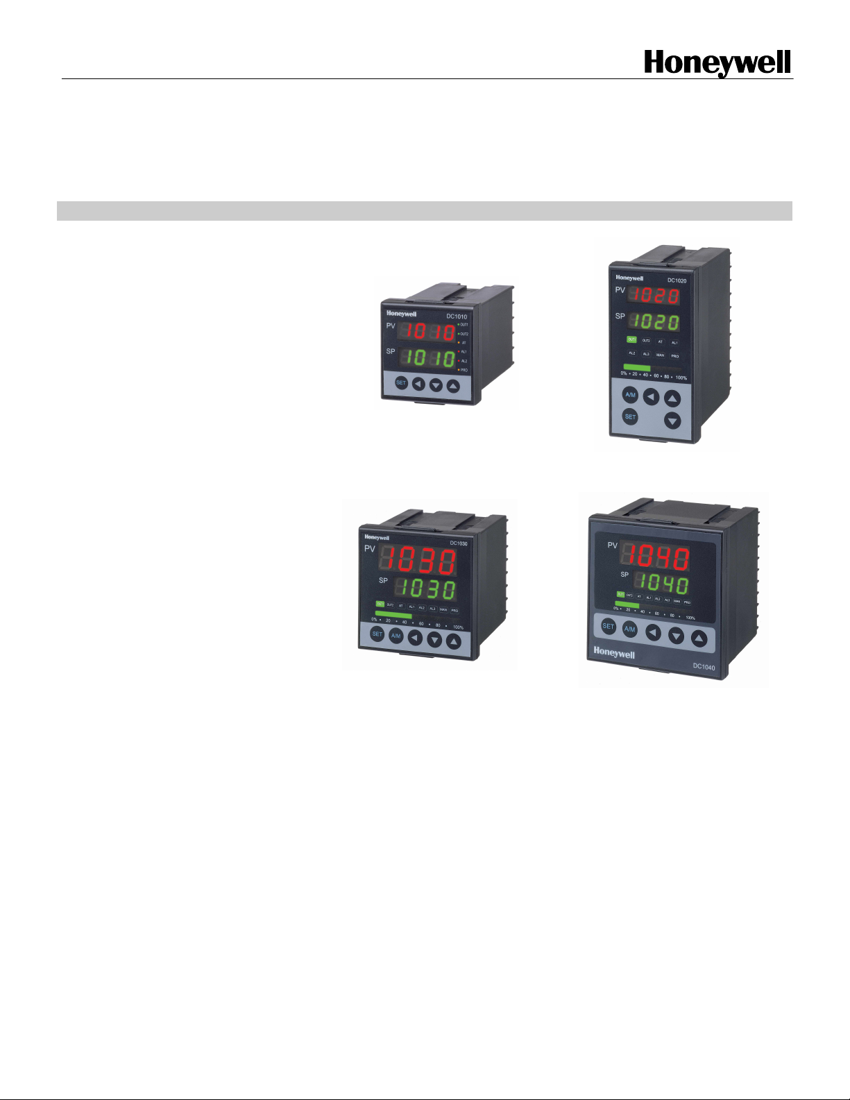
Autotuning capability.
General Purpose DIGITAL CONTROLLERS
DC1010 (1/16 DIN) DC1020 (1/8 DIN)
DC1030 (3/16 DIN) DC1040 (1/4 DIN)
Communications
RS232 or RS485 ASCII protocol
is optionally available. Up to 30
DC1000 Controllers can be
connected to a single host
computer. The host computer
can change the SP, monitor the
PV, the output or change the
configuration of the unit.
Remote Setpoint capability.
Manual / Automatic modes.
Universal Power supply
Operates on any voltage from
85Vac to 265Vac at 50/60Hz.
Large operating range
These instruments can operate
from –20°C to +65°C
(-4°F~149°F)
Page 2

SPECIFICATIONS
Technical data
Thermocouples : K, J, R, S, B, E, N, T, W, PL II, U, L
PV Input
Indication
Control Mode
Type of Input
Input Sampling Time 500 ms
Input Resolution 14 bit (each)
PV/SP Indication 4-digit, 7 segment display
Constant Value Storage System Non-volatile memory (E2PROM)
Indication Accuracy 0.5%FS
Proportional Band ( P ) 0~200% (On/Off action at P=0)
Integral Time ( I ) 0~3600 sec (PD action at I=0)
Derivative Time ( D ) 0~900 sec (PI action at D=0)
Cycle Time 0~150 sec (4~20mA=0, SSR=1, Relay=10)
Dead Band Time 0~1000 sec (dead time compensation)
Relay Output Electromechanical relay
Static relay driver output Voltage Pulse, 20VDC/20mA
RTD : Pt100, JPt100, JPt50
Linear : 4~20mA
• SPDT contacts
• 3A/240Vac
Output
Alarm
Current & Voltage outputs 0~20mA, 4~20mA,
0~5V, 0~10V, 1~5V, 2~10V
Motor Control Output Servo motor valve control (open loop circuit)
Others Phase angle control :
1ϕ SSR, 3ϕ SSR, 1ϕ SCR, 3ϕ SCR
Number Up to 3 (optional)
Modes 17 alarm modes available, hability to ignore the alarm
the first time it occurs :
Deviation high or low alarms.
Deviation alarms.
Band alarm.
High or low alarm.
End of segment alarm.
Program run indication alarm.
Timer alarm.
Timer One timer is associated with each alarm.
Retransmission
output
51-52-03-33 08/03 2
Output Signal SP, PV
Type of Output 4~20mA, 0~20mA, 0~5V, 0~10V, 1~5V, 2~10V
Page 3

2nd Input
Type of Input 4~20mA, 0~20mA, 0~5V, 0~10V, 1~5V, 2~10V
(Remote SP)
Programs
Communication
Operating
conditions
Approvals
Sampling Time 500 ms.
Number 2 programs of 8 segments each.
Type of Communication RS-232 or RS-485.
Rated Power Supply Voltage &
Frequency
Power Consumption 8VA (110V), 12VA (220V)
Ambient Temperature -20°C ~ 65°C (-4°F ~ 149°F)
Ambient Humidity 50 ~ 85% RH (non condensing)
TC & RTD Types & ranges
ASCII protocol.
AC 85 ~ 265V, 50/60Hz
UL Pending.
CE Mark.
°C °F
TC
K
J
R
S
B
E
N
T
W
PL II
U
L
Pt
100
0.0~200.0 °C 0.0~400.0 °C 0.0~600.0 °C 0.0~392.0 °F 0.0~752.0 °F 0.0~1112.0 °F
0.0~800.0 °C 0.0~1000 °C 0.0~1200 °C 0.0~1472.0 °F 0.0~1832.0 °F 0.0~2192.0 °F
0.0~200.0 °C 0.0~400.0 °C 0.0~600.0 °C 0.0~392.0 °F 0.0~752.0 °F 0.0~1112.0 °F
0.0~800.0 °C 0.0~1000 °C 0.0~1200 °C 0.0~1472.0 °F 0.0~1832.0 °F 0.0~2192.0 °F
0.0~1769 °C 0.0~1769 °C 0.0~3216.0 °F 0.0~3216.0 °F
0.0~1769 °C 0.0~1769 °C 0.0~3216.0 °F 0.0~3216.0 °F
0.0~1820 °C 0.0~3308.0 °F
0.0~800 °C 0.0~1000 °C 0.0~1472.0 °F 0.0~1832.0 °F
0.0~1200 °C 0.0~1300 °C 0.0~2192.0 °F 0.0~2372.0 °F
-199.9~400.0 °C -199.9~200.0 °C 0.0~350.0 °C -199.9~752.0 °F -199.9~392.0 °F 0.0~662.0 °F
0.0~2000 °C 0.0~2320 °C 0.0~3632.0 °F 0.0~4208 °F
0.0~1300 °C 0.0~1390 °C 0.0~2372.0 °F 0.0~2372.0 °F
-199.9~600.0 °C -199.9~200.0 °C 0.0~400.0 °C -199.9~999.9 °F -199.9~392.0 °F 0.0~752.0 °F
0.0~400.0 °C 0.0~800.0 °C 0.0~752.0 °F 0.0~1472.0 °F
-199.9~600.0 °C -199.9~400.0 °C -199.9~200.0 °C -199.9~999.9 °F -199.9~752.0 °F -199.9~392.0 °F
0.0~200.0 °C 0.0~400.0 °C 0.0~600.0 °C 0.0~392.0 °F 0.0~752.0 °F 0.0~1112.0 °F
RTD
JPt
100
JPt
51-52-03-33 08/03 3
-199.9~600.0 °C -199.9~400.0 °C -199.9~200.0 °C -199.9~999.9 °F -199.9~752.0 °F -199.9~392.0 °F
0.0~200.0 °C 0.0~400.0 °C 0.0~600.0 °C 0.0~392.0 °F 0.0~752.0 °F 0.0~1112.0 °F
-199.9~600.0 °C -199.9~400.0 °C -199.9~200.0 °C -199.9~999.9 °F -199.9~752.0 °F -199.9~392.0 °F
50
0.0~200.0 °C 0.0~400.0 °C 0.0~600.0 °C 0.0~392.0 °F 0.0~752.0 °F 0.0~1112.0 °F
Page 4

r
Control Algorithms
• PID or ON/OFF control.
• Heat/Cool algorithms with 2 different PID sets.
• Phase angle control
Single Phase
Controller
G1
K1
K2
G2
LN
Thyristor
Module
PROT
1φ LOAD
L
Three Phase
Controller
G1
K1
G2
K2
G3
K3
P
R
O
T
RST
Thyr ist or
Modul e
L
3φLOAD
OFF
ON
In phase angle control, power is regulated by changing the point at which the SCR is turned on within each 1/2 period.
Single Phase
Three Phase
: Output is changed every half-cycle in response to output signals from the Temperature Controller.
: The outputs are changed every 120° in response to signals from the Temperature Controller.
Using this form of control, high-precision temperature control is possible.
• Zero-crossover control
Single Phase
Controller
LN
G1
G2
Three Phase
Controller
RG1
RG2
TG1
TG2
RS T
Thy rist o
Module
P
R
O
T
Thyristor
Module
L
1φLOAD
The term Zero-Crossover means that the SCR's are turned on only when
the instantaneous value of the sinusoidal wave is zero. Power is then
applied for a several continuous half-cycles and then removed for
several half-cycles to achieve the desired load power.
ON
OFF
• Motor position control without slidewire Feedback.
MOTOR VALVE
COM
CLOSE
OPEN
R
S
CONTROLLER
CLOSE
OPEN
COM
OUT2
Relay
OUT1
Relay
Motor position is achieved by using time proportional control
without the need for slidewire feedback from the motor shaft.
Slidewires wear over a period of time, which can result in
poor or intermittent control. This type of control reduces
maintenance requirements and removes the need for the
controller to be calibrated to the motor feed back
potentiometer.
P
R
O
T
L
3φLOAD
51-52-03-33 08/03 4
Page 5

EXTERNAL DIMENSIONS, PANEL CUTOUT
DC1010
68 mm - 2.68 in
50 mm - 1.97 in
6 mm
0.24 in
44 mm - 1.73 in
74.5 mm - 2.97 in
13.5 mm
0.53 in
50 mm - 1.97 in
60 mm - 2.36 in
DC1020
48 mm - 1.89 in
6 mm
0.24 in
86 mm
3.39 in
74.5 mm - 2.97 in
13.5 mm
0.53 in
116 mm
4.57 in
96 mm - 3.78 in
45.5 mm - 1.79 in
45.5 mm - 1.79 in
60 mm - 2.36 in
91mm
3.58 in
45.5mm
1.79 in
DC1030
72 mm - 2.83 in
6 mm
0.24 in
66 mm - 2.60 in
74.5 mm - 2.97 in
51-52-03-33 08/03 5
13.5 mm
0.53 in
91 mm - 3.58 in
69.55 mm
2.74 in
69.55 mm
91 mm - 3.58 in
72 mm - 2.83 in
2.74 in
Page 6

EXTERNAL DIMENSIONS, PANEL CUTOUT
DC1040
96 mm - 3.78 in
6 mm
0.24 in
74.5 mm - 2.97 in
13.5 mm
0.53 in
n
i
n
i
7
8
5
.
7
.
4
3
-
-
m
m
m
m
6
6
1
9
1
HUMAN / MAN INTERFACE
Higher display : 4 digits dedicated to display the PV. In configuration mode, this
display indicates the value of the parameter or the patameter selected.
Lower display : 4 digits dedicated to display the SP ; In configuration mode,
indicates the name of the parameter.
Bargraph : A 10 green LEDs bargraph indicates the value of the output in
percentage.
LEDs :
OUT1 : Status of output 1.
OUT2 : Status of output 2.
AT : When the
AL1 : Status of alarm 1.
AL2 : Status of alarm 2.
AL3 : Status of alarm 3.
MAN : ON if we are in Auto mode. OFF if manuel mode.
PRO : Flickers when a program is running.
Continuously ON when a program is suspended.
OFF when no program is running.
LED is ON an automatic tuning of the parameters is on going.
SET allows to change from one parameter to another. Pressing it for 5 seconds grants access to the
configuration level 1 (PID parameters+locking the instrument).
Pressing simultaneously for 5 seconds on the left arrow and SET grants access to the configuration
level 2 (input type, alarmes, SP limits, field calibration, communication parameters, …).
A/M allows to switch from Auto to
Manual.
When modifying a parameter, pressing this key
allows to change the digit to modify.
116 mm - 4.57 in
90 mm
3.54 in
90 mm
3.54 in
Pressing this key decreases the
parameter or digit being modified.
Pressing this key increases the parameter or
digit being modified.
51-52-03-33 08/03 6
Page 7

MODEL SELECTION GUIDE
• Select the desired Key Number.
• Make One selection each from Tables I through III.
Industrial Measurement and Control
Honeywell Inc.
Japan : Industrial Operations Tokyo, 4-28-1 Nishi-Rokugo Othu-ku, Tokyo 144, Japan,
Asia : Honeywell Asia Pacific Inc., Room 3213-3225, Sun Hung Kai Centre, No. 30 Harbour Road, Wanchai, Hong Kong
Pacific Division : Honeywell Pty Ltd., 5 Thomas Holt Drive, North Ryde NSW Australia 2113
Northern Europe and Southern Africa : Honeywell Ltd., Honeywell House, Arlington Business Park, Bracknell, RG 12 1 EB, U.K.
Central Europe : Honeywell A.G., Kaiserleistraße 39, 63067 Offenbach, Germany
Western and Southern Europe : Honeywell S.A., Bourgetlann 1, 1140 Brussels, Belgium
Eastern Europe : Honeywell Praha, s.r.o., Budejovicka1, 140 00 Prague 4, Czech Republic
Middle East : Honeywell Middle East Ltd., Khalifa Street, Sheikh Faisal Building, Abu Dhabi, U.A.E
Key Number
Key Number
Key Number
Key Number
Dimension
Dimension
Dimension
Dimension
1 48*48mm
1 48*48mm
1 48*48mm
1 48*48mm
2 48*96mm
2 48*96mm
2 48*96mm
2 48*96mm
3 72*72mm
3 72*72mm
3 72*72mm
3 72*72mm
4 96*96mm
4 96*96mm
4 96*96mm
4 96*96mm
Program
Program
Program
Program
C None
C None
C None
C None
P Program
P Program
P Program
P Program
Table I
Table I
Table I
Table I
Table I
Table I
Table I
Output 1
Output 1
Output 1
Output 1
Output 1
Output 1
Output 1
0 None
0 None
0 None
0 None
0 None
0 None
0 None
1 Relay
1 Relay
1 Relay
1 Relay
1 Relay
1 Relay
1 Relay
2 Voltage
2 Voltage
2 Voltage
2 Voltage
2 Voltage
2 Voltage
2 Voltage
3 4~20mA
3 4~20mA
3 4~20mA
3 4~20mA
3 4~20mA
3 4~20mA
3 4~20mA
5 1 ϕSSR
5 1 ϕSSR
5 1 ϕSSR
5 1 ϕSSR
5 1 ϕSSR
5 1 ϕSSR
5 1 ϕSSR
6 3ϕSSR
6 3ϕSSR
6 3ϕSSR
6 3ϕSSR
6 3ϕSSR
6 3ϕSSR
6 3ϕSSR
7 Motor V
7 Motor V
7 Motor V
7 Motor V
7 Motor V
7 Motor V
7 Motor V
8 1 ϕSCR
8 1 ϕSCR
8 1 ϕSCR
8 1 ϕSCR
8 1 ϕSCR
8 1 ϕSCR
8 1 ϕSCR
9 3ϕSCR
9 3ϕSCR
9 3ϕSCR
9 3ϕSCR
9 3ϕSCR
9 3ϕSCR
9 3ϕSCR
A 0~5V
A 0~5V
A 0~5V
A 0~5V
A 0~5V
A 0~5V
A 0~5V
B 0~10V
B 0~10V
B 0~10V
B 0~10V
B 0~10V
B 0~10V
B 0~10V
C 1~5V
C 1~5V
C 1~5V
C 1~5V
C 1~5V
C 1~5V
C 1~5V
D 2~10V
D 2~10V
D 2~10V
D 2~10V
D 2~10V
D 2~10V
D 2~10V
Input
Input
Input
Input
R RTD
R RTD
R RTD
R RTD
T TC
T TC
T TC
T TC
L Linear
L Linear
L Linear
L Linear
Output 2
Output 2
Output 2
Output 2
Output 2
Output 2
Output 2
0 None
0 None
0 None
0 None
0 None
0 None
0 None
1 Relay
1 Relay
1 Relay
1 Relay
1 Relay
1 Relay
1 Relay
2 Voltage
2 Voltage
2 Voltage
2 Voltage
2 Voltage
2 Voltage
2 Voltage
3 4~20mA
3 4~20mA
3 4~20mA
3 4~20mA
3 4~20mA
3 4~20mA
3 4~20mA
A 0~5V
A 0~5V
A 0~5V
A 0~5V
A 0~5V
A 0~5V
A 0~5V
B 0~10V
B 0~10V
B 0~10V
B 0~10V
B 0~10V
B 0~10V
B 0~10V
C 1~5V
C 1~5V
C 1~5V
C 1~5V
C 1~5V
C 1~5V
C 1~5V
D 2~10V
D 2~10V
D 2~10V
D 2~10V
D 2~10V
D 2~10V
D 2~10V
Distributor :
DC10 0
DC10 0
DC10 0
DC10 0
Alarm
Alarm
Alarm
Alarm
Alarm
Alarm
Alarm
0 None
0 None
0 None
0 None
0 None
0 None
0 None
1 1 alarm
1 1 alarm
1 1 alarm
1 1 alarm
1 1 alarm
1 1 alarm
1 1 alarm
2 2 alarms
2 2 alarms
2 2 alarms
2 2 alarms
2 2 alarms
2 2 alarms
2 2 alarms
3 3 alarms
3 3 alarms
3 3 alarms
3 3 alarms
3 3 alarms
3 3 alarms
3 3 alarms
---
---
---
---
Table II
Table II
Table II
Table II
Table II
Table II
Table II
Aux. Output
Aux. Output
Aux. Output
Aux. Output
Aux. Output
Aux. Output
Aux. Output
0 None
0 None
0 None
0 None
0 None
0 None
0 None
1 4~20mA
1 4~20mA
1 4~20mA
1 4~20mA
1 4~20mA
1 4~20mA
1 4~20mA
2 0~20mA
2 0~20mA
2 0~20mA
2 0~20mA
2 0~20mA
2 0~20mA
2 0~20mA
A 0~5V
A 0~5V
A 0~5V
A 0~5V
A 0~5V
A 0~5V
A 0~5V
B 0~10V
B 0~10V
B 0~10V
B 0~10V
B 0~10V
B 0~10V
B 0~10V
C 1~5V
C 1~5V
C 1~5V
C 1~5V
C 1~5V
C 1~5V
C 1~5V
D 2~10V
D 2~10V
D 2~10V
D 2~10V
D 2~10V
D 2~10V
D 2~10V
2nd Input
2nd Input
2nd Input
2nd Input
2nd Input
2nd Input
2nd Input
0 None
0 None
0 None
0 None
0 None
0 None
0 None
1 4~20mA
1 4~20mA
1 4~20mA
1 4~20mA
1 4~20mA
1 4~20mA
1 4~20mA
2 0~20mA
2 0~20mA
2 0~20mA
2 0~20mA
2 0~20mA
2 0~20mA
2 0~20mA
A 0~5V
A 0~5V
A 0~5V
A 0~5V
A 0~5V
A 0~5V
A 0~5V
B 0~10V
B 0~10V
B 0~10V
B 0~10V
B 0~10V
B 0~10V
B 0~10V
C 1~5V
C 1~5V
C 1~5V
C 1~5V
C 1~5V
C 1~5V
C 1~5V
D 2~10V
D 2~10V
D 2~10V
D 2~10V
D 2~10V
D 2~10V
D 2~10V
Table III
Table III
Table III
Table III
Table III
Table III
Table III
Manual
Manual
Manual
Manual
Manual
Manual
Manual
E English
E English
E English
E English
E English
E English
E English
F French
F French
F French
F French
F French
F French
F French
I Italian
I Italian
I Italian
I Italian
I Italian
I Italian
I Italian
GGerman
GGerman
GGerman
GGerman
GGerman
GGerman
GGerman
S Spanish
S Spanish
S Spanish
S Spanish
S Spanish
S Spanish
S Spanish
Comm.
Comm.
Comm.
Comm.
Comm.
Comm.
Comm.
0 None
0 None
0 None
0 None
0 None
0 None
0 None
1 RS232
1 RS232
1 RS232
1 RS232
1 RS232
1 RS232
1 RS232
2 RS485
2 RS485
2 RS485
2 RS485
2 RS485
2 RS485
2 RS485
51-52-03-33 08/03 7
 Loading...