

Page 1

ENS7003R16 KO65 2013
1
DIGITAL BURNER CONTROLLER
DBC2000 SERIES
1. APPLICATION
The Honeywell DBC2000 is a microprocessor-based
integrated bur ner c ontroller for automatically fired
gas, oil or combination fuel industrial single bur ner
power burner appli c ations. The DBC2000 system
consists of the relay m odule and wir ing subbase.
The DBC2000 Standard Model pr ov ides the
minimum requirements to control an industrial
burner system, such as automatic burner
sequencing, fl am e supervision, system status
indicati on, system or self-diagnostics and
troubleshooting. The DBC2000 Enhanced Model
includes an integrated Valve Proofing System,
whilst the Ultimate model includes bus
communication on top of this.
The DBC2000 is programmed to provide a level of
safety, functi onal c apability and features beyond
the capacity of conventional controls.
2. FEATURES
•
Employs a plug-in mounting method
• Uses a microprocessor to improve performance
• Status and fault indication by indic ator LEDs
• A 4-wire firing rate switching circuit controls an air
damper motor or other auxiliary equi pm ent during
start-up of the bur ner .
• Safe start check before and dur ing pre-purge
• Dual flame amplifier for UV, IR or flam e rod sensor
• Automatic rec ycle once per 24h of uninterrupted
heat demand.
• Frontal jac k plug (Ø 3.5mm) to read the flame
signal with a microampere meter.
• An electrical sub base loc k ( r eset and safety limit
terminals are swapped) to avoid that a Standard
model is used systems wired for an Enhanced or
Ultimate model. The DBC2000 cannot start then.
• Safety shutdown occurs on
- malfuncti on of t he burner controller
- failure to ignite the pilot burner or main burner
- loss of flame duri ng r un peri od
- opening of air flow switch during pr e-pur ge, start-
up, run and post-purge period
- flame signal det ection during standby or pre-
purge period
• Integrated Valv e P r oofing System (Enhanced and
Ultimate models only)
• Remote bus communic ation (Ultimate m odel only)
Contents
1. Application 1
2. Features 1
3. Specifications 2
4. Dimensions 5
5. Installation and wiring 6
6. Operation 12
7. Trouble shooting 14
8. Approval s and Maint enanc e 23
Appendix: VPS calc ulation and diagrams 25
PRODUCT HANDBOOK
Importa nt no t e :
Subject to changes without notice.
Please check our web site
http://hic.emea.honeywell.com
for the most recent version of this document.
All rights reserv ed.
Page 2
ENS7003R16 KO65 2013
2
3. SPECIFICATIONS
Table 1: Model Se le c t io n Guide
Model
Descr ipt io n / A pplicati on Supply voltage
DBC2000E10xx (*) Standard model
115V or 230V
(see detailed specs on page 4)
DBC2000E20xx (*) Enhanced model
DBC2000E30xx (*) Ultimate model (future release)
The Enhanced Model incl udes a Valve Proofing System.
The Ultimate model includes both r emote bus communication and a Valve Proofing System.
(*) xx depends on supply voltage and timings. For exact model num ber, plea se ref er to product selection m atrix ot
technical catalogue on http://products.ecc.emea.honeywell.com/europe.
Table 2: Sequence timing Standard Model
Waiting for
AFS
Waiting for
HF
Pre-
purge
Ignition
Pilotonly
Main
trial
Main
stabilization
Post-
purge
Flame
failure
response
300s (max) 300s (max) 35s1) 3s 5s
3s2) 4s2) 15s3) 1s (max)
1)
Default pre-purge time is 35s. Other timings on request, by OS number selection.
2)
Set to 0s. when DBI function is enabled (terminal 22 jumpered to line voltage).
3)
Set to 0s. when “no post-purge” feature is enabled (terminal 12 jumpered to line voltage).
Sequence at flame failure: immediat e lock out
Table 2a: Sequence timin g Enhanced and Ultimate Models
Waiting for
AFS
Waiting for
HF
Pre-
purge
Ignition
Pilotonly
Main
trial
Main
stabilization
Post-
purge
Flame
failure
response
300s (max) 300s (max) 35s1) 3s 5s
3s2) 4s2) 15s3) 1s (max)
1)
Default pre-purge time is 35s. Other timings on request, by OS number selection.
2)
Set to 0s. when DBI function is enabled using the DIP-switches on the front, at the bottom lef t corner (F ig 4-5).
3)
Set to 0s. when “no post-purge” feature is enabled using the DIP-switches on th e f ront, at the bottom left corner ( Fig 4-5).
Sequence at flame failure: immediate lock out
Table 3: Contact ratings
Terminal
Load Contact rating
3 Blower / Fan 3A @ cosφ=0.6
4 Ignition transformer 3A @ cosφ=0.6
5 Intermittent pilot or main (DBI) valves 3A @ cosφ=0.6
6 Interrupted pilot 3A @ cosφ=0.6
7 Main (PI) valves 3A @ cosφ=0.6
12 Main (PI) valve 2 (ENH/ULT models only) 3A @ cosφ=0.6
8, 9, 10, 11 Control motor 0.5A @ cosφ=0.6
21 Alarm 0.5A @ cosφ=0.6
Total load (based on set): Max 8A (Internal Fuse : 10A)
Total load (based on terminal 4,5,6,7): Max 5A (Internal Fuse : 6.3A)
Page 3

ENS7003R16 KO65 2013
3
Table 4: Flame detection systems
Detector
type
Flame detector model no.
Max. lead wire
lengths
Standard stable flame
current on jack plug
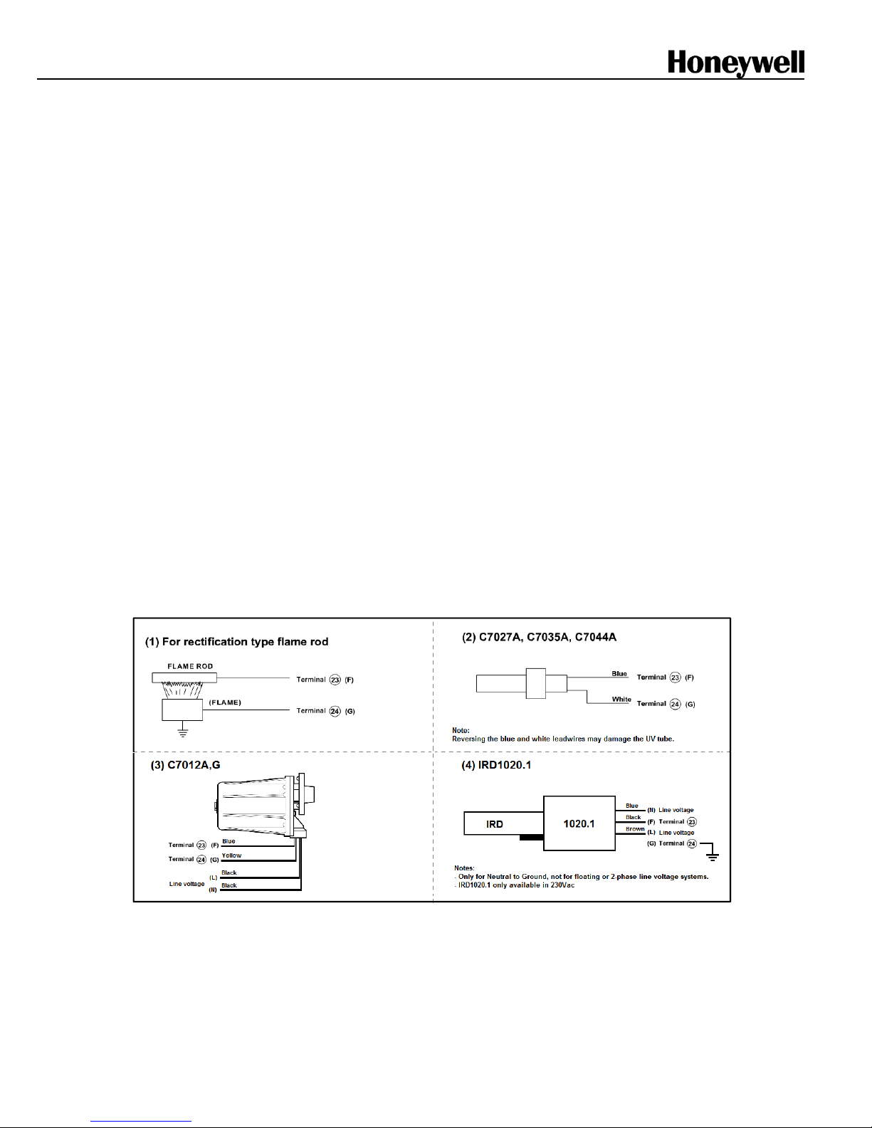
UV detector C7027A, C7035A, C7044A < 100m 4µA (min)
14µA (max)
Flame rod Flame rod or rectifyi ng optical sensors,
C7012A,G (UV) or IRD1020.1 (IR)
< 15m 14µA (min)*
4µA (max)*
* When using a flame rod, the current on the flame jack plug is inverted. S ee also Fig 4-2.
Flame detector l eads are colour coded. The blue lead wire must be connected to the F terminal (T23) and the
white lead wire to the G terminal (T24). The UV sensing tube is polari ty sensit ive. Reversing the lead wires
even momentaril y will destr oy the UV sensing tube.
Page 4

ENS7003R16 KO65 2013
4
Mains input: Supply voltage
220 to 240Vac -15% +10% 50/60Hz or
110 to 120Vac -15% +10% 50/60Hz
Allowable ambien t Temperature & Humidity
-10 °C; +60°C
90% RH max. at 40°C (non-condensing)
Classificatio n to EN298 ( Chapter 4)
F/B/L/L/X/N
Where:
F = Fan assisted
B = Interrupted and Intermittent pilot capable
L (1
st
) = non-volatile lockout after flame loss
L (2
nd
) = non-volatile lockout after flame loss final stage
X = Fixed timings per model number
N = Intermittent operation (non-self-check)
Approvals
CE certification to EN298:2003 (gas, UV & flame rod)
CE certification to EN230:2005 (oil, UV only)
EN746-2 compliant
AGA certified
GOST-R listed
Power consumption
9VA
Protection class
IP40
Mounting
Plug-in mounting method using sub-base
Dimensions
103mm x 103mm x 124mm (W x D x H) incl. sub base
Status in dic a t or LEDs
- Standby
- Purge
- Ignition
- Pilot
- Main
- Modulate
- Flame On
- Alarm
The LEDs will shortl y blink as soon as power is appli ed to t he
DBC2000 and then as soon as there is a heat demand,
indicate the bur ner sequence.
The LEDs are also used to indicate faults. For example, if a
loss of flame signal oc c ur s during RUN, the LEDs for Alarm,
Flame and Main will blink the fault code.
Jack plug
The flame signal can be measured using the jack plug (Ø
3.5mm) on the front, using a microampere meter. The
measuring device m ust be c apable of reading microamperes
between 2 and 15~20 µA.
CAUTION
Although the v oltage on t he jac k pl ug is of low
voltage, it is not consi der ed to be safe when touching
the wires connected to t he jac k plug, in case of a
malfuncti on of t he devi c e. Therefor e av oid touching
the lead wires to avoid an electrical shock.
Reset switch
When the DBC2000 is in Lockout condition* press
the internal or remote reset button one time to reset
the DBC2000 and stop the alarm. The reset button
must be held for a minimum of 3 seconds.
If the heat demand is still present, the DBC2000 will
perform the start sequence normally when the fault
condition has been resolved. Otherwise the lockout
will repeat.
If during the lock out condition the DBC2000 is deenergized and power is reapplied afterwards, the
DBC2000 will rem ain in loc k out ( non-volatile lock
out).
A remote reset push button switc h c an be c onnec ted
between termi nals 15 and 19 (Standard Model) or
between termi nals 15 and 18 (Enhanc ed and
Ultimate Model s). The f unctionality of the remote
reset is the same as the red push butt on on the f r ont
of the device, with one exc eption; the remote reset
may occur only 5 times during 15 mi nutes of
operation, whilst the internal reset button is
unlimited.
* Remark:
Lockout condition refers to the state the DBC2000 is
in after a safety shut-down occurs and the lockout
timing (20 Seconds), plus the post purge timing (15
Seconds - if enabled) have been completed. For
safety reasons the reset button is disabled
immediately aft er a safety shut-down until both of
these above timings are completed.
The lockout timi ng is fixed at 20 seconds for all
models, to allow tim e for the air dampers to return to
the start position, and to allow a safety time between
ignition att em pts, for applications without pre- and
post-purge.
Note: The Alarm and LED’s will indicate the fault
immediately, but c annot be reset until the unit has
progressed to the Lockout Condition.
Remote communication
- Under construction
.
Page 5

ENS7003R16 KO65 2013
5
4. DIMENSIONS
Fig. 1: External Dimensions (in mm)
Fig. 2: Mounting dimensions of sub-base and terminal layout
Page 6

ENS7003R16 KO65 2013
6
5. INSTALLATION AND WIRING
CAUTION
INSTALLATION
When Installing this Product…
1. Read these instructions carefully. Failure to follow
them could damage the produc t or cause a
hazardous condition.
2. Check the ratings giv en in the instructions and
marked on the product t o m ake sure the produc t
is suitable for the application.
3. Installer must be a trained, experienced, fl ame
safeguard service technician.
4. After installation is completed, check out the
product operation as provided in these
instructions.
WARNING
Fire or Explosion Hazard.
Can cause property damage,
severe injury, o r death.
Carefully f ollow safety requirements when installing a
burner control .
CAUTION
Electrical Shock Hazard or Equipment/
Control Damage.
Disconnect power supply before beginning installation,
to avoid electrical shock or equipment damage..
IMPORTANT
1. Wiring connections for the relay modules are
unique; refer to Fig. 3-2 or the appropriate
Specifications for individual subbase wiri ng.
2. Wiring must comply with all appli c able c odes,
ordinances and regulat ions.
3. Wiring must comply with NEC Class 1
(Line Voltage) wiri ng.
4. Loads connected to the DBC2000E must not
exceed those listed on the relay module label or the
Specificati ons; see Table 3.
5. Limits and interlock s must be rated t o
simultaneously c ar r y and break c ur r ent t o the
ignition transformer and fuel valve(s).
6. All external timer s must be listed or component
recognized by aut hori ties who have proper
jurisdiction.
7. For on-off gas-fired systems, some authorities
who have jurisdicti on pr ohibit the wiring of any
limit or operating contacts in series between the
flame safeguard control and the mai n fuel
valve(s).
8. Two UV flame detect or s can be connec ted in
parallel.
9. This equipment generat es, use s and can radiate
radio frequency ener gy and, if not installed and
used in accordance with the instructions, can
cause interfer enc e with radio communications. It
has been tested and found to comply with the
limits for a Class B computing device of Part 15 of
FCC rules, which are designed t o pr ov ide
reasonable protec tion against such interference
when operated in an industrial or commercial
environment. O per ation of this equipment in a
residential area c an c ause interference, in which
case, the users, at t heir own expense, may be
required to take whatever measures are required
to correct this interference.
10. T his digital apparatus complies with the
requirements as stated in the EN298 standard.
11. Do not install the Burner Controll er under any
circumstances in the following locations.
① Where chemicals or corrosiv e gases are
present, such as ammonia, sulfur, chlorine,
ethylene compounds, ac ids, etc.
② Install the relay module where the relative
humidity never reaches the satur ation point.
The relay module is designed t o oper ate in a
maximum 85% relative humi dity continuous,
noncondensing, moisture environment.
Condensing moistur e c an c ause a saf ety
shutdown or damage the devic e.
③ Where temperatures exceed the maximum
specificat ion for thi s device.
④ Where excessive continuous vi br ation exists.
12. Do not bundle power wiring and high voltage
ignition cable with the flame detector wiring, or run
them in parallel wit hin the same conduit. High
voltage cables must be k ept separated at least 10
cm from the Burner Controller.
13. Use proper grounding work in accor danc e with
the engineeri ng standar ds for electrical equipment
14. Connect the high voltage cabl e of t he ignition
transformer pr operl y to t he ignition electrode. A
poor connection c an c ause an el ectr ic al shock or
damage the equipment . Additionally the ignition
transformer must be properly grounded according
the standards.
Page 7

ENS7003R16 KO65 2013
7
REMOVE THE RELAY MODULE FRO M ITS
SUB BASE AND FIX THE SUB BASE
1. Loosen the M3 fixing screw as shown in F ig. 1 by
about eight turns using a Phili ps head screwdriver.
2. Take the subbase and cover with both hands and
unfold them gently. Fold the relay module
upwards, the turni ng point is on the top. Do not
apply excessive force, otherwise damage may
occur.
3. Punch out the needed conduit knockout holes for
the wiring as shown i n Figs 1 and 2, and install the
wiring conduit (s).
4. Using the fixing screws, mount the subbase in the
specified position.
Avoid to overtighten the fixat io n screw on the
front of the device, to avoid damaging the
(Phillips) head o f the screw.
WIRING TH E RELAY MODULE BOTTOM
TERMINALS
1. For applications with a UV detector, remov e the
jumper terminal located at the t erminal block on
the bo ttom of the relay module.
2. For applications using remote communicati on,
connect communication cable to “BUS” terminal
located at the terminal block on the bottom of the
relay module. In addition, set the communic ation
address uring the rotary switches at the bo ttom of
the relay module.
WIRING THE SUB BASE
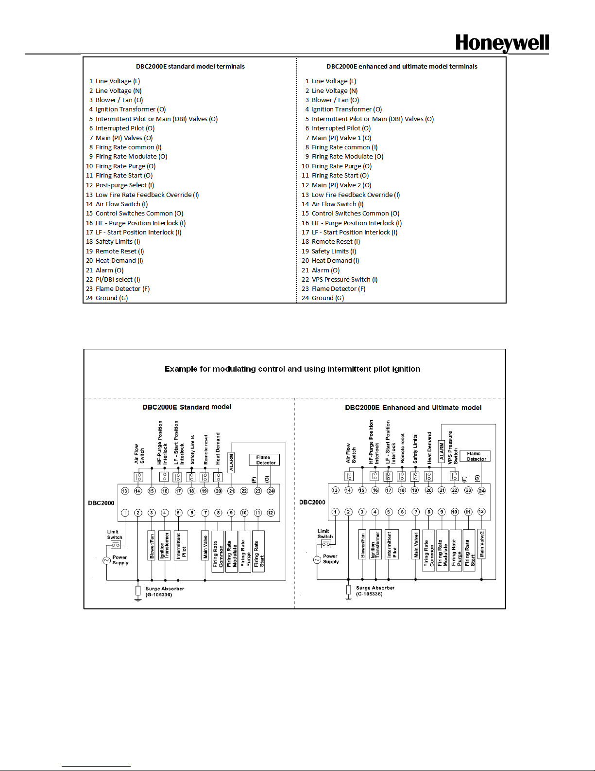
1. Fig. 2 shows the lay out of the terminals on the
subbase, and Figs. 3-1 to 3-3 show examples of
connections to external equipment. Regarding the
wiring to the flame detector, refer to Fig. 4.
2. When using Intermittent Pilot, connect the pilot
valve to Terminal 5. Connect the main valves to
Terminal 7 (Enhanced and Ultimate models:
connect main valve 1 to Terminal 7 and main valve
2 to Terminal 12 for the VPS function)
3. When using Interrupted Pilot, connect the pilot
valve to Terminal 6. Connect the main valv es to
Terminal 7 (Enhanced and Ultimate models:
connect main valve 1 to Terminal 7 and main valve
2 to Terminal 12 for the VPS function)
4. When using direct ignition (DBI), jumper Terminals
15 and 22. And connect the Main(DB I) valves to
Terminal 5.
5. When not using purge positi on interlock, jumper
Terminals 15 and 16.
6. When not using start posi tion interlock, jumper
Terminals 13 and 17.
7. When not purge and start posi tion interlocks,
jumper Terminal s 15 and 16 as well as Termi nals
13 and 17 simultaneously.
8. Connect the safety switc h ci r c uit (lockout
interlocks) bet ween Terminals 15 and 18. The
safety switch cir c uit must be cl osed al way s,
otherwise a lockout oc c ur s immediately.
9. For non-floating mains power grids (Neutral to
Ground), connec t t he Line-L to Terminal 1 and t he
Line-N to Terminal 2. Use a corr ect fuse: 10A fast
bl ow maximum.
10. Check all wiring circuits and assure that the
correct fuse is installed. Check the correct voltage.
11. F inally plug the relay module on to its sub base
and fix it with the M3 fixing screw. Do not overtight
the screw.
12. When using a surge absorber, connect it between
Terminal 2 and application ground.
13. Connect the mains supply volt age usi ng 0.75mm
2
or larger lead wire.
14. Never connect blank stripped wir es to the wiring
sub base. Loose wire strands may c ause short
circuits to elec tric ally safe contacts which may
cause an electri c al shock haz ar d.
Always use cable lugs to attach the wires to th e
sub base.
See Fig 2-1 for do’s and don’ts about wiring.
Fig. 2-1: Wiring the sub base terminals
Page 8
ENS7003R16 KO65 2013
8
Note: terminals 18 and 19 are swapped for the Standard and Enhanced/Ultimate models.
This is to prevent that a Standard model can be used by mistake in a system that is wired for an Enhanced or Ultimate model.
Fig. 3-1: Terminal layout
Fig. 3-2: Example of wiring to external equipment (see fig 3-3 for more)
Page 9
ENS7003R16 KO65 2013
9
Fig. 3-3: More examples of wiring to external equipment
Fig. 4-1: Wiring a flam e detector
CAUTION
There is line voltage on fl am e sensor inputs. Don’t touch the lead wires of the UV detector or the flame sensing
electrode t o avoi d an electri c al shock.
Page 10

ENS7003R16 KO65 2013
10
Flame signal monitoring
Fig. 4-2: Real flame current versus reading on frontal jack plug.
Note:
The flame signal strengt h on the flame current jack plug is only for reference
and can vary between differ ent
DBC2000 devices.
When measuring the fl am e signal c ur r ent direc tly in the flame sensor wiring whilst:
1. Using a flame rod, the (multi -)meter will show the real flame current in µA.
2. Using a UV sensor (C7027, C7035 or C7044), the current in the sensor lead wires will be in the range of
20…25mA (inverted values).
Fig. 4-3: Measuring flame signal with multi meter (µA range selection) using a jack plug.
STD & ENH Models (flame detector sel ec t only) ULT Model (bus connector and address switches)
Fig. 4-4: Position of flame sensor selection jumpers and bus connector on the back of the DBC2000.
Page 11
ENS7003R16 KO65 2013
11
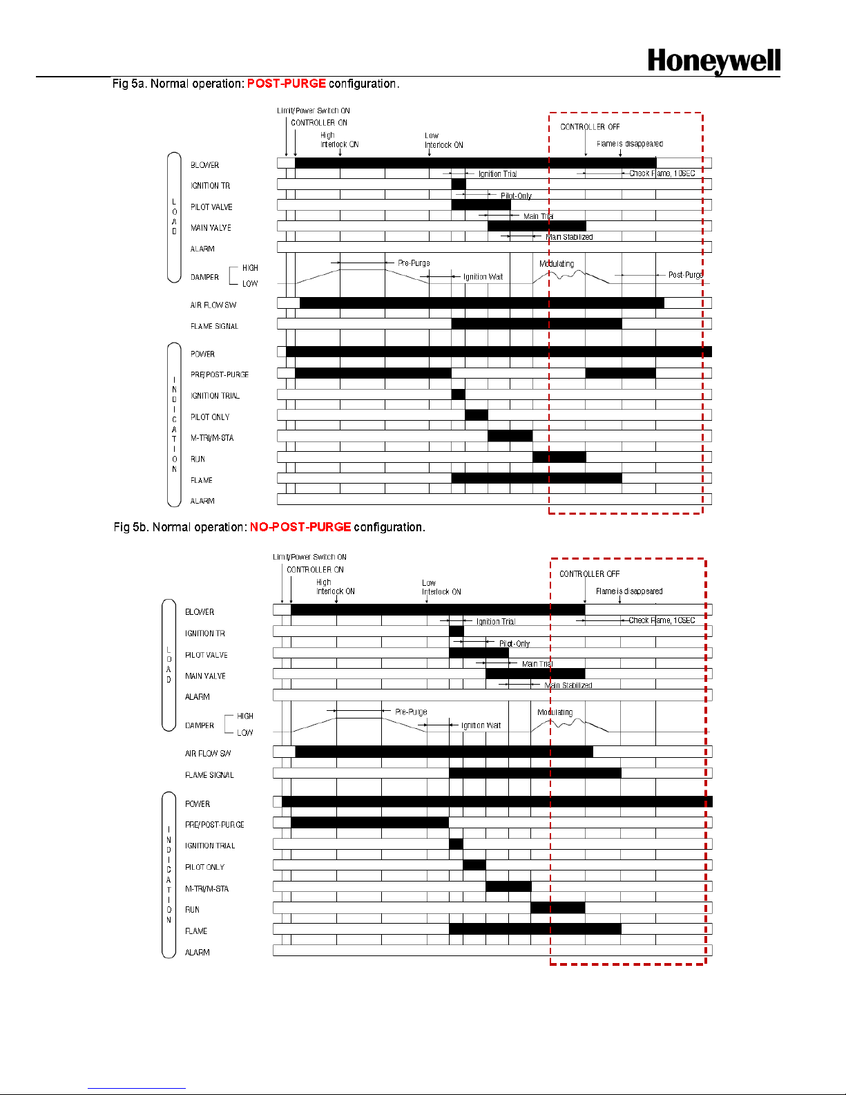
SETTING THE OPTIONAL FEATURES
1. Post-purge or no post-purge
Post-purge mode
(default for all DBC2000E
models): before going to standby after heat
demand has ended, the DBC2000E performs a
15s post-purge cycle t o ventilate the burner
chamber, with the bl ower swit c hed on and the
firing rate in low positi on to save energy.
No post-purge mode
(selectabl e option): the
DBC2000E goes to standby with the blower
switched off immediately after heat demand ends
and the firing rate goes to low position.
STD model:
To enable no post-purge, apply line voltage to
terminal 12 on the wiring base. Practically this
means that a jumper is placed bet ween term inals
1 (L) and 12.
ENH/ULT models:
To enable no-post-purge, make the correct DIPswitch setti ng on the front of t he DB C2000E .
SW1 = POSTPURGE select.
Factory set to post-purge (SW1=off).
See fig. 4-5 to locate the DIP switches.
2. Pilot Ignition (PI) or Direct main
Burner Ig nit i on (DBI)
PI mode
(default): the main burner is ignited
indirectly by usi ng an interrupted or intermittent
pilot flame. Aft er the pilot is ignited and
stabelized, the DBC2000E goes for a second trial
of ignition (2
nd
safety and main stabilization are
3s) to ignite the mai n burner.
DBI mode
(selectabl e option): the intermittent
pilot ignition cycle is used to ignite the main
burner directl y via the spark igniter. The second
trial for ignition has become redundant in this
mode. In DBI mode the 2
nd
safety and main
stabilizati on times are 0s and DBC2000E goes
straight into running/modulate after pil ot
stabilization.
STD model:
To enable DBI mode, apply li ne v oltage to
terminal 22 on the wiring base. Practically this
means that a jumper is placed bet ween term inals
1 (L) and 22.
ENH/ULT models:
To enable DBI mode, make the correct DIP-switch
setting on the front of t he DBC2000E.
SW2 = DBI/PI select. Factory set to PI (SW2=off).
See fig. 4-5 to locate the DIP switches.
3. Valve Proofing System – VPS
(ENH/ULT models only)
Connect a gas pressure switc h ( such as the
C6097A2210) to terminal 22 on the wiring base
(N.O. contact).
Rule of thumb: adjust t he pr essure switc h to 0.5x
the inlet pressure.
Table 5: VPS function:
VPS enabled
SW3 = on
VPS is being perform ed
VPS disabled
SW3 = off
VPS is not used (default)
VPS pre-config
SW4 = on
SW5 = off
The VPS test cycle i s
performed duri ng pr e-purge
cycle, right aft er the heat
demand has started.
VPS post-config
SW4 = off
SW5 = on
The VPS test cycle i s
performed ri ght after the heat
demand has ended.
VPS both config
SW4 = on
SW5 = on
The VPS test cycle i s
performed before and after
the heat demand cycle.
Table 6: VPS timing:
VPS test time
25s
SW6=on
SW7=on
VPS test time
20s
SW6=on
SW7=off
VPS test time
15s
SW6=off
SW7=on
VPS test time
10s (default)
SW6=off
SW7=off
SW1: Post-p urg e use (default: off = post-purge enabled)
SW2: DBI/PI select
(default: off = PI enabled)
SW3: VPS use
(def ault: off = dis abled)
SW4: VPS pre-config
(default: off = dis abled)
SW5: VPS post-config
(default: off = disabled)
SW6: VPS test time
(default: off = see timing table)
SW7: VPS test time
(default: off = see timing table)
SW8: Not used (for future use)
Note for DIP switches:
on = upwards
off = downwards
Fig 4-5 Configurati on DIP switc hes (VPS) on the front of the DB C2000E (ENH/ ULT only)
Page 12

ENS7003R16 KO65 2013
12
6. OPERATION
NORMAL OPERATION
Table 7: Normal operation seq uence
Inputs
Operation of DBC2000 and device Indicator LED *
HEAT DEMAND SW OFF
AIR FLOW SW OFF
SAFETY LIMI T SW ON
The power supply voltage is appl ied across Terminal 1 and
2. When no flame signal is present, the combustion airflow
switch is opened (T14=OFF) and safety lockout
circuit is
closed (ON), it is possible t o star t.
●○○○○○○○
HEAT DEMAND SW ON
START Pos SW ON
PURGE Pos SW OFF
The blower is energiz ed (T3) . Fi ri ng r ate goes to PURGE
position. Air flow switch closes (T14=ON) as soon as air flow
is present.
●●○○○○○○
AIR FLOW SW ON
START Pos SW OFF
PURGE Pos SW ON
The pre-purge timer star ts counting as soon as PURGE
interlock is closed (T16=ON).
PURGE Pos SW OFF
After the completi on of pre-pur ge timing, firing rate goes to
START position.
The ignition wait timer star ts counting as soon as the START
position interlock is closed (T17=ON).
START Pos SW ON
After completion of the ignition wait timing, t he Igniti on
sequence starts. The I gnition transformer is energiz ed. The
Intermittent and Interrupted pilot valve out puts are energized
(T5 and T6).
●○●○○○○○
●○●○○○●○
FLAME ON
When a flame is detected after the ignition trial has ended
(Safety1), t he pilot stabilization tim e starts.
●○○●○○●○
After completion of the pilot-stabilization time, the Main
valves are energized (T7=ON). Note: Enhanced Model: also
(T12=ON).
The Main trial for igni tion takes place (Safety2).
●○○○●○●○
After completion of the main trial time, Interrupted pilot valve
is deenergized (T5=OFF). The Main stabilization time starts.
●○○○●○●○
PURGE & START Po s SW
IGNORED
After completion of the main stabilization time, the firing rate
goes to modulati on posi tion and releases control to an
external modulation device.
●○○○○●●○
HEAT DEMAND SW OFF
The intermittent pilot valve and main valves are deenergized
(T6=OFF and T7=OFF). Note: Enhanced Model: also
(T12=OFF). Firing rate moves to PURGE position.
The post-purge timi ng takes pl ac e.
●●○○○○○○
FLAME OFF
After the completi on of t he postpur ge time, the blower is
deenergized and firing rate moves to START position.
●○○○○○○○
AIR FLOW SW OFF
SAFETY L IMIT SW ON
After the air flow switch goes OFF, DBC2000E returns to the
STANDBY conditi on, wait ing for the next heat demand.
* For LED indic ation, ○ means ‘off’, ● means ‘illuminated’.
* Th e LEDs are arranged in the following order: Standby, Purge, Ignition, Pilot, Main, Modulate, Flame and Alarm at the left front
side of the DBC2000.
Page 13
ENS7003R16 KO65 2013
13
Page 14

ENS7003R16 KO65 2013
14
7. TROUBLE SHOOTING
ERROR T YPES AND SAFE SHUTDOWN
If a critical error related to safety operation (such as a l oss of flame, opening of the air flow switch during the
ignition trial and r un sequence) is detected, the DBC2000 instantly goes into lock-out and goes to pre-purge stat us.
If a non critical error is detected (such as opening of the air flow switch during post-purge), DBC2000 holds the
sequence during the lock-out time, allowing time for the error to rectify, and then goes into lock- out.
For all types of errors, the status LEDs indicate the status information to the operator.
Fig. 6 to Fig. 13 show the sequence of DBC2000 i n case of some err or. A nd Table 8 shows the statu s of LEDs for
each error.
The product handbook (E NS 7003) shows the different scenarios for possible failures.
Page 15

ENS7003R16 KO65 2013
15
Page 16

ENS7003R16 KO65 2013
16
Page 17

ENS7003R16 KO65 2013
17
Page 18

ENS7003R16 KO65 2013
18
Page 19

ENS7003R16 KO65 2013
19
Page 20

ENS7003R16 KO65 2013
20
Page 21

ENS7003R16 KO65 2013
21
Page 22

ENS7003R16 KO65 2013
22
Table 8: Error co ndition and LED stat us
Sequence
Error condition
Indicator LED
status (*1)
All
Safety limit s opened at any tim e (no voltage present at T18 (STD model) or
T19 (ENH/ULT model)
●○○○○○○◐
Standby (*2)
Air flow switch remains ON (closed) for more than 5 minutes, or
START position
interlock switch remains OFF(opened) for more than 5 minutes.
●◐○○○○○◐
Flame signal is present
●○○○○○◐◐
Blower motor is energized
●◐○◐◐○○◐
Pre-purge
Air flow switch remains OFF for more than 5 minutes after the heat demand has
started.
●◐○○○○○◐
PURGE pos ition int erlock swi tch remai ns OFF for more than 5 minutes after the heat
demand started.
●◐◐◐○○○◐
Both PURGE and START position interlocks ON at the same time during prepurge
period
●◐◐◐○○○◐
START position interlock remains OFF more than 5 minutes after pre-purge has
finished
●◐◐◐○○○◐
Air flow switch goes ON within 5 minutes after the heat demand started, but air flow
switch goes OFF again.
●◐○○○○○◐
Flame signal is present.
●◐○○○○◐◐
Ignition Standby
Air flow switch goes OFF
●◐○○○○○◐
Flame signal is present
●◐○○○○◐◐
Pilot Ignition
Air flow switch goes OFF
●◐◐○○○○◐
Ignition failure (flame signal is not present after ignition-trial).
●○◐○○○○◐
Pilot only
Air flow switch goes OFF
●◐○◐○○○◐
No flame signal
●○○◐○○◐◐
Main ignition
Air flow switch goes OFF
●◐○○◐○○◐
No flame signal
●○○○◐○◐◐
Main ignition
Stabilization
Air flow switch goes OFF
●◐○○◐○○◐
No flame signal
●○○○◐○◐◐
Run
Air flow switch goes OFF
●◐○○○◐○◐
No flame signal
●○○○○◐◐◐
Post-purge
No power is supplied to Ter minal 3 b ecause of intern al rel ay contac t fail ure.
●◐○◐◐○○◐
Flame signal is present for more than 10 seconds after heat demand has ended.
●○○○○○◐◐
Air f low switch keeps ON more than 5 minutes a f ter po st-purge.
●◐○○○○○◐
All
1. Line voltage out of specs for more than 2 seconds
2. Line frequency out of range for more than 2 seconds
3. Excessive noise on power line or in the ar ea
4. Internal device problem : CPU clock out of sync
●○○○○○○●
*1 : For LED indication, ○ means ‘off’, ● means ‘illuminat ed’, ◐ means ‘blinking’.
The LEDs are arranged in the following order: Standby, Purge, Ignition, Pilot, Main, Modulate, Flame and Alarm at the left
front side of the DBC2000.
*2 : If an error occurs during Standby, the DBC2000 will not lock-out but LEDs indicate the current error status.
In this case, the DBC2000 cannot start before the error is resolved.
Page 23

ENS7003R16 KO65 2013
23
8. Approvals and Maintenance
Declaration of Conformity
Honeywell Technologies Sàrl
Z.A. La Pièce 16
1180 Rolle
Switzerland
declares under it ’s sole respon si bility that the foll owing product family of burner controllers:
DBC2000 E 1xxx / DBC2000 E 2xxx
to which this statem ent relates, is:
• in conf ormit y with the essential requirements of the Gas Appliance Directive 2009/142/E C
based on EN 298
and in conformity with the type as described in the EC type-examination certificate issued
by DVGW CERT GmbH in Bonn with pin number
0085CM0138
• in conf ormity with the essential requirem ents of the Low Voltage Directive 2006/95/ E C
based on EN 60730-2-5
• in conf ormit y with the essential requirements of the EMC Direct ive 2004/108/EC on immunity
based on EN 298 immunity requir em ents
Conformity with the essential requirements of the EMC Directive 2004/108/EC on emission can only be
determined in the application.
This product is under surv eillance at KIWA Nederland BV.
Emmen, October 2011
Signed for and on behalf of Honeywell Technologies Sàrl,
A.Veld
Manager Standards & Approvals
Page 24

ENS7003R16 KO65 2013
24
Maintenan ce a nd service
The designed lifetime* of this product is 10 years, based on date code, or 1.000.000 cycles under norm al
conditions, accor ding to:
a) the standard EN 298
b) the table on designed lifetime as stated on the Afecor website http://www.afecor.org/
We cannot assume that the pr oduc t can be safely used beyond the mentioned designed lifetime. This lifetime is
based on use of the control accor ding m anufacturer’s instructions.
Regular inspection of the control by authorized per sonnel in ac c or danc e with guidelines of the applianc e
manufacturer is required.
After reaching the designed lifetime the product has to be repl ac ed by authorized personnel.
Note: * Warranty as opposed to design ed l ifet ime is described in the delivery terms.
Page 25

ENS7003R16 KO65 2013
25
APPENDIX: Calculations for VPS
General
The m aximum all owable lea k-rate (according EN676 and
EN746-2) is 0,1% of the maximum burner capacity. The test
time necessary to d etect a fail ing v alve is a fun c tion of:
- Inlet pr essur e
- Test volume
- Burner capacity
Wh en the v olume between two safety va lves i s big ger it takes
more time (in c ase of a l eaki ng val ve) to change the status of
the gas pressure swi tch (GPS) .
The switching point of the GPS is set to 50% of the maximum
inlet press ure. T he test peri od Tp i s calculat ed from the
inletpressure Pi, the test volume Vp (see Table a.) and
maximum burner capacity Qm. In a formula:
2 x Pi x Vp
Tp = --------------- [s]
Qm
Pi = inlet press ure [mbar]
Vp = test volume, s ee als o Table a [dm
3
]
Qm = burner capacity [dm
3
/h]
Tp = test time [s ]
Important
The total volume Vp h as to be c alculat ed with all volumes
betw een t he tested v alves : int ernal vol umes of valv es and all
pipes.
Calculation examp les
Example 1
Calculation of the minimum test time (per valv e) in a 2”
threaded pipe train.
Pi = 150 mbar
Qm = 60 dm
3
/h
Gas valv es used: 2” size with 0. 5 meter pip e.
To be calculated: Tp [s]
Calculation:
From Table a. :
2“ @ L=0.5m Vp = 2.3 dm
3
2 x 150 x 2.3
Tp = ---------------- [s]
60
Using the formula above, the minimum test time Tp = 11.5s
The DBC2000E2 must be set to 15s tes t time (see page 11 ).
Example 2
NOTE: to allow a 3-valve configuration, an external SPDT
relay needs to be added, when used incombination with VPS.
See schematic drawing below.
Calculation of the mini mum test time (per valve) in a DN80
flanged pipe train, where a 1” bypass valve is used.
Pi = 150 mbar
Qm = 100 dm
3
/h
Gas valv es used: DN8 0 s ize with 1 meter pipe (L1).
Byp ass valve: 1” valve with 0.5 met er pipe (L2).
To be calculated: Tp [s]
Calculation:
From Table a. :
DN80 @ L1=1m Vp1 = 6.9 dm
3
1” @ L2=0.5m Vp2 = 0.44 dm3
There is only 1” bypa ss valve, that r educes the total volume
by 0.5x the volum e @ L=0m Vp3 = 0.19 dm
3
Vp = Vp1 + Vp2 – (0.5 x Vp3) = 7.245 dm
3
2 x 150 x 7.15
Tp = ------------------ [s]
100
Using the formula above, the minimum test time Tp = 21.735s
The DBC2000E2 must be set to 25s test time (see page 11).
Page 26

ENS7003R16 KO65 2013
26
Tab le a.
Volumes in dm3 for ga s valves like Hon eywel l VE-series (Vp) with pipe length L (including V1 and V2). For combi blocks, like
VQ-M series and direct linked valves, use the values shown under L=0m.
Diameter
Length between valves [m]
0
0.5 1 1.5
2
per extra
meter
¼”
0.06
0.1
0.14
0.18
0.22
0.08
½”
0.06
0.15
0.24
0.33
0.42
0.18
¾”
0.12
0.28
0.43
0.59
0.74
0.31
1”
0.19
0.44
0.68
0.93
1.2
0.49
1¼”
0.69
1.1
1.5
1.9
2.3
0.8
1½”
0.71
1.4
2.0
2.7
3.3
1.3
2”
1.3
2.3
3.3
4.2
5.2
2.0
2½”
2.7
4.4
6.0
7.7
9.3
3.3
3”
2.9
5.4
7.9
10
13
5
DN65
3.2
4.9
7.5
8.2
9.8
3.3
DN80
4.4
6.9
9.4
12
14
5.0
DN100
6.5
10.5
14.4
18
22
7.9
Threaded connections: sizes in inches.
Flanged connections: sizes in DN
If L = 0m it means that valves are directly linked without pipe connections. Also applicable for combi-blocks (VQ-M series).
Page 27

ENS7003R16 KO65 2013
27
Page 28

ENS7003R16 KO65 2013
28
Page 29

ENS7003R16 KO65 2013
29
Page 30

ENS7003R16 KO65 2013
30
Page 31

ENS7003R16 KO65 2013
31
Page 32

ENS7003R16 KO65 2013
32
Page 33

ENS7003R16 KO65 2013
33
Page 34

ENS7003R16 KO65 2013
34
 Loading...