

Page 1
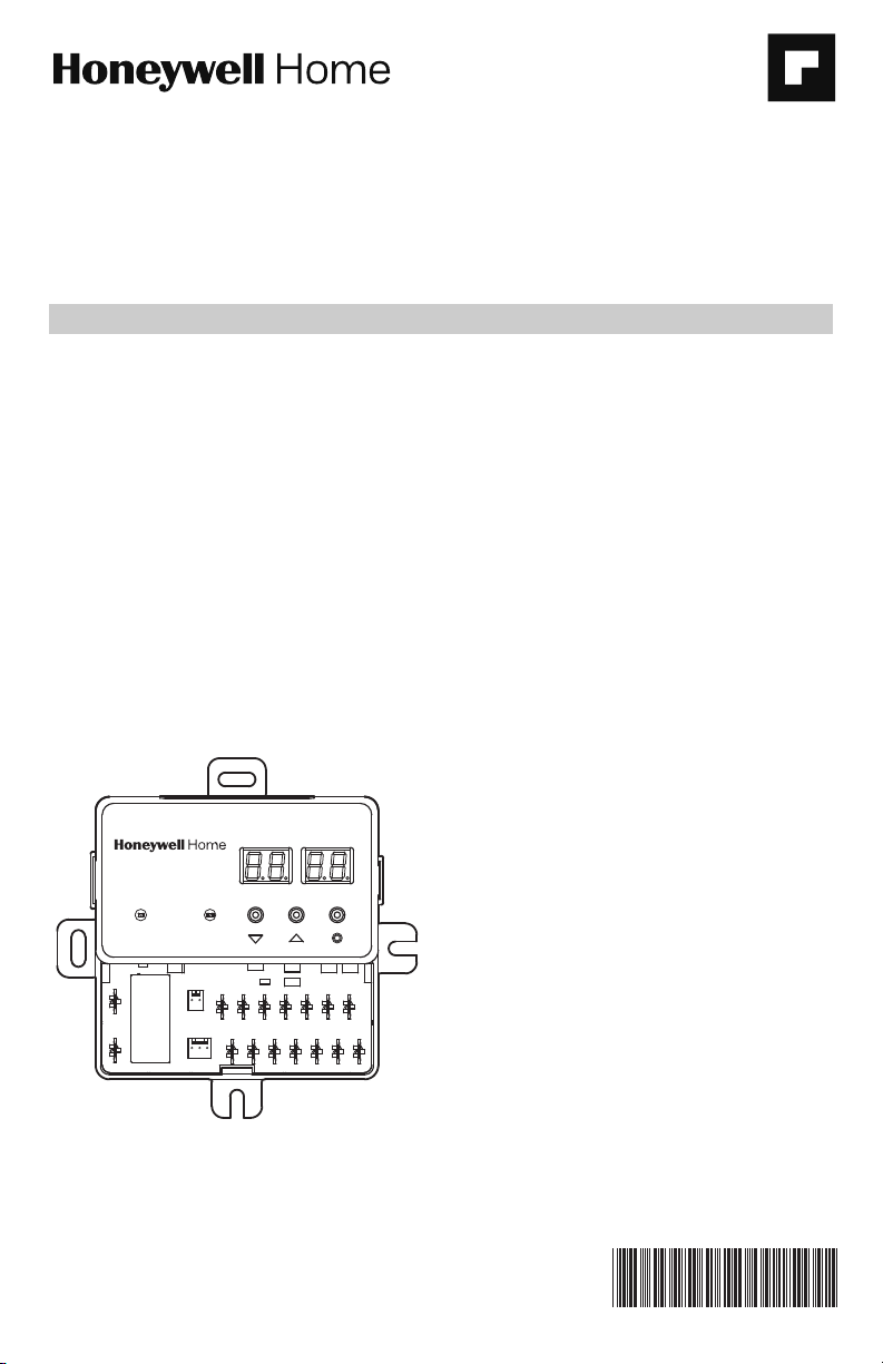
DB7110U Universal Heat Pump
MENU
SETTING
SYSTEM
FAULT
M37637
DB7110U-DEFROST CONTROL
Defrost Controller
INSTALLATION INSTRUCTIONS
APPLICATION
The DB7110U Universal Heat Pump Defrost
Controller is a heat pump defrost control used in
single stage heat pump appliances. This product
replaces over 260 OEM and competitive controls and
can be easily programmed to meet the requirements
of virtually any single stage heat pump. See Table 2,
“Compatibility Chart.,” on page 5.
FEATURES
The DB7110U provides:
• Universal defrost control for single stage heat
pumps
• LED display for easy setup and configuration
• Small, square footprint for easier installation
• Demand and timed defrost modes
• System status and fault indication
• Selectable reversing delay to limit noise when
going in and out of a defrost cycle
• Fault history for easy troubleshooting
SPECIFICATIONS
Electrical Ratings
Input Voltage: 24VAC, 60Hz
Max. Input Current: 200mA
Compressor Contactor: 1A @ 24VAC
Outdoor Fan:
1/2HP motor
5A full load, 30A locked rotor, 240VAC.
Aux Heat: 1A @ 24VAC
Reversing Valve: 1A @ 24VAC
All outputs rated for 100,000 operations.
All terminals except FAN-IN and FAN-OUT are NEC
Class 2 low voltage.
Environmental Ratings
Operating Temperature Range: -40F to 150F
Humidity Limits: less than 95% (non-condensing)
Fig. 1. DB7110U1000.
INSTALLATION AND CONFIGURATION
Overview
When Installing This Product…
1. Read these instructions carefully. Failure to fol-
low instructions can damage the product or
cause a hazardous condition.
2. Check ratings given in these instructions and
on the product to make sure the product is suitable for your application.
3. Installer must be a trained, experienced service
technician.
4. Use these instructions to check out the product
operation after installation.
34-00032-01
Page 2
DB7110U UNIVERSAL HEAT PUMP DEFROST CONTROLLER
WARNING
WARNING
M37663
M37664
Electrical Shock Hazard. Can cause severe
injury, death or property damage.
Disconnect power supply before beginning
installation to prevent electrical shock or
equipment damage. More than one disconnect
may be involved.
Control Location
1. Before removing the old control, make note of
the wire connections to ensure the wires will be
connected to the correct terminals of the
DB7110U.
2. Mount DB7110U inside the junction box on the
outdoor unit using the two included self-drilling
sheet metal screws.
3. Use the control as a template to drill new mounting holes if necessary.
4. If the mounting tabs interfere with other components in the junction box, break/cut off the
unused mounting tabs prior to tightening the
mounting screws.
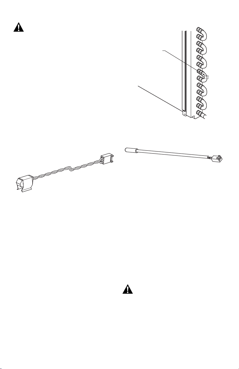
Coil Sensor Location
Fig. 2. Coil Sensor.
1. The outdoor coil sensor must be used. Without
the coil sensor, the DB7110U cannot determine
when to defrost. The coil sensor included with
the DB7110U replaces the existing defrost thermostat or coil sensor installed on the unit.
2. Place the sensor on the coil where the OEM sensor/thermostat was located. If replacing a
defrost thermostat, note the original settings for
proper adjustment of the termination and
enable temperatures on the DB7110U. They are
often marked with their open and close points. A
thermostat marked L60-25F for example would
correspond to a Termination Temperature of
60degF and an Enable Temperature of 35degF
(60deg-25deg).
3. If the location of the OEM sensor/thermostat is
inaccessible or difficult to access, place the new
coil sensor on the coil loop nearest the expansion valve where refrigerant is entering the coil
during the heating mode. This location gives the
largest temperature difference between the air.
4. Ensure the coil sensor is clamped tightly to the
coil. It may be desirable to add insulation to the
sensor to yield more accurate readings,
although this is generally not needed.
Wiring
SENSOR
M37638
Fig. 3. Coil Sensor Mounting.
OUTDOOR AIR SENSOR LOCATION
Fig. 4. Air Sensor.
1. The outdoor air sensor is optional. Using the
outdoor air sensor will enable the DB7110U to
implement a more advanced defrost algorithm
that determines to defrost based on the relationship between coil and air temperatures. Without
the air sensor, the DB7110U defrosts when the
coil temperature is below the Enable Temperature for the Defrost Cycle Time. It is advisable to
use the air sensor if possible as it may reduce the
number of unnecessary defrosts that are common among defrost timers.
2. Mount the air sensor such that the capsule is
hanging in air near the outdoor coil.
3. Do not locate the air sensor too close to the coil
that sensor readings are influenced by it.
4. Do not mount the air sensor in direct sunlight.
5. The air sensor capsule should not be in contact
with metal or some other material that may
change its readings.
Electrical Shock Hazard. Can cause severe
injury, death, or property damage.
Disconnect power supply before beginning
wiring to prevent electrical shock or equipment
damage. More than one disconnect may be
involved.
1. Make sure the wiring complies with all local
codes and ordinances.
2. If the low voltage wiring is bare wire with no terminals, wire nut them to the included wiring pigtails. Do not crimp terminals to solid wire.
34-00032—01 2
Page 3
DB7110U UNIVERSAL HEAT PUMP DEFROST CONTROLLER
A
LPC
HPC
CONTACTOR
AUX
REVERSING
VALVE
FAN-IN
FAN-OUT
R
C
O/B
W
Y
AIR
SENSOR
(OPTIONAL)
COIL
SENSOR
INDOOR
EQUIPMENT
OUTDOOR
EQUIPMENT
FAN
DB7110U
L1
L2
COMPR
RV
HIGH
PRESSURE
SWITCH
LOW
PRESSURE
SWITCH
AIRCOIL
IF THE PRESSURE SWITCH(ES) ARE IN SERIES
WITH THE CONTACTOR, JUMPER THE
ONBOARD CONNECTIONS. DO NOT BYPASS
ANY PROTECTIVE PRESSURE SWITCHES.
M37758
3. Check the line voltage connections on the fan
relay to ensure they are tight, in good connection, and more than 1/4" away from any part of
the appliance enclosure.
4. Plug in the outdoor sensor (if used) and the coil
sensor.
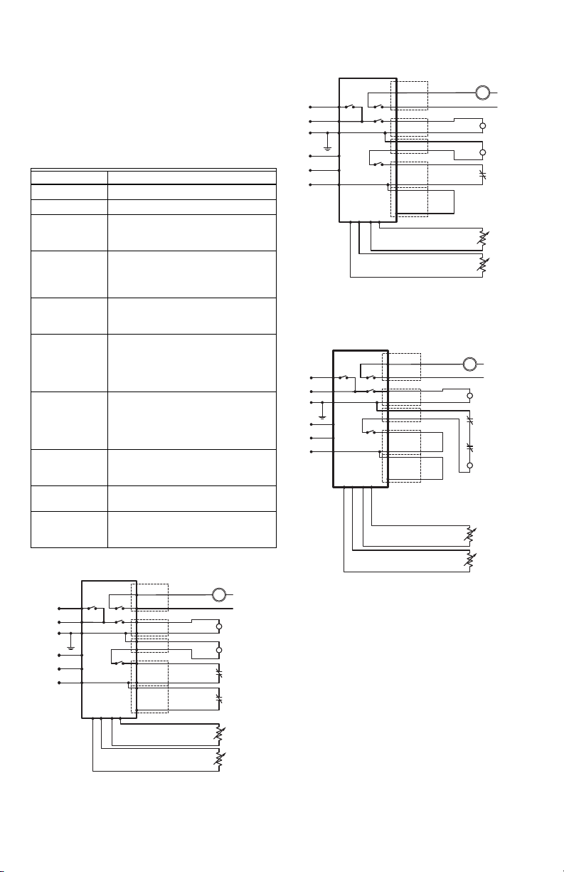
5. Reference the wiring diagrams in Figs. 5 to 8 to
aide in proper appliance wiring.
Table 1. Class 2 Low Voltage Terminations,
24V 60Hz.
Name Function
R (24V) 24V Hot
C (COM) 24V Common
W Aux/emergency heat request from
Y Compressor request from
O Reversing valve request from
HPC
(2 Terminals)
LPC
(2 Terminals)
AUX Output to auxiliary/emergency heat
COMPR
(2 Terminals)
RV
(2 Terminals)
thermostat – W requests will cause
the AUX output to be energized.
thermostat – Y requests will cause
the COMPR and FAN terminals to be
energized.
thermostat – controls the status of
the RV output.
High pressure cutout/switch – these
terminals must be shorted for
compressor operation. Never
bypass protective pressure
switches.
High pressure cutout/switch – these
terminals must be shorted for
compressor operation. Never
bypass protective pressure
switches.
– energized during a defrost cycle or
when requested by W input.
Output to compressor contactor –
energized by Y request.
Output to reversing valve –
energized by O input and as
required by a defrost cycle.
INDOOR
EQUIPMENT
UX
R
C
O/B
W
Y
Fig. 6. Wiring diagram for systems with no low
DB7110U
FAN-OUT
FAN-IN
RV
COMPR
HPC
LPC
AIRCOIL
pressure switch.
OUTDOOR
EQUIPMENT
FAN
REVERSING
CONTACTOR
PRESSURE
(OPTIONAL)
SWITCH
SENSOR
SENSOR
L2
L1
VALVE
HIGH
AIR
COIL
M37757
OUTDOOR
EQUIPMENT
FAN
REVERSING
CONTACTOR
PRESSURE
PRESSURE
(OPTIONAL)
SENSOR
L2
L1
VALVE
HIGH
SWITCH
LOW
SWITCH
AIR
SENSOR
COIL
INDOOR
EQUIPMENT
AUX
R
C
O/B
W
Y
Fig. 5. Wiring diagram with pressure switches
DB7110U
FAN-OUT
FAN-IN
RV
COMPR
HPC
LPC
AIR
COIL
connected to defrost control.
Fig. 7. Wiring diagram for systems with pressure
switches in series with the contactor and no
connection to the defrost control.
M37756
3 34-00032—01
Page 4
DB7110U UNIVERSAL HEAT PUMP DEFROST CONTROLLER
M37640
CURRENT MODE OF OPERATION
OFF, HEAT, COOL, DELAY, ETC.
OUTDOOR COIL TEMPERATURE
DEGREES FAHRENHEIT
OUTDOOR AIR TEMPERATURE
DEGREES FAHRENHEIT
INDOOR
EQUIPMENT
AUX
R
C
O/B
W
Y
DB7110U
FAN-OUT
FAN-IN
RV
COMPR
HPC
LPC
AIRCOIL
WHEN THE COMPRESSOR CONTACTOR IS POWERED DIRECTLY
FROM THE Y TERMINAL, SET THE REVERSING DELAY AND SHORT
CYCLE DELAY TO 0.
HIGH
PRESSURE
SWITCH
PRESSURE
SWITCH
OUTDOOR
EQUIPMENT
IF THE PRESSURE
SWITCH(ES) ARE IN SERIES
WITH THE CONTACTOR,
JUMPER THE ONBOARD
DO NOT BYPASS ANY
PROTECTIVE PRESSURE
LOW
FAN
L2
L1
REVERSING
VALVE
CONNECTIONS.
SWITCHES.
COIL
SENSOR
CONTACTOR
M37759
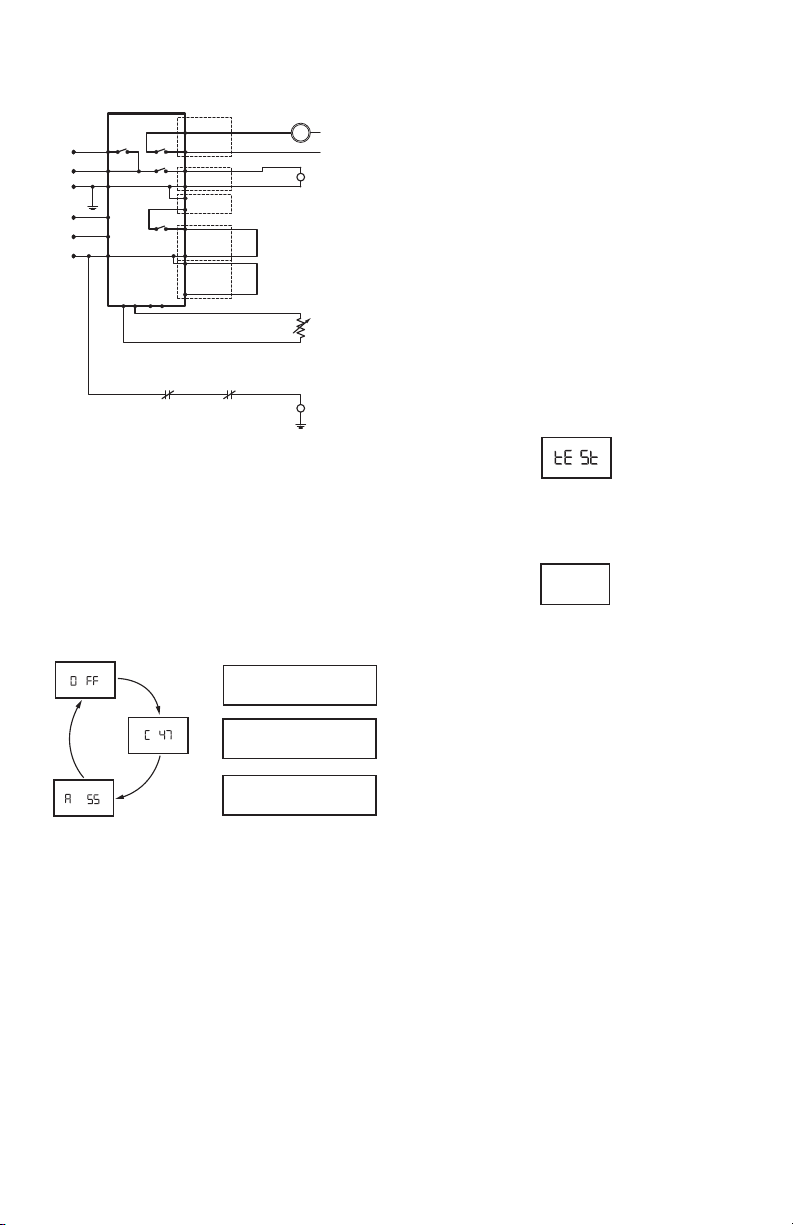
Fig. 8. Wiring diagram for simple timer applications.
CONFIGURATION
1. Connect power.
2. On power up the display will briefly flash the
software version of the DB7110U and then begin
cycling between the normal operating screens
showing the current mode and the values of the
two temperature sensors. Note that there is brief
startup delay following power up where compressor operation is prohibited.
Fig. 9.
The displayed coil and air temperature readings
can be very useful for optimizing and troubleshooting defrost performance.
3. There are several configurable options to optimize defrost performance. See “User Interface”
on page 7 for a detailed description of each
parameter/screen. Press the select (o) button
advance through the various screens and and
buttons to adjust the various parameters.
Table 4 below describes each parameter.
CHECKOUT
1. After the startup delay has expired, generate a
request for heat by shorting R to Y (and R to O if
configured as a “B” system, reversing valve energized in heating mode).
2. Verify the compressor, fan, and reversing valve (if
applicable) are energized.
3. Press and hold the button until “tESt” appears
on the display as shown below.
M37641
Fig. 10.
4. Verify the unit enters defrost mode
de Fr
M37642
Fig. 11.
The reversing valve will change states and the
aux heat will be energized. A few moments later
the fan will be turned off. If Reversing Delay is
enabled, the compressor will be turned off for
the selected time, and then turn back on to
reduce noise.
The DB7110U will remain in defrost for at least
one minute. After one minute has elapsed, the
DB7110U will exit defrost after the coil temperature has risen above the termination
temperature or after the selected defrost time,
whichever comes first.
Test mode can be terminated at any time by
pressing and holding the button again.
34-00032—01 4
Page 5

DB7110U UNIVERSAL HEAT PUMP DEFROST CONTROLLER
COMPATIBILITY CHART
Table 2. Compatibility Chart.
Amana C64301-1 C6431001
Arcoaire 32312-00 3232140
Armstrong 39840B001 44614-0001
44614-002 46257-001
47181-001 R46257-001
R46614-002 R47181-001
39840B002 37967B001
37967B002 R46K6701
R44614-001 R44614-002
Artesian 10321-00
Carrier 150-83-6A 621-xxxx
CES0110063-00 CES0110063-01
CES0110063-02A CES0130024-00
CES0130024-01 CES0130076
HK25SZ359A HK32EA001
HK32EA003 HK32EA007
HK32EA008 HK32FA003
HK32FA006
Coleman 3030A374 3030A364
3C30A374
Comfortmaker 1029-2 34332100
34332101
Evcon 9218-374
Fast 1093410
Goettl 305007
Goodman 1084-03-2022 1084-200D
20293901 B1226006
B1226008 LR4006 1
PCBDM101 PCBDM130
PCBDM133 PCBDM160
PCBDM101S PCBDM130S
Heil Quaker HQ1052727
Heil/Tempstar 1087952 1087953
1173636 CEPL130524-01
Honeywell ST74A1004 ST74A1020
ST74A1038 ST74A1053
ST74C1002
ICM DFORB24A21300 ICM300C
DFORB-AB1004 DFORF
DFOSP24A2 ICM301C
ICM302C ICM303C
ICM304 ICM307
ICM316 ICM317
ICM318 ICM319
ICM320 ICM321
ICM322 ICM323
W1001-4
ICP 1052757 1069364
Interthem 6208800
Table 2. Compatibility Chart. (Continued)
Lennox 100269-01 100269-02
100269-04 100269-05
11K7101 1507N170027
29M0101 29M0201
30W87 33G9501
34M6301 46K67
56M3701 68I2901
68J8401 78H6801
84W8801 86G1601
97M81 LB-101263A
LB-101263B 11K71
97M8101 30W8701
34M63 29M01
56M37 HPXB15
68I84 68I29
78H68
Nordyne 620880 621301A
621579B 621579C
624519A 624608
624626 624633
624644 624656
624700 917012
917178 917178A
920338 624644R
6246440 624633R
6246330
Ranco DT2
Rheem 47-102684-01 47-102684-02
47-102684-03 47-102684-04
47-102684-07 47-102684-08
47-102684-83 47-102685-01
47-102685-02 47-102685-03
47-102685-04 47-102685-05
47-102685-06 47-102685-84
47-21517-11 47-21517-13
47-21517-14 47-21517-16
47-21517-17 47-21517-18
47-21517-22 47-21517-23
47-21517-24 47-21517-82
47-21517-88 47-21517-92
47-21776-01 47-21776-06
47-21776-86 DDL-013002-0RH
DLL-013002-1RH DDL-0131020-1RH
DDL-017002-2RH DDL-017102-1RH
DDL-017702-1RH DDL-117702-3RH
DDL-122131-2RH 47-21517-12
47-21517-85 47-102685-87
47-102684-09 47-102685-07
47-21517-20
Robertshaw DT2-1000 TD-10
SnyderGeneral 1 395-329 CEBD430524-04B
5 34-00032—01
Page 6

DB7110U UNIVERSAL HEAT PUMP DEFROST CONTROLLER
Table 2. Compatibility Chart. (Continued)
Tempstar/ICP 1084-100 1084-83-1008
1087562
Therm-O Disc 26E-09
Trane 21C14501G18 21C1450127
21C1450136 21C1450137
21C1450138 21C1450142
21C1450144 21C1450145
21C1450153 21C1450154
21C1450155 21C1450160
21C14282G01 CNT01106
CNT01108 CNT01129
CNT01152 CNT01431
CNT01510 CNT01642
CNT01923 CNT01924
CNT01926 CNT02514
CNT02515 CNT02516
CNT02920 CNT02935
CNT03715 CNT03716
CNT04362 CNT04363
CNT04364 CNT04366
CNT04368 CNT04695
CNT05001 CNT05008
CNT05009 CNT05010
CNT05482 CNT05875
CNT1108 CNT01693
Weatherking 840-4-5548
White-Rodgers 840-4-5548 47D40-801
47D43-101 47D43-111
47D43-11102 47D43-811
90-621 47D01U-843
York 031-00872-001 031-00872-002
031-00872-002 031-00872-701
031-00872-702 031-00872-703
031-01222-000 031-01251-000
031-01268-000 031-01954-000
031-01975-000 031-09104-000
031-09170-000 331-01975-001
331-01975-102 331-09139-000
9218-3741 S1-03100872701
S1-03109170000 S1-33101954000
S1-33101975102
34-00032—01 6
Page 7

DB7110U UNIVERSAL HEAT PUMP DEFROST CONTROLLER
135
M37662
USER INTERFACE
The user interface consists of three buttons, two LED’s, and 4 7-segment digits. The two left digits generally
represent the category of what is being displayed while the two right digits represent the value or setting of the
category. The exception is in the event a value requires 3 digits such as a temperature higher than 99F as shown
below with two “termination temperature” values of 90F and 100F.
90
2
Fig. 12. Two example values of configuration option 2 (Termination Temperature).
The “o” button advances to the next screen while the and buttons are used to adjust the value of each
parameter.
Note that after one hour without a button press, the 7-segment display will turn off to save power. A button must
be pressed to turn the display on again.
Table 3. Status Screens.
Display Description
Current Fault(s) Present.
4
F
M37660
H 11
F
M37661
The configuration screens are numbered parameters where numbered parameter has a selectable value
according to the table below.
For example, would represent Parameter 1 (Defrost Enable Temperature) set to 35 (degF).
Right digits blank if there is no fault.
and to scroll through active faults.
Fault History
and to scroll through history.
Press an d hold for more than two seconds to clear all inactive faults.
2
1 00
M37659
Table 4. Configuration Screens.
Display Description Range Default
1 Defrost Enable Temperature
Coil temperature where defrost functionality is active.
2 Termination Temperature.
Coil temperature where defrost is terminated.
3 Defrost Cycle Time
Time the coil temperature is below the Defrost Enable
Temperature before a defrost is triggered if in timed mode
(no outdoor air sensor present).
4Short Cycle Delay Time
Minimum off time between compressor cycles.
5 Reversing Valve System Type
O = reversing valve energized in cool.
B = reversing valve energized in heat.
7 34-00032—01
30degF-36degF 35degF
70degF-100degF 70degF
30-120 minutes 30 minutes
0-5 minutes 3 minutes
O or B O
Page 8

DB7110U UNIVERSAL HEAT PUMP DEFROST CONTROLLER
Table 4. Configuration Screens. (Continued)
Display Description Range Default
6 Reverse Delay
Compressor off time when switching between heating and defrost
modes. Setting this to 0 will shorten the overall defrost time, but
may result in objectionably loud noises when entering/exiting
defrost (depending on compressor type).
7 Maximum Defrost Time
The maximum amount of time a defrost cycle can last. A defrost
cycle may be terminated earlier if the coil reaches the Termination
Temperature, but a defrost cycle should never last longer than this
time.
8 Aux Heat Lockout Temperature
W requests will be ignored if the outdoor temperature is higher
than this temperature. The Aux heat output will still function
normally during a defrost cycle regardless of this setting.
Do not set this temperature below the Compressor Lockout
Temperature or there will be a range of temperatures with no
heating operation.
9 Compressor Lockout Temperature
Y requests will be ignored if the outdoor temperature is lower than
this temperature.
Do not set this temperature above the Aux Heat Lockout
Temperature or there will be a range of temperatures with no
heating operation.
0-30 seconds 30 seconds
8-14 minutes 14 minutes
0degF-40degF No Lockout
-10degF-40degF No Lockout
(OF)
(OF)
Green LED: Indicates system power and operation.
Red LED: Indicates a fault is currently present and the user should inquire with the 7-segment display for more
information.
34-00032—01 8
Page 9

DB7110U UNIVERSAL HEAT PUMP DEFROST CONTROLLER
TROUBLESHOOTING AND MAINTENANCE
IMPORTANT
Due to the potential hazard of line voltage, only a trained experienced service technician should perform
the troubleshooting procedures.
This control contains no field-serviceable parts. Do not attempt to take it apart. Replace the entire control
if operation is not as described.
Table 5. Troubleshooting.
Condition Procedure Control Status Corrective Action
System does not
start with a call
for heat or cool
Compressor does
not stop when
the call for heat
or cool ends
System operates
in wrong mode,
heating when
cooling is
requested or vice
versa
Observe display for
current operational
mode.
Observe display for
current operational
mode.
Unplug Y wire from
control
Check O/B setup Control displays current
Display shows OFF • Verify call for heat or cool is present.
Control displays HEAT or
COOL but the system is
not operating.
Control displays DLY • The system is in a startup delay due
Control displays current
mode; OFF, HEAT, or
COOL.
Display shows OFF,
compressor turns OFF
Display shows OFF but
compressor remains ON
Display continues to show
shows HEAT or COOL
configuration:
• Check the wiring from thermostat and
indoor equipment
• Measure input terminals (W, Y, O) for
proper voltage.
• Verify cold weather compressor
lockout isn’t active. Adjust
“Compressor Lockout Temperature” if
necessary.
• Check wiring to outdoor equipment.
• Check contactor
• Measure output terminals for proper
voltage. WARN ING: fan terminals are
line voltage.
• Verify system pressure switches. The
onboard HPC and LPC terminals
must be shorted to run. Never bypass
protective pressure switches.
• Check coil sensor, the system will not
run without a coil sensor.
to short cycle protection, powerup, or
low voltage. Wait for the delay to
expire.
• If HEAT or COOL is shown after the
call ended, investigate thermostat
wiring.
• Investigate thermostat wiring to
ensure all wires are on the proper
terminals.
• Check the wiring between the control
and contactor.
• Check for a failed/stuck contactor.
•Unplug the COMPR wires and
measure voltage across the two
COMPR terminals. If they measure
24V while the display says OFF,
replace control.
• Replace the control.
• O means the control will be in
COOLING mode when there’s 24V on
the O terminal.
• B means the control will be in
HEATING mode when there’s 24V on
the O terminal. In most cases this will
only apply to Rheem units.
9 34-00032—01
Page 10

DB7110U UNIVERSAL HEAT PUMP DEFROST CONTROLLER
Table 5. Troubleshooting. (Continued)
Condition Procedure Control Status Corrective Action
System does not
defrost at all
System does not
defrost
completely
System defrosts
too much
No
Auxiliary/Emerg
ency Heat
Observe operational
mode while heating.
Observe defrost cycle Defrost starts too late. Too
Observe defrost cycle Defrost triggers too
Check configuration
parameters
Display shows COOL • O/b configured incorrectly. Verify
Display shows HEAT, but
no defrost is triggered.
much ice is built up before
starting a defrost cycle.
Defrost cycle ends too
soon. Not all the ice is
removed.
frequently, even with little
or no ice buildup.
Defrost cycle lasts too
long. Ice is melted long
before the cycle ends.
Active W request with no
Aux heat output
No Aux heat output during
defrost cycle
proper setting of O/b input for
reversing valve control. The control
won’t defrost if it “thinks” it’s in
cooling mode.
• Verify sensor placement and readings
are correct.
• Increase the “Enable Temperature” to
trigger defrost sooner. Defrost will
never be triggered if the coil
temperature does not fall below the
Enable Temperature. If the Enable
Temperature is too high, the system
may defrost when it’s not necessary.
• Verify sensor placement and readings
are correct.
• Increase the “Enable Temperature” to
trigger a defrost sooner.
• Lower the “Defrost Cycle Time” to
trigger a defrost sooner. Note this
parameter has no effect if an outdoor
air sensor is installed as the decision
would be made based on the
temperature difference between coil
and air.
• Verify sensor placement and readings
are correct.
• Increase the “Termination
Temperature” to allow the coil to get
hotter before a defrost cycle is
terminated.
• Increase the “Maximum Defrost
Time” to allow a defrost cycle to run
longer.
• Verify sensor placement and readings
are correct.
• Decrease the “Enable Temperature”
to force the coil to get colder before a
defrost is triggered. Increasing this
parameter too much can result in not
triggering a defrost at all. Verify coil
readings with respect to this
parameter.
• Increase the “Defrost Cycle Time” to
delay triggering a defrost. Note this
parameter has no effect if an outdoor
air sensor is installed.
• Verify sensor placement and readings
are correct.
• Decrease the “Termination
Temperature” to allow the defrost
cycle to end with a cooler coil
temperature.
• Decrease the “Maximum Defrost
Time” to force the defrost cycle to end
sooner.
• Verify warm weather aux heat lockout
isn’t active. Adjust “Aux Heat Lockout
Temperature” if necessary.
•Check wiring
•Replace control
•Check wiring
•Replace control
34-00032—01 10
Page 11

DB7110U UNIVERSAL HEAT PUMP DEFROST CONTROLLER
A
−−
M37655
A __
M37656
−−
C
M37657
Table 6. Fault Code Information.
Fault No. Description Corrective Action
1 Internal Communication Fault • Replace control
2 Internal Fault • Replace control
3 Low 24V • Measure 24V (R & C). There may be something in the
4 Corrupt Memory • Reset configuration options. Replace the control if the fault
5High Pressure Lockout – HPC
6 Low Pressure Lockout – LPC
7 High Pressure Cutout is currently
8 Low Pressure Cutout is currently
opened 3 times on a single
request.
opened 3 times on a single
request.
open
open
9 Coil Sensor Open Circuited • Check the sensor hasn’t become unplugged.
10 Coil Sensor Shorted • Check for pinched wires
11 Air Sensor Open Circuited • Check the sensor hasn’t become unplugged.
12 Air Sensor Shorted • Check for pinched wires
system loading the 24V transformer excessively. If voltage
is normal while the fault is currently active, replace the
control.
persists.
• Investigate refrigerant charge
• Check indoor coil for blockage
• Check outdoor coil for blockage
• Investigate refrigerant charge
• Investigate refrigerant charge
• Check indoor coil for blockage
• Check outdoor coil for blockage
• Investigate refrigerant charge
• Check sensor wiring
•Replace sensor
•Replace sensor
• Check sensor wiring
•Replace sensor
Note that this fault will only present itself if the sensor opens
after it has been detected. It will be cleared on a reset or power
cycle. Running without an air sensor causes the control to
operate in a timed defrost mode, which may be desired
operation.
•Replace sensor
Table 7. Sensor Diagnostics.
Display Description
Air sensor open circuit or unplugged
Air sensor shorted
Coil sensor open circuit or unplugged
__
C
Coil sensor shorted
M37658
11 34-00032—01
Page 12

DB7110U UNIVERSAL HEAT PUMP DEFROST CONTROLLER
Resideo Inc., 1985 Douglas Drive North,
www.resideo.com
©2018 Resideo Technologies, Inc. All rights reserved. Th e Honeywell Home trademark is used under license from Honeyw ell International Inc.
Golden Valley, MN 55422
34-00032—01 M.S. 12-18 | Printed in United States
 Loading...