

Page 1
CPZ100,
CPZZOO,
CP2201,
Honeywell
CRZ150,
CRZZOO,
CR2201
.
PUNCHED
CARD
SUBSYSTEMS
SERIES
400/600/
6000
HARDWARE
Page 2
CPZ100,
CPZZOO,
CPZZO1,
Honeywell
CRZ150,
CRZZOO,
CR2201
A
PUNCHED
CARD
SUBSYSTEMS
SERIES
400/
600/
6000
SUBJECT:
h
Information,
Functional
Characteristics,
Operating
Instructions,
and
Characteristics
of
Series
400/600/6000
Punched
Card
Subsystems.
SPECIAL
INSTRUCTIONS:
This
manualisan
updateofCPB-12288A,
dated
October
1966
and
revised
December
1967.
The
new
order
number
is
consistent
with
the
HIS
publications
numbering
system.
Changes
and
additions
are
indicated
by
bars;
deletions
are
indicated
by
asterisks.
DATE:
December
1973
/\
ORDER
NUMBER:
B037,
Rev.
0
Page 3
PREFACE
This
manual
furnishes
general
information
and
specific
reference
material
for
customer
executives,
system
analysts,
operators,
programmers,
and
others
interested
in
punched
card
subsystems
available
with
the
Series
400/
600/
6000
Information
Processing
Systems
and
the
DATANET
communications
systems.
The
first
section
will
satisfy
the
needs
of
those
who
want
only
a
highlight
of
what
the
subsystems
do.
Section
H
describes
in
detail
the
functional
capabilities
of
the
subsystems.
This
chapter
will
be
of
prime
interest
to
system
operators
and
furnishes
background
information
for
programmers.
Detailed
descriptions
of
operating
controls
are
found
in
Section
III.
The
individual
subsystems
and
the
unique
features
of
each
are
described
in
Appendix
A.
When
the
subsystems
are
being
used
with
a
Series
400
system,
the
term
"processing
system"
refers
to
the
Central
processor;
for
the
Series
600/6000,
the
term
refers
to
the
Input/
Output
Controller.
©1966,
1968, 1973,
Honeywell
Information
Systems
Inc.
File
No.:
1503,
1603,
1703
Page 4
CONTENTS
GENERAL
INFORMATION
Physical
Characteristics
.............................
. .
. .
Usewiththe
Series
600/6000... ...... . . . . ...
. .............
Use
with
the
Series
400
..................................
FUNCTIONAL
CHARACTERISTICS
Readers
...........>.....................................
Punches
................................................
Data
Media
........_......................................
ModesofOperation
...............l.........................
Readers..............
...............................
Punches
...................l.........................
Input/
Output
Signals
........................................
End
Data
Transfer
Signal
.................................
Terminate
Signal
......................................
Special
Interrupt
Signal
..................................
Status
Information
.....‘....................................
PriorityofStatus
............i.........................
Resetting
Status
........................................
Status
and
Substatus
Descriptions
.....p.i.........................
Channel
Ready
...............l.........................
Device
Busy
(R)
........................................
Attention
...........................................
Data
Alert
.................i.........................
Instruction
Rejected
.....................................
Load
Operation
Complete
(R)..
. ...........................
Intermediate
(P)
(CPZlOO
only)...I.........................
Channel
Busy
..............y..i.........................
Channel
Absent
..............a.........................
Channel
Alert
(R)
.............a.........................
Card
Reader
Instructions
.....................................
Operational
Instructions
....................‘.............
No
-Op
Instructions
.....................................
Card
Punch
Instructions
.....................................
Operational
Instructions
.................................
No
-Op
Instructions
.....................................
OPERATING
INSTRUCTIONS
CareofPunch
Cards
......................|.................
'
Handling
Cards
...............,...'.....................
Storing
Cards
........................................
Preparing
Cards
for
Loading
.............................
iii
Page
(ANN
cooooo-J-aqoacaoaoacncn
21
21
22
Page 5
Alert
Conditions
and
Corrective
Action
...............'...........
Operator
Maintenance
.....................................
CRZZOI
Card
Reader
......................................
Operator's
Control
Panel
................................
Card
Handling.
Mechanism.. . . . .......
. ...
...............
Setup
.............................................
Loading
Cards
.......‘................................
ConvertingtoAlternate-Size
Cards.. ...................
.
. .
Summary
of SettingUpProcedures
.........................
Unloading
Cards
.....................................
Normal
Operation
....................................
Shutdown..
......................
.......
CRZZOO/CRDISO
Card
Reader
......................
. . .
.......
Operator's
Control
Panel
...............................
Input/
Output
Area
Switches
.......‘.......................
Card
Handling
Mechanism
..............................
Setup.
.........-..........................
. . . ...'
.
Loading
Cards
.................................
. .....
UnloadingCards...............§
...............‘......
Shutdown
......................~....................
CPZlOO
Card
Punch...y....................................
Operator's
Control
Panel
...............................
Card
Handling
Mechanism
...............................
Setup
..................................‘.........
. .
Adding
Cards
.......................................
Removing
Cards
.....................»................
Emptying
the
Chad
Box
.................................
Shutdown..........................................
CPZZOO
Card
Punch
......................................
Operator's
Control
Panel
...............................
Card
Handling
Mechanism.. ...
. . .......................
Setup...........
..........
Adding
Cards
.............'..........................
RemovingCards..
.....
...............
Emptying
the
Chad
Box
.................................
Manually
ReturningtoOperate
State
.............
.......
.
Shutdown....
............
......
..........
CPZZOl
Card
Punch
...........................
.............
Operator'5Control
Panel
...............
. ...
. .
.
.
......
CardHandlingMechanism.
.....
Setup
..........
.......................
AddingCards
....................
Removing
Cards
......................................
Emptying
the
Chad
Box
.................................
Manually
ReturningtoOperate
State
..........
. ..;.. . . . . .
; . .
.Shutdown
........................
......
iv
Page 6
APPENDIXES
SUBSYSTEM
CHARACTERISTICS
CRZZOl
Card
Reader
.......................................
Data
Medium
.........................................
Speeds
and
Capacity.....................................
Data
Formats
....................................-. ...
Checking
.................................. .i........
Operating
Speeds
......................................
Timing
Considerations
.................................
~
Status
Returns
.......................................
Instructions
.......................................
CRZZOO/CRD15O
Card
Reader
................................
Data
Medium....»....................................
Speeds
and
Capacities
..................................
Data
Formats...
.....................................
.
Checking
..........................................
Operating
Speeds.......-....._..
........................
Timing
Considerations
.................................
Status
Returns
.......................................
Instructions
.........................................
CPZlOO
Card
Punch
.......................................
Data
Medium
.......................................
Speeds
and
Capacities
..................................
Data
Formats
.......................................
Substatus
States..
.
Checking
................
...............
Timing
Considerations
.................................
Status
Returns
......................................
Instructions
.........................................
CPZZOO
Card
Punch
............................‘...........
Data
Medium
.......................................
Speeds
and
Capacities
...................................
Data
Formats
. .-......................................
Subsystem
States
...........-...........................
Checking
...........................................
Timing
Considerations
.........I.........................
Status
Returns
...............T.........................
Instructions
.................i.........................
Page 7
CPZZOl
Card
Punch
.......................................
Data
Medium
.......................................
Speeds
and
Capacities
..................................
Data
Formats
_
.................................
,
......
Subsystem
States
.....................................
Checking
...........
'
................................
Timing
Considerations
.................................
Status
Returns
.........
_
..............................
Instructions
..........................
,
...............
CHARACTER
SET;
........................................
GLOSSARYo-----------_
.................................
INDEX
................................................
vi
Page 8
Figure
9°99?”
ILLUSTRATIONS
Blocking
Small
Decks
..................................
Riffle
Each
End
of
Cards
................................
CRZ201
Control
Panel
.................................
CRZZOl
Card
Reader
Mechanism
..........................
‘
Track
Jam
Release
Mechanism
(Opened)
,,,,,,,,,,,,,,,,,,,,,
-
Stacker
Jam
Release
Mechanism
...........................
Card
RailinPlace
for
Reading
51-Column
Cards
...............
Card
Bumper
.......................................
CRZZOO
Control
Panel
.................................
CRZZOO
Input/
Output
Area
Switches
..........................
CRZZOO
Card
Reader
Mechanism
...........................
Adding
CardstoEmpty
HOpper
.............................
Inserting
First
CardinFeed
Throat
.........................
Adding
Cards
During
Feed
Operations
........................
Removing
Cards
During
Feed
Operations
......................
Blocking
CardsinStorage
Tray
............................
Removing
All
Cards
from
Stacker
...............i...........
CPZlOO
Control
Panel
.................................
CPZlOO
Card
Punch
Mechanism
...........................
CPZZOO
Control
Panel
.................................
CPZZOO
Card
Punch
Feed
Mechanism
(Left
Side
View)
............
CPZ201
Control
Panel
..................................
CPZZOI
Card
Feed
Mechanism
...........................
CRZ201
Card
Reader
Subsystem
...........................
CRZZOO/
CRD150
Card
Reader
Subsystem
.....................
CPZlOO
Card
Punch
Subsystem
...........
'
................
CPZZOO
Card
Punch
Subsystem
...........................
CPZZOI
Card
Punch
Subsystem
...........................
vii
54
59
62
68
73
'75
79
.83
Page 9

Page 10
1.
GENERAL
INFORMATION
The
Honeywell
Series400/
600/
6000
Information
Processing
Systems
are designed
to
give
the
user
versatility
of
operation
in
card
subsystem
equipment.
Card
reading
equipment
reads
information
punched
into
tabulating
cards
in
alphanumeric
or
binary
modes
and
feeds
it
into
the
core
store
of
the
central
processor
for
processing
or
storage.
‘The
user
has
a
choice
of
reading
speeds
from
900
to
1200
cards
per
minute
to
meet
his
requirements.
~
Card
readers
are
designed
to:
o
Handle
either
round-1
or
square-cornered
cards,
intermixed.
0'
Read
cards
punched
in
alphanumeric.
(binary-coded
decimal,
or
Hollerith)
and
12-row
binary,
formats.
0
Operate
simultaneously
with
central
processor
computation
and
other
input/
output
operations.
'
o
Readatvariable
speeds
(asynchronous).
o
Read
cards
serially,
column
by
column,
by
means
of
photocells
which
provide
reliable
and
accurate
reading
of
data
in
either
continuous
or
demand-type
operations.
0
Check
card
timing
and
synchronization,
proper
card
feeding
and
reading,
empty
homer,
and
full
stacker.
0
Check
for
the
presenceofinvalid
characters.
Card
punching
equipment
permits
information
from
the
central
processor
to
be
recorded
directly
on
cards
under
control
ofastored
program.
Punching
speeds
from
100to300
cards
per
minute
are
available.
Card
punches
are
designed
to:
0
Punch
cardsinalphanumeric
or
12-row
binary
formats.
0
Operate
simultaneously
with
central
processor
computation
and
other
peripheral
subsystems.
0
Punch
cards
rowbyrow,80columnsata
time.
0
Check
card
feeding
0
Check
punching
accuracybya
read-after-punch
hole
count.
-1-
Page 11
PHYSICAL
CHARACTERISTICS
The
punched
card
subsystems,
packaged
as
single,
freestanding
units,
are
on-line
devices,
each
consisting
of
a
card
handling
mechanism,
control
electronics,
and
a
power
supply.
Operator’s
control
panels
display
a
full
array
of
controls
and
indicators
for
observing
and
controlling
the
operation
of
the
subsystems.
The
power
supply
is
adequately
fused
against
overloads
and
provides
and
regulates
the
necessary
a.c.
and
d.c.
voltages
for
the
card
handling
mechanism
and
the
control
electronics.
The
control
electronics
interpret
and
transmit
to
and
from
the
processing
system
the
data
read
from
or
punched
into
cards
and
generate
and
transmit
timing
signals
and
information
on
the
operating
condition
of
the
subsystem.
USE
WITH
THE
SERIES
600/6000
Whenever
the
subsystem
operates
within
a
multiprogramming
environment,
its
operation
must
be
coordinated
to
mesh
efficiently
and
simultaneously
with
that of
other
peripheral
equipment
in
the
system.
The
General
Input/
Output
Supervisor
(GIOS)
program,
avail-
able
with
the
Series
600/
6000
systems,
does
this
for
the
programmer-
It
handles
the
details
that
arise
from
supervising
the
activities
and
status
of
many
peripherals
and
makes
the
most
efficient
use
of
them
in
conjunction
with
the
valuable
time
of
the
process-
ing
unit.
Whenever
use
of
the
subsystem
is
required,
GIOS
communicates
with
the Input/
Output
Controller
(ICC)
by
means
of
a
connect
instruction.
If
the
subsystem
is
busy
when
the
'
output
request
is
made,
GEIOS
queues
the
request
until
the
subsystem
becomes
ready.
When
the
subsystem
has
accepted
the
instruction
and
received
all
the
information
necessary
to
initiate
data
acceptance
and
punching
or
reading,
the
connect
sequence
ends
and
the
IOC.
data
service
sequence
begins.
This
sequence
controls
the
transfer
of
information
to
the
subsystem.
V
When
operation
stops,
either
because
of
a
normal
termination
or
because
an
alert
condition
occurred,
the
IOC
places
the
status
and
substatus
of
the
subsystem
in
the
proper
queue
and
sends
a
program
interrupt
signal
to
the
store
controller.
6108,
in
turn,
checks
each
queue
'
entry
to
be
sure
that
the
peripheral
operation
was
completed
free
of
errors.
If
it
was
not,
the
prOper
recovery
routines
are
called
in.
6108
also
returns
status
and
substatus
information
to
the
program
whenever
it
requests
it.
With
GIOS
efficiently
assuming
the
burden
of
responsibility
for
directing
peripheral
operations,
the
programmer
is
relieved
of
much
detailed
programming.
Programming
information
on
the
use
of
the
subsystem
with
the
Series
600/6000
is
containedinSeries
6000/
600
General
File
and
Record
Control
stem,
BN85,
and
Series
60007300
Em?
Macro
Esemfijl
firogram,
ENE.
.
.
l.,
Page 12
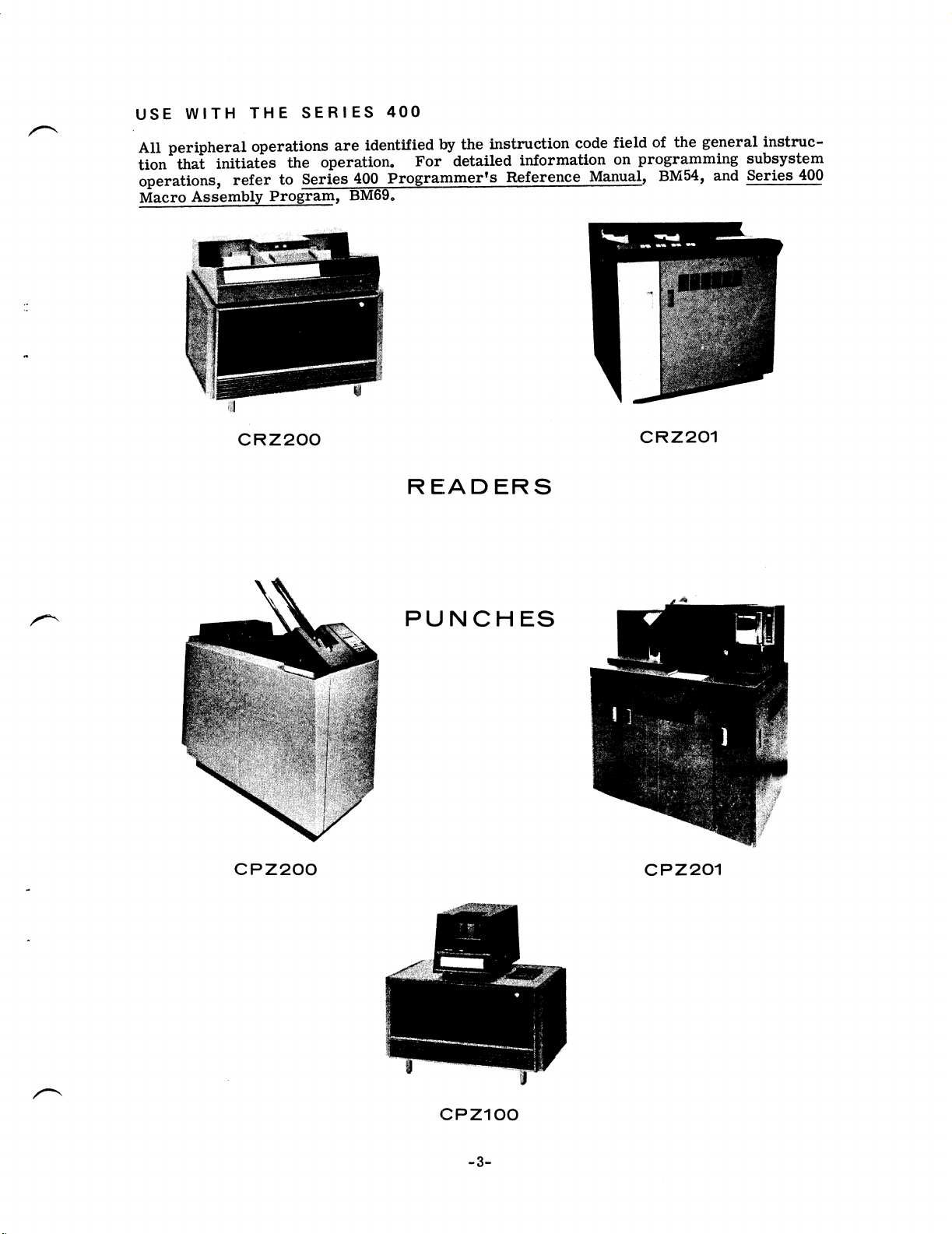
USE
WITH
THE
SERIES
400
A
~
All
peripheral
operations
are
identified
by
the
instruction
code
field
of
the
general
instruc-
tion
that
initiates
the
operation.
For
detailed
information
on
programming
subsystem
operations,
refer
to
Series
400
Programmer's
Reference
Manual,
BM54,
and
Series
400
Macro
Assemblx
Program,
BM69.
CRZZOO
CR2201
R
EIADERS
r“
P
U N
C
H
ES
CP2
200
CP2
201
/'\
'
CPZ1OO
-3-
Page 13

Page 14
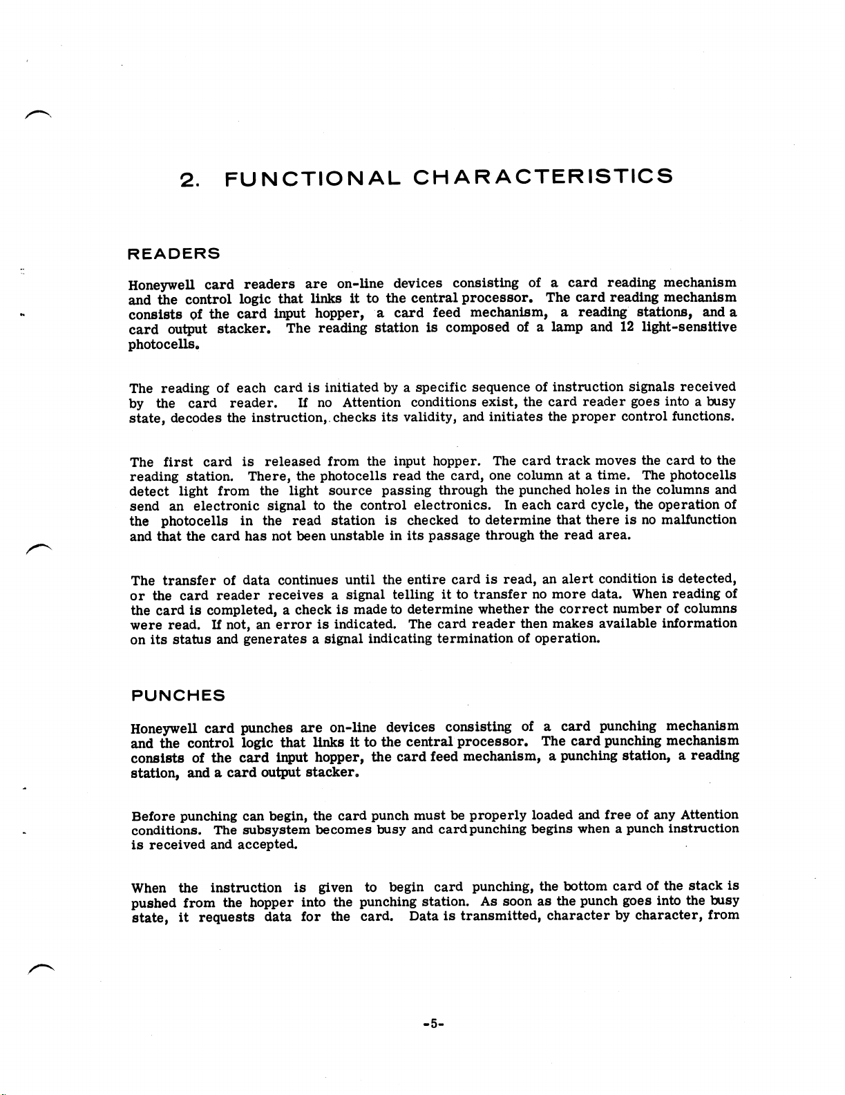
2.
FUNCTIONAL
CHARACTERISTICS
READERS
Honeywell
card
readers
are
on-line
devices
consisting
of
a
card
reading
mechanism
and
the
control
logic
that
links
it
to
the
central
processor.
The
card
reading
mechanism
consists
of
the
card
input
hopper,
‘a
card
feed
mechanism,
a
reading
stations,
and
a
card
output
stacker.
The
reading
station
is
composed
of
a
lamp
and
12
light-sensitive
photocells.
The
reading
of
each
cardisinitiatedbya
specific
sequenceofinstruction
signals
received
by
the
card
reader.
If
no
Attention
conditions
exist,
the
card
reader
goes
intoabusy
state,
decodes
the
instruction,.checks
its
validity,
and
initiates
the
prOper.
control
functions.
The
first
card
is
released
from
the
input
hopper.
The
card
track
moves
the
Cardtothe
reading
station.
There,
the
photocells
read
the
card,
one
columnata
time.
The
photocells
detect
light
from
the
light
source
passing
through
the
punched
holesinthe
columns
and
send
an
electronic
signaltothe
control
electronics.
In
each
card
cycle,
the
Operation
of
the
photocells
in
the
read
station
is
checkedtodetermine
that
thereisno malfunction
and
that
the
card
has
not
been
unstableinits
passage
through
the
read
area.
The
transfer
of
data
continues
until
the
entire
card
is
read,
an
alert
condition
is
detected,
or
the
card
reader
receives
a
signal
telling
it
to
transfer
no
more
data.
When
reading
of
the
card
is
completed,
a
check
is
made
to
determine
whether
the
correct
number
of
columns
were
read.
If
not,
an
error
is
indicated.
The
card
reader
then
makes
available
information
on
its
status
and
generates
a
signal
indicating
termination
of
operation.
PUNCHES
Honeywell
card
punches
are
on-line
devices
consisting
of
a
card
punching
mechanism
and
the
control
logic
that
links
it
to
the
central
processor.
The
card
punching
mechanism
consists
of
the
card
input
hopper,
the
card
feed
mechanism,
a
punching
station,
a
reading
station,
and
a
card
output
stacker.
Before
punching
can
begin,
the
card
punch
mustbeproperly
loaded
and
freeofany
Attention
conditions.
The
subsystem
becomes
busy
and
card
punching
begins
whenapunch
instruction
is
received
and
accepted.
When
the
instruction
is
given
to
begin
card
punching,
the
bottom
card
of
the
stack
is
pushed
from
the
hopper
into
the
punching
station.
As
soon
as
the
punch
goes
into
the
busy
state,
it
requests
data
for
the
card.
Data
is
transmitted,
character
by
character,
from
-5-
Page 15
the
processing
system
to
the
buffer
of
the
punch’s
controller.
The
parity
of
each
character
is
checked
as
it
is
received.
If
the
instruction
requests
the
data
to
be
punched
in
the
Hollerith
code,
the
code
is
converted
by
the
controller
before
the
data
enters
the
buffer.
The
80
punching
dies
punch
the
card,
a
row
ata
time.
The
card
then
moves
into
the
reading
station,
where
80
wire
brushes
read
it
by
sensing
the
presence
or
absence
of
holes.
From
the
reading
station,
the
card
is
moved
to
the
output
stacker.
DATA
MEDIA
The
subsystems
accept
and
punch
or
read
data
into
or
from
punched
cards
in
a
variety
of
intermixed
card
stocks.
The
mechanism
of
the
subsystem
handles
cards
so
as
to
produce
the
least
possible
wear
both
to
the
cards
and
to
the
subsystem
itself.
Cards
should
meet
the
basic
requirements
specified
for
their
use
with
most
electronic
and
tabulating
equipment
in
order
to
provide
the
greatest
possible
amount
of
service.
The
subsystems
also
handle
cards
exposed
to
a
wide
range
of
temperature
and
humidity
conditions,
provided
the
cards
are
first
given
a
reconditioning
period.
MODES
OF
OPERATION'
Readers
ALPHANUMERIC
MODE.
The
contents
of
each
card
column
punched
in
the
Hollerith
format
are
converted
to
the
equivalent
6-bit
character
and
transmitted
with
an
odd
parity
bit.
In
addition,
a
check
is
made
to
see
that
the
punches
in
each
column
represent
a
valid
character
of
the
character
set.
(See
the
Appendix
B
of
this
manual
for
the
character
set
and
the
corresponding
punches
in
the
Hollerith
format.)
'
BINARY
MODE.
Data
punched
into
the
top
halfofeach
column
(row
12-row3)is
transmitted
as
the
first
character,
supplemented
by
an
odd
parity
bit.
Data
read
from
the
lower
half
of
the
column
(row
4-row9)is
transmittedasthe
second
character.
MIXED
MODE.
When
the
card
readerisoperatinginthe
mixed
mode,itis
readingadeck
composed
of
both
alphanumeric
and
binary
cards.
As
each
card
enters
the
reader,
column
1isexamined
to
determine
which
type
the
cardisand
thus,
how
the
dataistobehandled.
If
the
‘7'
and
“9"
of
column1are
punched,
regardlessofwhat
other
punches
occurinthe
column,
the
card
is
read
in
the
binary
mode.Ifeitherorbothofthese
two
punches
are
missing,
the
card
is
readinthe
alphanumeric
mode.
In
either
case,
the
full80columns
of
card
information
are
transmitted,
including
column
1.
Since
there
are no
alphanumeric
characters
represented
by
both
the7and9punches,
either
withorwithout
other
punches,
the
card
reader
cannot
accidentally
misinterpretastandard
Hollerith
punch
configuration
in
column1for
the
special
identifying7and9punchesofa
binary
card.
Punches
OD
Two
6-bit
binary
characters
are
punched
into
each
card
column.
The
first
character
goes
into
card
rows
12-3
(row
12
contains
the
most-significant
bit).
The
-3-
Page 16
second
character
is
punched
into
card
rows
4-9
(row
4
is
the
most-significant
bit).
The
third
and
fourth
characters
are
punchedl
in
column
2,
etc.
ALPHANUMERIC
MODE.
Each
6-bit
data
character
received
is
converted
into
Hollerith
code
and
punched
into
a
single
card
column.
The
character
set
and
the
corresponding
punches
in
the
alphanumeric
format
are
given
in
Appendix
B
of
this
manual.
EDITED
ALPHANUMERIC
MODE.
This
mode
of
operation
is
identical
to
the
alphanumeric
mode,
but
with
the
additional
feature
of
allowing
the
punch
to
delete
any
Ignore
characters
(octal
17)
which
it
may
receive.
Whenever
an
Ignore
character
is
deleted,
the
next
valid
character
received
is
punched
with
no
blank
column
intervening.
INPUT/OUTPUT
SIGNALS
Instructions
transmitted
to
the
subsystem
and
data
transmitted
to
or
received
from
the
subsystem
are
accompanied
by
signals
that
help
time
operations,
trigger
operations,
and
identify
information.
Some
signals
function
automatically,
while
others
can
be
accessed
or
caused
by
programmers
or
operators.
Those
signals
of
direct
concern
to
users
are:
EndData
Transfer
Terminate
Special
Interrupt
End
Data
Transfer
Signal
The
processing
system
transmits
the
End
Data
Transfer
signal
to
the
subsystem
to
indicate
that
no
more
data
is
to
be
transferred.
A
list
pointer
word
overflow
causes
this
signal
in
a
Series
400
system.
When
the
subsystem
receives
the
signal,
or
an
error
condition
is
detected,
data
transfer
is
terminated
for
the
remainder
of
the
card
operation
time.
The
two
error
conditions
that
cause
this
are
the
Attention,
Read
Alert,
and
the
Data
Alert,
Transfer
Timing
Alert,
conditions.
Both
are
defined
under
“Status,”
below.
Note
that
the
subsystem
remains
in
the
Channel
Busy
state
for
the
entire
operation
time.
Terminate
Signal
The
subsystem
transmits
the
Terminate
signal
to
the
processing
system
to
indicate
that
the
Channel
Busy
condition
was
terminated
for
one
of
the
following
reasons:
1.
Processingofa
cardiscomplete.
2.
A
card
jam
was
detected.
3.
A
data
alertisdetected.
-7-
Page 17

The
status
information
transmitted
with
the
Terminate
signal
identifies
the
specific
type
of
termination.
’
Special
Interrupt
Signal
The
subsystem
transmits
the
Special
Interrupt
signal
to
the
processing
system
to
call
attention
to
a
change
in
the
operating
state
of
the
subsystem.
The
signal
means
that
the
subsystem
was
manually
cleared
from
the
Attention
status.
STATUS
INFORMATION
The
punched
card
subsystem
transmits
status
information
about
its
Operating
condition
to
the
processing
system.
The
status
tells
the
processing
system
when
the
subsystem
is
ready
to
accept
an
instruction
or
is
busy,
whether
an
instruction
was
successfully
executed,
when
error
conditions
have
occurred,
etc.
Status
information
can
be
placed
in
core
store
and
interrogated
by
the
program.
When
used
in
this
way
by
the
program
or
Operating
system,
the
status
permits
detecting
and
attempting
to
recover
from
certain
error
conditions
under
program
control.
For
conditions
that
require
operator
intervention,
status
enables
the
program
or
operating
system
to
give
specific
instructions
to
the
operator
for
correcting
inoperable
conditions.
There
are
two
types
of
status
information--the
major
status
and
the
substatus.
Major
status
indicates
the
general
category
of
the
condition.
For
some
major
statuses,
there
are
substatuses
that
indicate
more
specific
reasons
for
the
existence
of
the
major
status.
In
the
following
discussions
of
major
status
and
substatus,
codes
are
interpreted
as
follows:
Bit
positions
———>
232221
2°
Major
Status
Code—p
O 0
0
0
Bit
positions
—————>25
242a22
2"1
2°
Substatus
Code—90
0
x
x
1
x
A
bit
shown
as
“0”
must
always
be
zero.Abit
shownas“x”
canbeeither
oneorzero.
A
l-bit
identifies
the
existing
condition.
The
patternofx’s,
1’s,
and
0’s
indicates
which
substatuses
can
occur
together.
.
The
major
statuses
that
may
be
encounteredbya
punched
card
subsystem
are
described
on
the
following
pages.
The
list
below
shows
the
4-bit
configuration
for
each
major
status
possible.
The
exact
statuses
returnedbyaparticular
subsystem
are
giveninthe
subsystem
descriptionsinAppendix
A.
-8-
Page 18
/A\
Readers
and
Punches
Channel
Ready
0000
Attention
.
0010
Data
Alert
0011
Instruction
Rejected
0101
Channel
Busy
1000
Channel
Absent*
1001
ReadersOnly
Device
Busy
0001
Load
Operation
Complete
0111
Channel
Alert*
1010
CPZlOO
Punch
Only
Intermediate
0110
*NOTE:
Channel
Absent
and
Channel
Alert
are
generatedbythe
I/O
channelofthe
G-400
Series.
~
Major
status
always
existsoncertain
electrical
linesinthe
subsystem.
This
status
changes
only
on
initiation
or
termination
of
an
instruction.
Substatus
existsinthe
subsystem
only
during
initiation
and
after
terminationofan
instruction.
Priority
of
Status
When
two
or
more
major
statuses
exist
simultaneously,
the
subsystem
sends
the
higher
priority
status.
For
these
subsystems,
major
statuses
rankasfollows
(highest
priority
listed
first):
.
'
Channel
Absent
Channel
Alert
Attention*
(Card
Jam
Only)
Instruction
Rejected
Data
Alert
Intermediate
Attention"
(Other
than
Card
Jam)
Load
Operation
Complete*
Device
Busy*
’
Channel
Busy
Channel
Ready
Instruction
Rejected
is
never
stored
in
the
subsystem.
Thisisa
transient
condition
that
is
reflected
to
the
processing
system
only
in
responsetothe
instruction
being
rejected.
Reflection
of
the
Instruction
Rejected
major
status
never
affects
the
status
currently
stored.
‘
*Attention
inhibits
existenceofLoad
Operation
Complete
and
Device
Busy.
-9-
Page 19
Resetting
Status
Receipt
of
any
valid
instruction
by
the
subsystem
(except
Request
Status)
resets
all
existing
program-resettable
statuses
within
the
subsystem
except
certain
conditions
that
still
exist.
Channel
Ready
is
not
reset,
but
exists
as
an
all-zero
condition
when
all
other
major
statuses
are
reset
to
zero.
Methods
of
resetting
status
are
indicated
below:
'
Data
Alert
Instruction
Rejected
Reset
by
initiation
of
any
valid
instruction
Load
Operation
Complete
except
Request
Status
Channel
Alert
Device
Busy
Reset
automatically,
on
instruction
initiation,
Channel
Busy
'
provided
causative
condition
no
longer
exists
Intermediate
Channel
Ready
Not
reset
Attention
Reset
by
operator
intervention
Channel
Absent
_
Reset
by
putting
subsystem
on
line
Only
one
program-resettable
major
status
is
stored
at
any
one
time.
If
a
program-resettable
condition
exists
with
a
lower
priority
nonresettable
status,
the
program
resets
the
higher
priority
status.
The
code
of
the
lower
priority
status
is
then
available
to
the
processing
system.
STATUS
AND SUBSTATUS
DESCRIPTIONS
In
the
detailed
descriptions
which
follow,
the
symbol
(R)
indicates
a
condition
which
occurs
only
on
the
readers.
(P)
indicates
a
condition
which
occurs
only
on
the
punches.
Note
that
the
substatus
configuration
for
those
major
statuses
without
substatuses
is
always
000000.
Channel
Ready
The
Channel
Ready
major
status
indicates
that
execution
of
the
preceding
instruction,
if
there
was
one,
was
error-free
and
the
subsystem
is
ready
and
available
to
accept
a
new
instruction.
NOTE:
A
punch
subsystem
may
be
not-busy
and
still
not
be
in
the
ready
state.
Device
Busy
(R)
The
Device
Busy
status
is
transmitted
in
response
to
a
Request
Status
or
Reset
Status
instruction
to
indicate
that
a
card
is
in
transit
to
the
read
station.
The
status
is
sent
when
two
Feed
instructions
or
two
Stack
instructions
are
given
in
succession.
-10-
Page 20
Attention
The
subsystem
sends
the
Attention
major
status
to
indicate
that
an
inoperable
condition
exists
that
requires
operator
correction.
The
subsystem
rejects
subsequent
instructions,
with
one
exception,
with
this
return
until
the
condition
is
corrected
and
the
logic
is
manually
reset.
However,
if
the
Attention
status
transmitted
at
terminate
time
was
caused
by
a
Hopper/
Stacker
Alert,
a
Manual
Halt,
the
Last-Batch,
condition,
or
a
Read
Alert
(all
described
below),
the
reader
can
accept
a
Stack
instruction
and
stack
the
card
for
which
the
respective
Terminate
signal
was
given.
One
or
more
substatuses
always
occur
with
the
Attention
major
status.
Unless
otherwise
noted
in
the
descriptions
below,
when
an
Attention
condition
is
detected
during
the
Channel
Busy
condition,
the
busy
stateisnot
terminated
until
normal
termination
time.
This
allows
cardsintransittobe
processed
before
feeding
halts.
The
substatuses
that
can
occur
with
the
Attention
major
status
are
described
below.
The
binary
code
for
each
substatusisshowninparentheses.
HOPPER/STACKER
ALERT
(xxxxxl)--Occurs
when
the
input
hopper
is
emptyorthe
output
stacker
is
full.
(See.
Appendix
A
for
additional
conditions
which
may
cause
this
conditiononthe
CRZZOI
Reader.)
MANUAL
HALT
(xxxxlx)--Occurs
when:
1.
The
MANUAL
HALT.
pushbutton
on
the
operator’s
control
panelisactuated.
2.
Poweristurnedonby
the
POWER
ON
pushbutton.
3.
The
field
engineer
goes
from
the
off-line
test
modetothe
on-line
mode.
4.
(P)
Blank
cards
have
not
been
loaded
into
the
prepunch
stations.
LAST
BATCH
(R)
(xxx1x1)--Occurs
when
the
input
hopper
goes
empty
while
the
LAST
BATCH
controlisin
theonstate.
FEED
ALERT
(OxlxnguOccurs
whenacard
failstofeed
from
the
hopper
into
the
card
trackinresponsetoa
FeedorPunch
instruction.
CARD
JAM
(x1xxxx)--Occurs
when
the
progress
ofacardonthe
card
track
becomes
impeded
to
the
poinTthat card
feeding
cannotbesuccessfully
completed.Ifthe
subsystem
is
in
the
Channel
Busy
state
at
this
time,
the
subsystem
interrupts
the
current
Operation
and
terminates
the
instruction
being:
executed.
If
the
subsystem
was
notinthe
Channel
Busy
stateattimeofdetecting
the
card
jam,
the
subsystem
revertstothe
Attention
condition
and
rejects
further
instructions
with
this
status.
On
detection
of
a
card
jam,
the
electrical
power
starts
cycling
down.
Note
that
Card
Jam
overrides
any
other
existing
statusinthe
subsystem.
-11-
Page 21
If
the
processing
system
recognized
the
last
data
character
sent
from
a
reader,
the
subsystem
sends
a
Terminate
signal.
If
the
card
reader
has
sent
a
character
that
was
not
recognized,
no
Terminate
signal
is
sent.
READ
ALERT
(R)
(1x0xxx)--Occurs
upon
failure
of
any
card
check
(light
check,
dark
check,
column
strobe
count
check,
or
internal
parity
check)
made
at
the
read
station
during
card
reading
time.
SNEAK
FEED
(R)
(lexxx)--Occurs
when
a
card
is
fed
without
the
reader
having
received
an
instruction
to
feed.
No
data
is
transmitted
from
the
card.
No
Terminate
signal
is
sent.
CHAD
BOX
FULL
(P)
(0xx1xx)--Occurs
when
too
much
chad
has
accumulated
and
chad
box
must
be
emptied
before
punching
can
continue,
or
the
chad
box
is
not
present.
Data
Alert
The
subsystem
returns
the
Data
Alert
major
status
to
the
processing
system
to
indicate
that
some
type
of
error
or
alert
condition
was
detected
during
the
processing
of
a
card.
One
or
more
of
the
substatuses
always
occur
with
Data
Alert.
Occurrence
of
a
Data
Alert
condition
does
not
cause
termination
of
the
Channel
Busy
condition.
The
operation
in
progress
is
allowed
to
come
to
its
normal
termination.
The
substatuses
that
can
occur
with
Data
Alert
are
described
below:
TRANSFER
TIMING
ALERT
(R)
(000001)--Occurs
when
the
card
reader
data
buffers
become
filled,because
the
processing
system
has
failed
to
recognize
a
transmitted
character,
or
it
can
mean
that
the
processing
system
has
not
accepted
all
characters
read
from
a
card
by
the
time
the
card
clears
the
read
station.
Transfer
of
data
to
the
processing
system
is
immediately
stopped,
but
the
Channel
Busy
state
is
not
terminated
until
card
reading
is
completed
and
all
checks
are
made.
TRANSFER
TIMING
ALERT
(P)
(000xx1)--Occurs
whenever
the
time
arrives
for
the
punch
dies
to
be
actuated
but
the
punch
has
not
yet
received
all
of
the
required
data.
The
Operation
terminates.
VALIDITY
ALERT
(R)
(000x10)--Occurs
when
the
subsystem
detects
an
invalid
character
while
reading
an
alphanumeric
card.
The
subsystem
sends
an
Ignore
character
(octal
17)
in
place
of
the
invalid
configuration
from
the
card
column.
Reading
continues
until
normal
termination
time;
then
the
subsystem
sends
the
substatus
and
the
Terminate
signal.
TRANSMISSION
PARITY
ALERT
(P)
(000x1x)--Occurs
whenever
a
parity
error
is
detected
on
the
data
characters
received
for
punching.
Operation
terminates.
-12-
Page 22
DUAL
READ
ALERT
(R)
(0001x0)--Occurs
when
the
two
outputs
of
the
dual
read
head
do
not
meet
the
compare
test
for
a
card
column.
In
the
binary
mode
of
Operation,
the
subsystem
transmits
two
Ignore
characters
in
place
of
thetwo
characters
in
the
card
column.
In
the
alphanumeric
mode,
the
subsystem
transmits
one
Ignore
character
in
place
of
the
Hollerith
character
in
the
card
column.
The
subsystem
continues
reading
the
card
and
sends
the
Data
Alert
at
normal
termination
time.
PUNCH
ALERT
(P)
(OOlex)--Occurs
whenever
the
row
parity
accumulated
from
the
read
Ration
does
not
agree
with
that
previously
established
when
the
data
entered
the
card
image
buffer
in
the
controller.
After
the
Punch
Alert
substatus
and
Data
Alert
status
information
has
been
transmitted,
the
punch
sendsaTerminate
signal.
Since
the
punch
check
is
made
by
the
read
head
while
the
following
cardisbeing
punched,
a
punch
alert,
if
there
is
one,
concerns
not
the
card
just
punched,
but
the
card
just
read
and
entering
the
stacker.
The
last
card
tobepunchedatany
time,
regardlessofwhetheritis
the
last
data
cardora
blank
card
following
the
data
deck,
is
automatically
transported
through
the
read
station
and
punch-checked.
The
only
indicationofa
punch
alertonthis
cardisthe
illumination
of
the
PUNCH
ALERT
indicatoron
the
operator’s
controlpanel.
Whenablank
cardisprovided
by
the
program,apunch
alert
on
the
last
data
cardisindicatedbyprogrammed
typeout;
but
a
punch
alert
on
the
blank
card
is
indicated
onlybythe
PUNCH
ALERT
indicator.
NO
READ
INSTRUCTION
(R)
(001000)--Occurs
whenacardisfedasthe
resultofa
Feed
instruction
and
enters
the
read
station
before
aRead
instructionisreceivedbythe
subsystem.
No
dataistransmitted
from
thecard.
Instruction
Rejected
The
subsystem
transmits
the
Instruction
Rejected
major
statustoindicate
that
the
received
instructionisbeing
rejected.
Oneofthe
following
substatuses
occuronthe
readertoshow
why
the
instructionisrejected.
Note
that
only
one
substatus
can
occuratany
time.
No
substatus
occursonthe
punch
subsystems.
INVALID
OPERATION
COD/E
(R)
(000001)--Occurs
when
the
operation
codeisnot
recog-
nizable
for
any
reason,
includingaparity
error.
NO
CARD
COMMITTED
(R)
(000010)--Occurs
whenaStack
instructionisreceived
when
no
card
isintransittothe
stacker.
The
substatusisreflected
onlytoStack
instructions.
LATE
READ
INSTRUCTION
(R)
(000100)--Occurs
when
a
Read
instruction
is.received
after
the
card
has
entered
the
read
station.
This
substatusisreflected
onlytoRead
instructions.
-13-
Page 23
Load
Operation
Complete
(R)
The
reader
returns
the
Load
Operation
Complete
major
status
to
indicate
the
termination
of
a
successful
program
load
operation.
Intermediate
(P)
(CPZ1OO
only)
The
Intermediate
major
status
indicates
that
the
punch,
although
not
currently
engaged
in
data
transfer
or
in
actual
punching,
is
not
at
the
end
of
the
card.
It
has
finished
punching
a
row
(other
than
the
9-row)
without
encountering
an
alert
condition
and
is
awaiting
the
instruction
to
punch
the
next
row
of
data.
This
status
is
always
automatically
set
between
rows.
Channel
Busy
The
subsystem
transmits
the
Channel
Busy
major
status
to
indicate
that
it
is
processing
a
card
and
receiving
or
transmitting
data.
Channel
Absent
The
1/0
channel
circuitry
of
the
Series
400
generates
the
Channel
Absent
major
status
to
indicate
that
the
processing
system
cannot
communicate
with
the
subsystem.
Reasons
can
be
that
the
subsystem
is
disconnected,
without
power,
or
absent.
Channel
Alert
(R)
The
1/0
channel
circuitry
of
the
Series
400
generates
the
Channel
Alert
major
status
to
indicate
that
during
the
card
reading
operation
just
ended,
the
processing
system
received
a
character
with
incorrect
parity.
CARD
READER
INSTRUCTIONS
The
General
Electric
card
readers
are
capable
of
executing
both
Operational
and
non-
operational
instructions.
A
6-bit
operation
code
in
the
instruction
informs
the
reader
of
the
operationtobe
performed.
Operation
Code
Function
000000
Sends
the
code
for
the
existing
statusofthe
subsystemtothe
processing
system.
000001
Reads
one
cardinthe
binary
mode.
000010
Reads
one
card
in
the
alphanumeric
mode.
000011
'
Reads
one
cardinthe
mixed
mode.
-14..
Page 24
Operation
COde
FunCtion
100000
Resets
all
resettable
statusesinthe
subsystem
and
sends
the
remaining
status
to
the
central
processor.
100100
Feeds
one
card
from
the
h0pper.
Operational
Instructions
An
on-line‘
instruction
is
one
whose
execution
requires
the
card
readertobeinthe
busy
state.
~
These
instructions
are:
Read
Card
Binary
Read
Card
Alphanumeric
Read
Card
Mixed.
INSTRUCTION
INITIATION.
When
the
card
reader
receives
any
oneofthese
three
instructions,
the
resettable
status
conditions
are
reset.
Major
status
then
either
indicates
the
card
reader
has
become
busyasa
resultofaccepting
the
instructionorthe
instruction
has
been
rejected.
If
the
instructionisrejected,
the
following
major
status
conditions
are
reflected:
Attention
Instruction
Rejected
.
INSTRUCTION
EXECUTION.
The
card
reader
completes
the
instruction
sequence
and
then
begins
execution
of
the
instruction
by
feeding
the
card
from
the
hopper
onto
the
card
track.
The
reader
goes
into
the
modeofoperation
indicatedbythe
instruction.
0
If
the
instruction
is
to
readabinary
card,
the
card
reader
goes
into
the
binary
mode
of
operation
and
handles
each
column
as
containing
two
binary
charactersofdata.
0
If
the
instruction
is
to
readacard
punchedinthe
Hollerith
format,
the
card
reader
goes
into
the
alphanumeric
mode
of
operation
and
handles
each
column
as
containing
only
one
characterofdata.
0
If
the
instruction
is
to
readacardinthe
mixed
modeofoperation,
the
card
reader
looks
for
the
identifying
7
and9punches
in
column1to
indicate
that
the
cardisto
be
read
in
the
binary
mode;ifthere
areno7
and9punches,
the
cardisreadinthe
alphanumeric
mode.
-15-
Page 25
INSTRUCTION
TERMINATION.
If
the
card
reader
successfully
executes
the
read
instruction
just
received
and
no
errors
or
inoperable
conditions
have
occurred,
when
the
Terminate
Signal
is
transmitted,
one
of
the
following
major
status
conditions
will
also
be
sent:
Channel
Ready
Load
Operation
Complete.
,
If
an
error
or
inoperable
condition
did
occur
after
the
card
reader
accepted
an
instruction
and
began
executing
it,
status
sent
at
the
time
of
the
Terminate
signal
will
be
one
of
the
following:
Data
Ale
rt
Attention
Appropriate
substatus
information
is
also
transmitted.
Rereading
of
the
card
may
be
attempted.
If
the
program
calls
for
data
from
only
part
of
the
card,
the
card
reader
receives
an
End
Data
Transfer
signal
when
all
the
desired
information
has
been
transmitted.
The
card
reader
remains
busy
and
continues
reading
the
rest
of
the
card,
but
none
of
the
remaining
data
is
transferred.
When
the
physical
end
of
the
card
is
reached,
the
Terminate
signal
is
sent,
along
with
the
appropriate
status
information.
No-op
Instructions
Request
Status
and
Reset
Status
are
instructions
which
do
not
directly
involve
media
or
imply
media
movement.
Thus,
these
instructions
do
not
require
the
card
reader
to
go
into
the
busy
state.
REQUEST
STATUS
INSTRUCTION.
When
the
card
reader
receivesaRequest
Status
instruction,
it
transmits
major
status
signals
identifying
the
following
various
conditions
which
may
exist:
Channel
Ready
Attention
Data
Alert
Load
Operation
Complete.
AlthoughaRequest
Status
instruction
may
be
rejectedbythe
card
reader,
the
status
shown
as
the
result
of
an
accepted
Request
Status
instruction
will
never
include
the
Instruction
Rejected
condition.
The
Instruction
Rejected
major
statusisreturned
onlyinresponse
to
the
specific
instruction
which
was
rejected
and
does
not
reflect
the
existing
stateofthe
card
readeratthat
time.
'
The
Request
Status
instruction
does
not
cause
any
status
conditionstobe
reset;
and
status,
therefore,
remains
unchangedbythis
instruction.
‘
-16-
Q!
Page 26
I'
Since thereisno
execution
sequencetoperforminreSponsetothe
Request
Status
instruction,
as
soonasthe
instruction
sequence
has
been
completed,
the
card
reader
returnstothe
ready
state.
RESET
STATUS
INSTRUCTION.
A
Reset
Status
instructionisone
methodbywhich
card
reader
status
canbereset
(see
the
explanationonresetting
status
under
“Status
Information”
in
the
preceding
pages
of
this
chapter).
It
causes
all
resettable
conditions--the
Data
Alert
substatuses
and
Load
Operation
Complete-40
be
reset.
Any
existing
status
conditions
not
resettable
by
this
instruction
are
reflected
in
the
major
status
code
configuration.
There
is
no
execution
sequence
with
the
Reset
Status
instruction,
consequently,assoon
as
the
instruction
sequenceiscompleted,
the
card
reader
returnstothe
ready
state.
CARD
"PUNCH INSTRUCTIONS
The
control
electronicsofthe
card
punches
recognize
and
accept
the
following
instructions.
Depending
on
whether
the
punch
has
an
80-character
row
bufferora
card
image
buffer,
a
single
punch
instruction
punches
one
row
oranentire
card,
one
rowata
time.
Operation
Code
.
Function
000000
Sends
the
code
for
the
existing
statusofthe
sub-
systemtothe
processing
system.
001001‘
Punches
one
row/
cardinthe
binary
mode.
001010
Punches
one
row/
cardinthe
alphanumeric
mode.
001011
Punches
one
row/
cardinthe
edited
alphanumeric
mode.
100000
Resets
all
resettable
statuses
in
the
subsystem
and
sends
the
remaining
status
to
the
central
processor.
Operational
Instructions
An
on-line
instruction
is
one
whose
execution
requires
the
card
punchtobeinthe
busy
state.
For
the
card
punch,
these
instructions
are:
Punch
Card/
Row
Binary
Punch
Card/
Row
Alphanumeric
Punch
Card/
Row
Edited
Alphanumeric
.
-17..
Page 27
INSTRUCTION
INITIATION.
When
the
card
punch
receives
one
of
the
three
instructions,
the
resettable
major
status
conditions
are
reset.
Major
status
then
indicates
that
the
punch
has
become
busy
as
a
result
of
accepting
the
instruction
or
that
the
instruction
has
not
been
accepted.
If
the
instruction
is
not
accepted,
one
of
the
following
major
status
conditions
will
be
reflected:
Attention
Instruction
Rejected
If
the
instruction
is
accepted,
as
soon
as
the
card
punch
becomes
busy,
it
begins
requesting
data
for
punching.
INSTRUCTION
EXECUTION.
The
card
punch
completes
the
instruction
sequence
and
then
begins
execution
of
the
instruction
by
feeding
a
card
from
the
hopper
into
the
card
track
(after
all
data
for
a
row
or
card
has
been
received).
The
card
punch
goes
into
the
mode
of
operation
indicated
by
the
instruction.
0
If
the
instruction
is
to
punch
in
the
binary
mode,
160
characters
of
data
are
'
transmitted
to
the
punch.
The
punch
treats
the
data
as
binary
characters
and
punches
two
6-bit
characters
in
each
card
column.
0
If
the
instruction
is
to
punch
in
the
alphanumeric
mode,
80
characters
of
data
are
transmitted
to
the
punch.
The
punch
first
decodes
each
6-bit
character
into
its
12-bit
Hollerith
configuration,
and
then
punches
a
single
character
into
each
card
column.
0
If
the
instruction
is
to
punch
in
the
edited
alphanumeric
mode,
the
data
is
handled
in
the
same
manner
as
for
a
Punch
Alphanumeric
instruction,
except
that
the
punch
deletes
all
Ignore
characters
before
punching
the
data,
one
character
per
column.
Card
columns
from
which
Ignore
characters
are
edited
out
do
not
remain
blank,
but
are
punched
with
the
next
valid
data
character.
In
each
instruction,
the
data
characters
are
punched
a
row
at
a
time
from
the
80-bit
row
image
buffer.
~
INSTRUCTION
TERMINATION.Ifthe
card
punch
successfully
executes
the
punch
instruction
just
received
(that
is,
if
no
errors
or
inoperable
conditions
have
occurred),
oneofthe
following
major
status
conditions
is
signaled
when
the
Terminate
signalistransmitted:
Channel
Ready
Intermediate
Ifadata
errororinoperable
condition
did
occur
after
the
card
punch
acceptedaninstruction
and
began
executing
it,
the
status
reflected
willbeoneofthe
following:
Data
Alert
Attention
Whenadata
error
occurs,
the
Data
Alert
major
status'and
the
appropriate
substatus
are
sent
at
the
time
the
Terminate
signalistransmitted.
-13-
II
CD
Page 28
Ifacard
jam
occurs
while
the
instruction
is
being
executed,
the
Terminate
signal,
the
Attention
major
status,
and
the
Card
Jam
substatus
are
signaled
immediately.
If
any
Attention
condition
other
thanacard
jam
occurs
during
instruction
execution,
status
sentatthe
timeofthe
row
Terminate
signalisthe
Intermediate
condition
until
the
Terminate
signal
for
the
last
rowistransmitted.
At
that
time,
the
Attention
statusisreflected
along
with
the
appropriate
substatus
information.
Generally,
the
card
just
punched
will
not
have
been
affectedbythe
Attention
status
that
just
occurred.
No-op
Instructions
The
Request
Status
and
Reset
Status
instruction
do
not
directly
involve
mediaorimply
media
movement.
Thus,
they
do
not
require
the
card
punchtogo
into
the
busy
state.
REQUEST
STATUS
INSTRUCTION.~When
the
card
punch
receivesaRequest
Status
instruction,ittransmits
major
status
and
substatus
signals
identifying
the
following
various
conditions
which
may
exist
within
it.
Channel
Ready
Attention
Data
Ale
rt
Intermediate
AlthoughaRequest
Status
instruction
may
be
rejectedbythe
card
punch,
the
status
shown
as
the
result
of
an
accepted
Request
Status
instruction
will
never
include
the
Instruction
Rejected
major
status,
since
this
statusisreturned
onlyinresponsetothe
specific
instruc-
tion
which
was
rejected
and
does
not
reflect
the
existing
stateofthe
card
punchatthat
time.
The
Request
Status
instruction
does
not
cause
any
status
conditionstobe
reset;
and
status,
therefore,
remains
unchangedbythis
instruction.
Since
thereisno
execution
sequencetoperforminresponsetothe
Request
Status
instruction,
as
soonasthe
instruction
sequence
has
been
completed,
the
card
punch
returnstothe
ready
state
(provideditis
notinthe
Attention
condition).'
RESET
STATUS
INSTRUCTION.
A
Reset
Status
instruction
causes
all
Data
Alert
conditions
tobereset.
(See
“Resetting
Status,”
page10.)
Any
existing
major
status
not
resettable
by
this
instruction--Channel
Ready,
Attention,
Intermediate,
Channel
Busy--continues
to
be
reflectedinthe
major
status
code
configuration.
There
is
no
execution
sequence
with
the
Reset
Status
instruction;
consequently,assoon
as
the
instruction
sequence
is
completed,
the
card
punch
returnstothe
ready
state,
provided
no
Attention
conditions
exist.
-19-
Page 29

Page 30
3.
OPERATING
IN
STR
U
CTIONS
Operating
the
punched
card
subsystems
involves
Setting
up
the
subsystem,
loading
and
unloading
cards,
and
correcting
alert
conditions.
General
procedures
are
described
below.
Specific
procedures
for
the
individual
subsystems
are
given
laterinthis
chapter.
CARE
OF
PUNCH
CARDS
Punch
cards
are
precision
media.
They
must
be
handled
and
stored
with
cardtoprotect
the
punched
information,
ensure
correct
processing,
and
prevent
damage
to
equipment.
Environmental
limits
must
be
observed.
Dampness
and
dirt
can
damage
both
cards
and
equipment.
Unnecessaryorcareless
handling
can
damage
cards.
Recommended
operating
conditions
are:
Temperature--65to85
degrees
Fahrenheit
(18to29
degrees
Centigrade)
Humidity
--40to60
percent
Air
--freeofdust
Handling
Cards
Cards
should
notbebent,
folded,orotherwise
damaged.
All
edgesofthe
card,
particularly
the
leading
edge,
should
be
smooth
and
freeofburrs
and
creases.
Cards
should
not
be
handled
roughly
or
held
together
by
staples,
paper
clips,orrubber
hands.
They
also
shouldbekept
freeofdirt
and
moisture.
Any
cards
in
poor
or
doubtful
condition
should
be
replaced
before
processing
begins.
-21.
Page 31

Storing
Cards
A
card
deck
thatistoberetained
for
rerun
should
be
kept
under
pressure
whileinstoragetoprevent
curling,
buckling,orbending.
Cardsintraysoropen
cartons
should
be
pressure-blocked.
Compressors
are
standard
on
card
trays.
In
open
cartons,
a
piece
of
metal,
wood,
or
folded
cardboard
can
be
used.
For
very
small
decks,
stiff
cardboard
cut
slightly
larger
than
the
cards
can
be
usedoneach
side
of
the
deck
and
the
deck
bound
witharubber
band.
(See
Figure
1.)
Store
cards
and
card
cartons
so
that
cards
standonedge.
Figure1.Blocking
Small
Decks
Cards
that
have
been
stored
where
temperature
and
humidity
differ
greatly
from
thatofthe
processing
site
must
be
conditionedatthe
correct
temperature
and
humidity
before
being
used.
Conditioning
time
depends
on
the
temperature
and
humiditytowhich
the
cards
were
exposed
during
storage
or
shipment
and
on
the
lengthoftime
they
were
exposed.
Cards
that
have
been
away
from
ideal
conditions
for
more
than12hours
normally
require
24
hours
of
conditioning.
If
exposed
less
than12hours,
cards
shouldbeconditioned
for
twice
the
timeofexposure.
These
rules
also
apply
to
blank
cards.
If
the
card
supply
cannot be
storedatthe
recommended
temperature
and
humidity,
at
leastaweek’s
supplyofcards
shouldbekept
in
the
processing
area.
Preparing
Cards
for
Loading
#3
Before
loading
cards
into
the
input
hopper,itis
recommended
that
the
operatorgothrough
these
procedures:
1.
Unblock
and
remove
the
cards
from
their
storage
trayorholder.
2.
Be
sure
that
all
cards
are
positioned
with
the
t0p
edge
up
and
facing
the
same
direction.
3.
When
reading,
check
cards
for
correct
sequence,
as
given
in
the
program
run
book
or
other
operating
procedures
for
the
program.
4.
Inspect
the
cards
for
nicked,
frayed,
or
split
leading
and
trailing
edges
and
for
tears,
folds,
etc.
5.
Replace
damaged
cards
with
new
cards
before
attemptingtorun
the
deck.
6.
Graspahandful
of
cards
(about4or5inches
thick)
at
the
left
side
and
riffleorfan
the
right
side.
(See
Figure
2.)
7.
Grasp
the
right
side
of
the
deck
and
riffle
the
left
side.
If
the
card
deck
is
neworfreshly
punched,
fan
the
cards
thoroughlytoensure
that
they
are
not
stuck
together
and
will
feed
Figure2.Riffle
Each
EndofCards
correctly.
-22-
{J
Page 32

/\
8.
Place
the
cards
on
the
joggling
plate
on
topOfthe
card
reader,
and
with
the
top
edges
up
and
leading
edgestothe
right,
gently
tap
them
toward
the
left
railofthe
joggling
plate,
usinganin-up
motion.
DO
not
joggle
the
cards
more
than
necessary,
as
the
edges
need
notbealigned
perfectly.
ALERT
CONDITIONS
AND
CORRECTIVE
ACTION
When
the
checking
circuitry
of the
card
subsystem
detectsanalert
condition,
the
Operator
is
normally
notified
by
an
alert
lightonthe
Operator’s
control
panel,atyped
message,
or
both.
-
CARD
JAMS.
A
card
jam
occurs
when
normal
card
movementisimpededinthe
card
track.
When
this
occurs,
the
RESET
light
glows
briefly.
Power
beginstocycle
down
within
about
2
seconds,
and
feeding
halts.
This
2-second
interval
allows
the
subsystem
to
indicate
the
terminationofthe
Operation
andtotransmit
its
status.
Serious
card
jams
require
handling
by
the
service
engineer.
However,inmost
cases,
the
operator
is
abletoclear
jamsinthe
input
and
output
areas.Ifhe
can
see
the
card
causing
the
jam,
the
operator
should
trytoremove
it.
He
shouldbesure
that
all
piecesoftorn
cards
are
removed.
At
no
time
should
sharp
implementsortoolsheused.
When
the
jam
is
apparently
corrected
and
cards
stilldonot
feed
through
the
subsystem,
the
service
engineer
mustbecalled.
When
the
jam
is
corrected,
resume
operation
by
pressing
the
POWER
ON
switch,
then
pressing
MANUAL
CYCLE
to
fill
any
stations
left
emptyasa
resultOfthe
jam.
When
the
subsystem
is
correctly
loaded,
press
OPERATE/
RESET
so
that
OPERATE
glows
green.
CHANNEL
ABSENT.
If
the
program
triestoaddress
the
subsystem
whenitis
not
connected
to
its
channel,isoff
line,oris
not
receiving
power,
Channel
Absentisindicatedinthe
status
information
generated
by
the
channel
logic.
A
message
also
maybetyped.
To
correct
this
condition,
turn
on
subsystem
power
or
call
the
service
engineertoputiton
line
or
connect
the
subsystemtoits
channel.
Start
operationinthe
normal
manner.
OPERATOR
MAINTENANCE
Routine
maintenance
by
the
operator
consists
primarilyofremoving
accumulated
card
dust
by
vacuuming
and
blowing
out
the
read
or
punch
station,
transport
mechanism,
input
homer,
and
output
stackers.
This
Operation
shouldbeperformed
every
250,000
cards.
The
operator
also
keeps
the
cabinet
clean
by
wiping
dust
fromitwithalint-free
cloth
or
paper
towel.
For
badly
soiled
cabinets,
the
operator
can
useacloth
slightly
dampened
with
a
mild
liquid
cleaner
and
then
wipe
the
cabinet
clean
withacloth
dampened
with
clear
water.
(The
service
engineer
can
recommendasuitable
cleaner.)
All
other
maintenance
procedures
require
the
special
skills
of the
service
engineer.
-23..
Page 33

(‘5'
Page 34

CRZ201
CARD
READER
Operator's
Control
Panel
The
controls
for
the
CRZZOl
Reader
are
located
onapanelinfrontofthe
input
hopper.
See
Figure
3.
The
functions
of
the
controls
and
indicators
are
describedonthe
following
pagesinthe
orderinwhich
they
appearonthe
panel.
','POWER
'
ON
POWER.
OFF
OPERATE
RESET
Figure3.ACRZZOI
Control
Panel
CONTROL/INDIC
ATOR
POWER
ON
pushbutton
and
indicator
(yellow)
POWER
OFF
pushbutton
OPERATE/
RESET
pushbutton
and
indicator
(green/blue)
READ
HOPPER
FEED
LAST
ALERT
z1
ALERT
ALERT
BATCH
FUNCTIONS
Pressing
this
control
applies
electrical
power
to
operate
the
subsystem
and
places
the
sub-
system
in
the
Attention,
Manual
Halt
condition.
The
control
is
inactiveifpressed
within
3-4
seconds
of
the
time
POWER
OFF
is
pressed.
Pressing
this
control
removes
all
electrical
power
from
the
subsystem
and
turns
off
the
POWER
ON
indicator.
Pressing
this
control
when
the
RESET
indicator
is
on
clears
the
Attention
status,
provided
the
operator
has
corrected
all
inoperable
conditions.
The
OPERATE
indicator
glows
green
when
the
card
readerisreadytooperate.
The
OPERATE
indicator
goes
off
and
RESET
glows
bluetoindicate
that:
1.
Power
was
turned
on
for
the
first
time.
2.
HALT
was
actuated.
3.
One
of
the
following
conditions
exists:
Hopper
Alert
Feed
Failure
Card
Jam
Last
Batch
Read
Alert
Sneak
Feed
Any
time
an
Attention
condition
is
cleared
by
actuating"
the
OPERATE/RESET
control,
the
subsystem
sendsaSpecial
Interrupt
signal
to
the
processing
system.
-25-
Page 35

CONTROL/INDIC
ATOR
MANUAL
HALT
pushbutton
and
indicator
(blue)
READ
ALERT
indicator
(red)
HOPPER
ALERT
indicator
(blue)
FEED
ALERT
indicator
(red)
LAST
BATCH
pulhbutton
and
indicator
(white)
FUNC
TIONS
Pressing
this
control
sets
the
Attention,
Manual
Halt
status.
The
indicator
glows
while
the
subsystem
is
in
the
Manual
Halt
condition.
All
cards
that
have
been
committed
to
the
transport
when
the
control
is
actuated
will
be
read,
sorted,
and
stacked
before
operation
halts.
Indicator
glows
when
the
Read
Alert
or
the
Sneak
Feed
(Attention)
conditions
occur.
NOTE:
When
a
Sneak
Feed
occurs
both
the
FEED
ALERT
and
READ
ALERT
are
on.
The
indicator
comes
on
to
indicate
occurrence
of
one
or
more
of
the
following:
1.
Input
happer
empty.
Output
stacker
full.
A
card
was
improperly
stacked.
0503.10
The
correct
card-length
control
rail
or
a
stacker
bumperisnotinplace.
Indicator
glows
whenafeed
failureora
sneak
feed
occurs.
NOTE:
When
asneakfeed
occurs,
READ
ALERT
also
comes
on.
Pressing
this
control
when
the
indicatorisoff
turns
on
the
indicator
and
enables
the
last-
batch
circuit.
When
the
hopper
goes
empty,
the
last-batch
state
exists.
Pressing
the
control
when
the
circuitisenabled
resets
the
control
to
the
off
state
and
turns
off
the
indicator.
-26..
‘3,
Page 36

Card
Handling
Mechanism
The
card
handling
mechanism
includesaninput
hopper,
card
feeder,
card
track,
dual-read
head,
stacker
gate,
and
output
stacker.
See
Figure
4.
‘
HINGED
COVER
NORMAL
:lEIEgERS
/
OUTPUT
STACKER
/
('
5”}‘<
\
ea
OPERATOR'S
CONTROL
PANEL
KNIFE
STOP
INPUT
HOPPER
Figure
4.
CRZZOl
Card
Handling
Mechanism
The
input
hopper
and
output
stacker
have
pusher
plates
that
hold
the
cards
upright.
The
pusher
plates
swingup90
degrees
from
the
card
reader
decktoaidinadding
and
removing
cards
without
interrupting
operations.
Cards
are
placedinthe
input
happer
12-row
up,
card
face
toward
the
feed
fingersatthe
feed
station,
and
column1toward
the
read
station.
The
input
hOpper
holdsatleast
2000
cards.
Cards
are
picked
off
from
the
input
card
deckbyvacuum
and
the
pulsing
feed
fingers
and
fed
into
the
card
transport
through
the
feed
gate.
The
read
station
containsalight
source,
fiber
Optics
light
distribution,
and
two
vertical
columns
of
12
solar
cells
each.
The
cells
are
spaced
one
column
apart.
Each
vertical
column
has
one
cell
for
each
card
row.
As
the
card
passes
between
the
light
sources
provided
by
the
fiber
optics
and
the
solar
cells,
the
punched
holes
are
sensed.
Output
from
the
cellsisfed
into
the
control
electronicsofthe
card
reader.
Each
columnisread
twice.
The
resultsofthe
first
reading
are
compared
with
results
from
the
second
reading
in
ordertoprotect
against
misreads.
Cards
go
through
several
control
stations
to
ensure
that
the
cards
are
fed
correctly
and
continue
an
orderly
advance
through
the
card
track.
Whenastationisdark
too
long,
this
meansacard
jam;
the
card
readerisimmediately
powered
down.
-27..
Page 37

The
card
reader
has
three
quick-opening
jam
release
mechanisms
that
aid
the
operator
in
clearing
card
jams.
To
clear
jams
in
the
card
traCk,
the
Operator
merely
unscrews
a
large
knurled
knob
and
swings
the
breakaway
track
jam
release
mechanism
away
from
the
card
path.
Jammed
cards
can
then
be
easily
removed
with
bare
fingers.
(See
Figure
5.)
aufllawm
an
a.,u.‘
Release
Knobs
Figure
5.
Track
Jam
Release
Mechanism
(Opened)
There
is
alsoastacker
jam
releaseateach
stacker
entry
point.
The
stacker
jam
release
is
operatedtoallow
the
mechanismtoswing
away
from
the
stacker
drumtorelease
jammed
cards.
(See
Figure
6.)
Each
jam
release
is
interlocked
so
that
the
release
mustbein
place
before
power
can
be
turned
on.
With
these
new
features,
there
is
an
excellent
chanceofrecovering
jammed
cardsina
condition
that
allows
reproduction
inakeypunch.
The
devices
also
save
much
timeinclearing
jams.
The
normal
output
stacker
holdsatleast
2000
cards,
while
the
auxiliary
output
stacker
holds
at
least
1000
cards.
In
each
stacker,
the
stacker
full
switchisactivatedbythe
pusher
plate
when
the
stacker
becomes
full.
The
switch
stops
card
feeding
and
leaves
the
card
reader
in
an.
inoperable
condition.
..
/
méard
Path
Jam
Release
Open
Figure
6.
Stacker
Jam
Release
Mechanism
-23-
Page 38

Cards
can
be
added
without
interrupting
card
reading,
provided
the
input
hopper
contains
at
least
a
3-inch
stack
of
cards.
Cards
can
be
removed
from
the
output
stackers
during
stacking,
provided
at
least
5
inches
of
cards
are
left
in
the
stacker.
A
joggling
plate
is
provided
on
topofthe
reader
cabinet
for
useinmanually
aligning
card
decks.
Satu
p
Setting
up
the
CRZ201
Card
Reader
includes
preparing
and
loading
cards,
turningonpower
at
the
operator’s
control
panel,
and
correcting
any
Attention
conditions
that
existinthe
subsystem.
'
Loading
Cards
The
recommended
procedures
for
loading
cards
in
the
card
reader
are
described
below.
The
procedures
vary,
depending
on
whether
the
input
hopperisempty,
nearly
empty,
or
has
more
than3inchesofcards.
Inanempty
hopper:
1.
Prepare
the
cards
for
loadingbyinspecting,
farming,
and
joggling
themasdescribed
on
page22.
2.
Grasp
the
handful
of
joggled
cards
firmly
with
the
right
handsothat
theydonot
slip
and
become
misaligned.
3.
Pull
the
pusher
plateinthe
input
hopper
far
enoughtoallow
the
card
decktobe
placed
gentlyinthe
hopper
between
the
plate
and
the
feed
station.
4.
Hold
the
card
deck
with
the
right
hand
and
with
the
left
hand,
load
the
first
card
of
the
deck
into
the
feed
area
so
that
its
leading
edge
enters
the
feed
throat.
The
card
must
lie
flat
against
the
feed
fingers.
This
ensures
positive
feeding
of
the
first
card
when
card
reading
starts.
'
5.
Slide
the
pusher
plate
against
the
backofthe
cards.
6.
Press
the
OPERATE/
RESET
pushbuttonsothe
card
readerisreadytofeed
cards
when
the
program
calls
for
card
reading.
The
OPERATE
light
will
glow
green.
Adding
cards--1ess
than
3-inch
stackinhopper:
1.
Inspect,
fan,
and
joggle
cardsasalready
described.
2.
If
the
pusher
plateinthe
input
h0pperiscloser
than3inchestothe
feed
station,
stop
card
feedingbypressing
the
MANUAL
HALT
pushbutton.
3.
Firmly
graspahandfulofjoggled
cards
with
the
right
hand
and
set
them
behind
the
pusher
plate
with
the
backofthe
hand
just
touching
the
pusher
plate.
-29-
Page 39

Use
the
left
hand
to
swing
the
pivoted
pusher
plate
up
to
clear
the
card
deck;
slide
the
added
cards
against
those
already
in
the
hopper,
making
sure
the
cards
in
the
hopper
do
not
fall
over.
Slide
the
pusher
plate
away
from
the
feed
station,
lower
it,
and
slideitagainst
the
back
of
the
deck.
Continue
this
procedure
until
the
hopper
is
filled
or
the
entire
card
deckisloaded.
Press
the
OPERATE/
RESET
pushbutton
so
that
the
card
readerisreadytofeed
cardsonprogram
demand.
The
OPERATE
light
will
glow
green.
Adding
cards--more
than3inchesinh0pper:
1.
2.
Prepare
cardsaspreviously
described.
Graspahandful
of
cards
with
the
right
hand
and
set
them
behind
the
pusher
plate
with
the
backofthe
hand
just
touching
the
pusher
plate.
Note
that
feeding
continues
on
program
demand.
Use
the
left
hand
to
swing
the
pivoted
pusher
plateupto
clear
the
card
deck.
Slide
the
added
cards
against
those
alreadyinthe
hopper,
making
sure
the
cards
in
the
hopper
do
not
fall
over.
Do
not
exert
pressure
against
the
cardsinthe
hopperasthis
may
causeamisfeed.
Slide
the
pusher
plate
away
from
the
feed
station,
lower
it,
and
slideitagainst
the
backofthe
deck.
Continue
this
procedure
until
the
hopperisfilledorthe
entire
card
deckisloaded.
Converting
to
Alternate-Size
Cards
(Optional)
Reading
of
80-column
cards
requiresnospecial
attachmentsinthe
input
hopper
and
output
stackers.
However,
when
converting
the
card
reader
from
80-column
cardsto51-column
cards,
the
operator
makes
afew
simple
changesinthe
hopper
and
stackers,
using
the
optional
equipment
described
below.
The
operator
places
in
positiona51-column-card
railinthe
input
hopper
and
each
output
stacker.
This
railisa
rectangular-shaped
bar
that
runs
the
lengthofthe
h0pperorstacker.
The
leading
edgesofthe
shorter
cards
ride
against
the
card
rail.
(See
Figure
7.)
Receiving
Holes-80
Column
Card
Pox;
it:
icon
'
Card
Rail
.
w
Figure
7.
Card
RailinPlace
for
Reading
51—Column
Cards
-30-
Page 40

A
card
bumper
for
51-column
cards
is
located
at
the
rear
of
each
output
stacker.
This
bumper
must
be
pivoted
into
position
in
order
for
the
card
reader
to
read
51-column
cards.
The
operator
presses
a
finger
against
the
left
side
of
the
rectangular
plate
(see
Figure
8)
and
pushes
back.
The
spring-loader
bumper
pivots
and
extends
into
the
stacker.
As
cards
are
fed
into
the
stacker,
the
leading
edges
bump
the
rubber
pad
on
the
card
bumper.
,,
.
fl
is
a.
‘
flu-'5“
‘v
'
Q
s.
4.
m.
.
‘
4’
.2'
b
m
’0
v!
4"
Closed
for
80-Column
Cards
Opened
for
51
-Column
Cards
(OPTIONAL)|
Figure
8.
Card
Bumper
Pushing
both
card
bumpers
and
all
three
51-column-card
rails
into
position
automatically
sets
the
card
reader
electronics
for
processing
51-column
cards.
Pushing
both
bumpers
back
into
their
recessed
positions
and
removing
all
three
card
rails
sets
the
electronics
for
80-column
cards.
If
both
card
bumpers
and
all
three
card
rails
are
notinposition
foraparticular
length
of
card,
the
H0pper/
Stacker
Alert
(Attention)
condition
exists
and
the
HOPPER
ALERT
light
glows
blue.
Summary
of
Setting
Up
Procedures
.
The
operator
follows
these stepstosetupand
put
the
card
readeronline:
1.
Be
sure
mechanism
is
set
up
for
the
typeofcardstobe
read
(51or80
columns)
and
convertifnecessary.
2.
Press
POWER
ON.
The
RESET
and
MANUAL
HALT
lights
also
come
on.
3.
Load
cards
into
the
input
hopperasdescribed
previously.
4.
After
loading
the
last
cardofthe
file
being
read,
press
the
LAST
BATCH
pushbutton,
if
the
programmersospecified.
Otherwise,
this
light
should
notbeon.
5.
Press
OPERATE/
RESETsothat
the
OPERATE
glows
green.
6.
If
the
OPERATE
light
does
not
come
on,
manually
correct
any
alert
conditions.
7.
Again
press
OPERATE/
RESET
so
that
the
light
comes
on.
This
clears
the
alert
circuitry,
turns
off
the
RESET
light
and
alert
lights,
and
indicates
that
the
card
readerisreadytooperate.
The
following
lights
should
glow:
POWER
ON
OPERATE
LAST
BATCH
(if
applicable)
-31..
Page 41

Unloading
Cards
When
large
card
decks
are
being
read,
it
may
be
necessary
to
remove
cards
from
the
output
stackers
during
the
run.
Otherwise,
the
card
reader
stops
feeding
cards
when
the
stacker
is
full
enough
to
activate
the
stacker
full
switch
(HOPPER
ALERT
light
glows
blue).
Procedures
vary
according
to
whether
the
reading
operation
is
to
continue
uninterrupted
or
the
entire
deck
is
to
be
removed
at
the
end
of
the
program.
Procedures
for
both
situations
are
listed
below:
Removing
cards
above
a
5-inch
stack:
1.
While
the
card
reader
continues
stacking
cards,
place
the
right
hand
behind
the
pusher
plate
in
the
output
stacker
being
unloaded.
Use
the
left
hand
to
pivot
the
pusher
plate
clear
of
the
cards,
at
the
same
time
slipping
the
right
thumb
behind
the
card
deck
so
cards
do
not
fall
over.
Grasp
a
handful
of
cards
in
the
right
hand,
being
sure
to
leave
at
least
a
5-inch
stack
in
the
stacker.
Slide
the
handful
of
cards
away
from
the
stacker
entry
area
and
slip
the
pusher
plate
down
in
place
of
the
removed
cards.
Do
not
exert
pressure
on
the
cards
that
remain,
to
avoid
a
card
jam
or
card
damage.
Repeat
the
operation
until
cards
are
down
to
the
desired
level
in
the
stacker
or
stackers.
Return
the
removed
cards
immediately
to
their
storage
tray
or
holder
to
prevent
them
from
curling
or
being
damaged.
Block
the
cards
as
soon
as
practical
to
keep
them
from
warpingorcurling.
Removing
all
cards
from
the
stackers:
1.
2.
Press
MANUAL
HALTtostOporprevent
card
feeding.
Place
the
right
hand
behind
the
deck
as
the
pusher
plateismoved
outofthe
way
with
the
left
hand.
Remove
the
cards, a
handful
atatime,
putting
the
pusher
plate
behind
the
remaining
cardstoprevent
them
from
falling
over.
If
the
programisto
continue,
press
OPERATE/
RESET.
Return
the
cards
immediatelytotheir
storage
trayorholder.
Block
the
cardsassoonaspracticaltoprevent
warpingorcurling.
-32-
Page 42

Normal
Operation
During
normal
on-line
operation
of
the
card
reader,
the
operator
adds
cards
to
the
input
happer,
removes
cards
from
the
output
stackers,
monitors
the
card
reader
for
alert
conditions,
corrects
operator
errors,
and
shuts
down
the
subsystem
when
operations
end.
Shutdown
When
card
reading
is
complete
and
if
the
card
reader
will
not
be
used
for
some
time,
power
can
be
turned
off
by
pressing
POWER
OFF.
Cards
can
be
removed
from
the
output
stacker.
-33-
Page 43

Page 44

CRZZOO/CRD150
CARD
READER
Operator’s
Control
Panel
The
controls
for
the
two
Card
Readers
are
located
against
the
back
of
the
reader's
top
panel.
;.
OPERATE
HA
LT
ALE
RT
Figure
9.
CRD150/CRZZOO
Control
Panel
CONTROL/
INDICATOR
'
FUNCTIONS
POWER
OFF
pushbutton
Pressing
this
control
removes
power
from
the
'
reader
and
turns
off
the
POWER
ON
indicator.
Power
may
not
be
turned
on
again
for
at
least
8
seconds
after
actuating
this
control.
POWER
ON
pushbutton
and
indicator
Pressing
this
control
turns
on
power
to
the
(amber)
subsystem
and
the
indicator
glows
amber.
This
control
is
inactive
if
pressed
within
8
seconds
of
the
POWER
OFF
control.
OPERATE/
RESET
pushbutton
and
Pressing
this
control
when
the
RESETindicator
indicator
(green/
blue)
is
on
clears
the
Attention
status,
provided
'
the
operator
has
corrected
all
inOperable
‘
conditions.
The
OPERATE
indicator
glows
green
when
the
card
readerisreadytooperate.
The
OPERATE
indicator
goes
off
and
RESET
glows
bluetoindicate
that:
1.'Power
was
turned
on
for
the
first
time.
2.
HALT
was
actuated.
3.
One
of
the
following
conditions
exists:
Hopper
Empty
Stacker
Full
Read
Alert
Feed
Alert
Sneak
Feed
Card
Jam
Last
Batch.
HALT
pushbutton
and
indicator
(blue)
PresSing
this
control
sets
the
Attention,
Manual
Halt
status.
Both
HALT
and
RESET
glow
while
the
subsystemisin
this
state.
-35-
Page 45

CONTROL/INDICATOR
FUNCTIONS
LAST
BATCH
pushbutton
and
indicator
Pressing
this
control
when
the
indicator
is
off
(white)
turns
on
the
indicator
and
enables
the
last-
batch
circuit.
When
the
hopper
goes
empty,
the
last-batch
state
exists.
Pressing
the
control
when
the
circuitisenabled
resets
the
controltothe
off
state
and
turns
off
the
indicator.
RESET
and
HOPPER
ALERT
are
also
turned
on
when
the
last
card
has
been
read.
READ
ALERT
indicator
(red)
The
indicator
glows
to
indicate
amalfunctioning
photocell,
a
sneak
feed,
or
card
slippage.
The
RESET
indicator
is
turned
on.
Card
reader
halts
at
the
end
of
the
current
operation.
FEED
ALERT
indicator
(red)
The
indicator
glows
to
indicateacard
failed
to
feed
orasneak
feed
occurred.
The
RESET
indicator
is
turned
on.
Card
reader
halts
at
the
endofthe
current
operation.
HOPPER
ALERT
indicator
(blue)
The
indicator
glows
to
indicate
one
or
more
of
the
following:
1.
Hopper
Empty
2.
Hopper
feed
plate
latched.
3.
Stacker
Full
Input/Output
Area
Switches
There
are
several
switches
located
in
the
card
reader’s
input
and
output
areas
(Figure
10).
Although
the
Operator
has
access
to
these
switches,
they
are
normally
actuatedbythe
movementofthe
cards.
The
switches
are
describedonthe
following
page.
Hopper
Empty
Switch
Feed
Plate
Latch
V
,
Stacker
Riffle
Air
Switch
(not
visible)
Stacker
Full
Swi
.h
Figure
10.
CRD150/CRZZOO
Input/Output
Area
Switches
-35-
Page 46

Identification
Location
Functions
Hopper
empty
-
Base
of
input
Actuated
when
the
absence
of
cards
relieves
switch
hopper
pressure
against
it,
when
the
last
card
moves
from
the
hopper
into
the
feed
throat
of
the
reader;
causes
the
HOPPER
ALERT
and
RESET
lights
to
come
on.
The
card
reader
halts.
Feed
plate
latch
Top
end
of
Enables
the
operator
to
st0p
the
feed
mechanism
input
hopper
to
load
more
cards
by
manually
moving
the
feed
plate
in
the
input
h0pper
to
the
top
of
the
hopper
track
to
contact
the
feed
plate
latch.
A
catch
retains
the
plate
against
the
top
of
the
track.
Stacker
full
switch
Top
end
of
output
When
the
stacker
reaches
its
capacity,
the
stacker
increasing
number
of
cards
depresses
the
switch;
turns
the
HOPPER
ALERT
and
RESET
lights
on;
and
the
reader
halts.
Stacker
riffle
Near
bottom
end
Actuated
when
the
cards
in
the
output
stacker
air
switch
of
output
stacker
reach
a
depth
of
approximately
3
inches;
in-
.
creases
the
flow
of
riffle
airto
assist
movement
of
cards
as
they
continue
to
fill
the
stacker.
Card
Handling
Mechanism
The
card
handling
mechanism
has
an
input
hopper,
a
card
track,
a
reading
station,
and
an
output
stacker.
The
input
homer
and
output
stacker
both
have
a
capacity
of
2000
cards
and
are
shaped
to
hold
the
card
stack
securely.
A
plate
in
the
input
hopper
holds
the
deck
upright
and
tight
against
the
feed
gate.
There
is
a
similar
pusher
plate
in
the
output
stacker.
Both
the
input
hopper
and
output
stacker
can
be
easily
loaded
and
unloaded
during
operation.
At
the
feed
alert
station,
a
solar
cell
checks
prOper
feeding
of
cards
from
the
input
hopper
into
the
transport
mechanism.
Three
synchronization
solar
cell
stations
monitor
the
physical
position
of
the
cards
as
they
are
moved
to
the
reading
station.
The
reading
station
is
composed
of
a
common
light
source,
fiber
Optics
light
distribution,
and
a
vertical
row
of
12
solar
cells,
one
cell
for
each
card
row.
As
a
punched
card
passes
between
the
light
source
and
the
solar
cells,
the
punched
holes
are
sensed.
Output
from
the
solar
cells
is
fed
to
the
control
electronics
of
the
card
reader
controller.
-37-
Page 47

Turn-Around
R01
Read
Head
J
'-
Stacker
Jam
Station
Synchronization
Stations
Feed
Alert
Station
Output
Stacker
7
1
Figure
11.
CRD150/CRZ200
Card
Reader
Mechanism
lnput
Hopper
The
contents
of
each
column
are
read
serially
into
the
card
reader’s
two
buffers.
Each
buffer
holds
one
character
(6
bits)
of
information
until
it
is
ready
for
transfer.
The
transfer
of
data
continues
until
the
entire
card
is
read,
an
alert
condition
is
detected,
or
the
card
reader
receives
a
signal
telling
it
to
transfer
no
more
data.
When
reading
of
the
card
is
completed,
a
check
is
made
to
determine
whether
the
correct
number
of
columns
were
read.
If
not,
an
error
is
indicated.
A
solar
cell
at
the
entrance
to
the
output
stacker
warns
of
any
card
jam
as
the.
cards
leave
the
transport
mechanism.
The
card
reader
then
makes
available
information
on
its
status
and
generates
a
signal
indicating
termination
of
operation.
A
jogger
plate,
located
on
the
reader’s
tap
surface,
facilitates
manual
alignment
of
cards.
An
operator’s
panel
contains
all
the
switches
and
indicators
necessary
for
normal
operation.
A
covered
maintenance
panel
is
provided
for
the
use
of
the
service
engineer
in
testing
and
checking
the
equipment.
Setup
The
Operator
uses
the
loading
and
unloading
procedures
described
below
when
setting
up
the
subsystem:
1.
Press
POWER
ON.
Wait
for
the
light
to
come
on
and
listen
for
the
blowers
to
start
(about
8
seconds
delay)
before
actuating
other
controls.
The
RESET
light
also
comes
on.
2.
Load
cards
into
the
input
hopper
as
described
below.
3.
Be
sure
that
the
pusher
plate
of
the
output
stacker
rests
against
the
output
gate
at
the
bottom
of
the
area
to
ensure
correct
stacking
of
cards.
4.
After
loading
the
last
card
of
the
file
to
be
read,
press
LAST
BATCH
if
the
programmer
so
specified.
Otherwise,
this
light
should
not
be
on.
5.
Press
OPERATE/RESET
so
that
the
OPERATE
light
glows
green.
-38-
Page 48

6.
7.
If
the
OPERATE
light
does
not
come
on,
manually
correct
any
alert
conditions.
Again
press
OPERATE/
RESET
so
that
the
OPERATE
light
glows
green.
This
clears
the
alert
circuitry,
turns
off
the
alert
light,
and
indicates
that
the
card
reader
is
ready
to
operate.
The
following
lights
should
glow:
POWER
ON
OPERATE
LAST
BATCH
(if
applicable)
Loading
Cards
The
recommended
procedures
for
loading
cards
in
the
CRZZOO
card
reader
are
described
below.
The
procedures
vary,
depending
on
whether
the
input
h0pper
is
empty,
nearly
empty,
or
has
more
than
six
inches
of
cards.
Inanempty
hopper:
1.
Prepare
the
cards
for
loading
by
inspecting,
farming,
and
joggling
them
as
described
previously.
If
power
is
on,
press
HALT
to
prevent
card
feeding
while
loading.
The
RESET
and
HALT
lights
will
glow
blue.
Grasp
the
deck
of
joggled
cards
firmly
with
the
right
hand
so
that
they
do
not
slip
and
become
misaligned.
Pull
the
feed
plate
in
the
input
hopper
far
enough
to
allow
the
card
deck
to
be
placed
gently
in
the
hopper
below
the
plate
(Figure
12).
Figure
12.
Adding
CardstoEmpty
HOpper
Hold
the
card
deck
with
the
right
hand;
and,
with
the
left
hand,
load
the
first
card
in
the
deck
into
the
feed
area
so
that
its
leading
edge
enters
the
feed
throat
(Figure
13).
The
card
must
lie
flat
against
the
riffle
air
housing
and
raise
the
arm
of
the
h0pper
empty
switch.
This
procedure
ensures
positive
feeding
of
the
first
card
and
prevents
a
possible
misfeed
when
card
reading
starts.
-39..
Page 49

Gently
slide
the
pusher
plate
down
against
the
cards.
The
riffle
air
stream
will
separate
the
first
few
cards.
'
Press
OPERATE/RESET
sothat
the
OPERATE
portion
glows.
The
card
reader
18
ready
to
feed
cards
when
the
program
calls
for
card
reading.
Figure
13.
Inserting
First
CardinFeed
Throat
Adding
cards--less
than
6-inch
stackinhopper:
1.
2.
Inspect,
fan,
and
joggle
cards
as
already
described.
If
the
handle
on
the
feed
plate
is
even
withorlower
than
the
operator’s
control
panel,
stOp
card
feedingbypressing
HALT.
Grasp
a
handful
of
the
joggled
cards
firmly
with
the
right
hand,
pick
them
up,
and
slide
the
pusher
plate
up
with
the
left
hand
to
make
room
for
the
added
cards.
Make
sure
that
no
cards
in
the
hopper
fall
over
when
the
pusher
plate
is
moved.
Place
the
handful
of
cards
being
added
into
this
space
with
the
right
hand.
Continue
loading
handfuls
of
prepared
cards,
sliding
the
pusher
plateupeach
time,
until
the
entire
card
deckisloadedorthe
input
hopperisfull.
Slide
the
pusher
plate
gently
down
against
the
card
deck.
Press
OPERATE/
RESET
so
that
the
OPERATE
portion
again
glows.
This
allows
card
feedingtobegin
when
the
program
calls
for
card
reading.
-40..
Page 50

Adding
cards-—more
than
6-inch
stack
in
hopper:
1.
Prepare.
cards
as
previously
described.
2.
Grasp
a
handful
of
the
cards
with
the
right
hand.
Pick
them
up
and
slide
the
pusher
plate
up
with
the
left
hand
just
enough
to
make
room
for
the
added
cards.
Note
that
feeding
continues.
3.
Place
the
added
cards
into this
Space
with
the
right
hand.
Do
not
exert
pressure
against
the
cards
already
in
the
input
hOpper,
as
this
may
cause
a
misfeed.
(See
Figure
14.)
t
4.
Continue
loading
cards
in
this
manner,
keeping
the
pusher
plate
against
the
cards
in
the
input
hopper
except
when
cards
are
actually
being
added,
until
the
entire
card
deck
is
loaded
or
the
input
hopper
is
full.
Figure
14.
Adding
Cards
During
Feed
Operations
Unloading
Cards
When
the
card
deck
for
a
program
contains
more
than
2000
cards,itis
necessary
to
remove
cards
during
the run.
Otherwise,
the
card
reader
stops feeding
cards
when
the
stacker
completely
fills
and
activates
the
stacker
full
switch.
However,
cards
can
be
removed
at
any
time
without
stopping
Operations;
butatleasta6-inch
stack
must
remain
in
the
stacker.
This
quantity
remains
when
the
handle
on
the
pusher
plateiseven
with
the
control
panel.
Card
removal
procedures
are
listedonthe
following
page.
-41..
Page 51

Removing
cards abovea6-inch
stack:
1.
While
the
card
reader
continues
feeding
cards,
slide
the
pusher
plate
up
slightly
with
the
left
hand
to
release
pressure
on
the
cards
(but
not
far
enough
to
activate
the
stacker
full
switch).
With
the
right
hand,
gently
tilt
up
the
right
side
of
the
cards
only
enough
to
grasp
firmly
the
cards
being
removed
with
the
left
hand.
Lift
the
cards
out
of
the
stacker,
being
careful
not
to
press
against
the
cards
remaining
in
the
stacker.
Pressure
may
cause
the
cards
entering
the
stacker
to
tear
webs
out
of
the
card
that
has
just
entered
the
stacker.
(See
Figure
15.)
Figure
15.
Removing
Cards
During
Feed
Operations
Gently
slide
the
pusher
plate
down
against
the
remaining
cards.
Return
the
removed
cards
immediately
to
their
storage
tray
or
holder
to
prevent
them
from
curling
or
being
damaged.
Block
the
cards
as
soon
as
practical,
to
keep
them
from
warping
or
curling.
(See
Figure
16.)
Figure
16.
Blocking
CardsinStorage
Tray
-42-
Page 52

Removing
all
cards
from
the
stacker:
1.
Stop
card
feeding
by
pressing
HALT.
2.
Slide
the
pusher
plate
up
with
the
left
hand.
3.
Firmly
grasp
the
cards
to
be
removed
with
the
right
hand
and
lift
them
out
of
the
stacker.
Remove
all
cards
or
leave
a
small
stack,
as
desired.
(See
Figure
17.)
Figure
17.
Removing
All
Cards
from
Stacker
Shutdown
When
reading
is
complete
and
if
the
card
reader
will
not
be
used
again
for
some
time;
pctiwir
can
be
turned
off
by
pressing
POWER
OFF.
Cards
can
be
removed
from
the
output
3
ac
er.
-43-
Page 53

Page 54

/°\
CPZ‘IOO
CARD
PUNCH
Operator’s
Control
Panel
Operator's
Control
Panel
is
located
on
the
front
panel
of
the
punch
unit.
4
%;
HOPPER
3
FEED
-§
23;?
35
PUNCH
E.
ALERT
§_
ALERT
if
FULL
2%
ALERT
DATA
IN
PUT
ALERT
£3
POWER
5
POWER
f;
DMNUAL
{5
OPERATE
E
HALT
%'
OFF
:5
ON
It
CYCLE
2i
RESET
%
fl;
2'.
;:
Figure
18.
CON
TROLZ
INDICATOR
HOPPER
ALERT
indicator
(blue)
FEED
ALERT
indicator
(red)
CHAD
BOX
FULL
indicator
(blue)
PUNCH
ALERT
indicator
(red)
DATA
INPUT
ALERT
indicator
(red)
POWER
OFF
pushbutton
POWER
ON
pushbutton
and
indicator
(amber)
MANUAL
CYCLE
pushbutton
and
indicator
(white)
CP
2100
Control
Panel
FUNCTIONS
The
indicator
glows
when
the
hopperisempty
or
the
stacker
is
full.
The
card
punch
halts.
The
RESET
indicator
comes
on.
The
indicator
glows
to
indicate
a
card
has
failedtofeed
properly.
The
card
punch
halts.
The
RESET
indicator
comes
on.
The
indicator
glows
when
the
chad
boxisfull
or
not
prOperly
positioned.
RESET
comes
on.
The
indicator
glows
to
indicateapunch
error
detected
by
the
read
brushes.
DATA
INPUT
ALERT
indicator
also
comes
on.
The
punch
may
or
may
not
halt,
dependingonthe
require-
mentsofthe
program.
The
indicator
glows
whenatransfer
timing
or
transmission
parity
alert
occurs.
It
also
comes
on
whenapunch
error
is
detected.
Punching
of
data
stops,
but
the
punch
continues
to
operate
until
the
endofthe
card
passes
the
punch
dies.
Pressing
the
POWER
OFF
control
removes
power
from
the
punch
and
turns
off
the
POWER
ON
light.
Pressing
the
POWER
ON
control
turns
on
power
to
the
punch.
The
indicator
comes
on
only
after
power
is
fully
applied
(approxi-
mately8seconds).
The
indicator
glows
whenever
the
prepunch
or
the
postpunch
areas
do
not
contain
cards.
Pressing
this
control
feedsasingle
card
from
the
happer
to
the
mechanism
and
all
cards
already
in
the'mechanism
advance
to
the
next
station.
The
indicator
goes
off
when
all
stations
are
properly
loaded.
This
control
is
used
-45-
Page 55

CON
TRO
L/
IN
DIC
ATOR
FUNCTIONS
to
position
cards
before
the
punching
operation
and
to
clear
cards
from
the
equipment
after
punching
stops.
OPERATE/
RESET
pushbutton
and
The
OPERATE
indicator
glows
when
the
punch
indicator
(green/
blue)
is
ready
to
Operate.
RESET
glows
when
power
is
first
turned
on.
OPERATE
goes
off
and
RESET
comes
on
when
one
of
the
following
occurs:
1.
Hopper
Empty
Stacker
Full
Manual
Halt
95"!"
Chad
Box
Full
5.
Feed
Alert
6.
Card
Jam
After
the
condition
is
corrected,
pressing
the
control
causes
RESET
to
go
off
and
OPERATE
to
come
on.
A
special
interrupt
signal
is
transmitted.
HALT
pushbutton
and
indicator
(blue)
Pressing
the
control
causes
operation
to
stop
when
the
current
card
is
completely
punched.
RESET
comes
on
as
well
as
HALT.
Pressing
OPERATE/
RESET
turns
off
the
HALTindicator
and
punching
begins,
if
MANUAL
CYCLE
is
not
on.
Card
Handling
Mechanism
The
card
handling
mechanism
consists
ofaninput
homer
andanoutput
stacker,
each
with
a
capacity
of
800
cards,
andacard
track
for
moving
the
cards.
A
setof80
punch
dies,
regulated
by
the
control
electronics,
punches
cards
one
rowata
time.
The
postpunch
read
station
of
80
wire
brushes
double-checks
the
accuracyofthe
punching.
Warning
switchesinthe
mechanism
halt
the
punch
wheneveranimprOper
condition
exists.
A
weight
in
the
input
happer
holds
cards
so
that
the
bottom
card
rests
firmly
against
the
feed
plate.
A
convenient
place
for
manually
aligning
card
edgesisprovidedbya
jogger
plate
located
near
the
loading
and
unloading
areasofthe
punch.
Card
chips
createdbythe
punching
operation
are
accumulatedina
removable
chad
box.
Card
punching
begins
upon
receiptofa
punch
instruction.
When
the
instructionisreceived
and
accepted,
if
no
Attention
conditions
exist,
the
punch
becomes
busy
andapairoffeed
knives
push
the
bottom
card
of
the
stack
outofthe
input
h0pper,
face
down
and
12-row
first.
The
card
movestostation1(the
prepunch
station).
(See
Figure
19.)
-
46-
Page 56

Figure
19.
CPZlOO
Card
Punch
Mechanism
As
soon
as
the
punch
becomes
busy,
it
requests
data
for
the
first
row
(row
12)
of
the
card
in
station
1
before
moving
it
under
the
punching
mechanism.
Once
the
punch
accepts
the
punch
instruction
for
row
12,
it
is
committed
to
the
handling
of
the
entire
card.
The
card
will
be
advanced,
row
by
row,
into
the
postpunch
station.
whether
or
not
further
punch
row
instructions
arrive.
Data
is
transmitted
to
the
punch
controller
character
by
character.
The
parity
of
each
character
is
checked
and
the
bits
necessary
to
punch
row
12
are
automatically
extracted
and
transferred
into
the
punch
controller’s
80-bit
buffer
in
positions
corresponding
to
the
columns
in
which
they
are
to
be
punched.
The
buffer
establishes
an
odd
parity
count
of
l-bits
for
each
row
of
the
incoming
data.
At
the
appropriate
time
all
punch
dies
are
activated
at
once
to
transfer
this
information
from
the
buffer
to
the
card
row.
When
row
12
is
completely
punched,
the
punch
signals
termination
of
the
operation
and
goes
into
an
intermediate
state
waiting
for
an
instruction
to
punch
the
next
row
(row
11).
When
it
receives
the
next
punch
instruction,
it
again
becomes
busy,
requests
data,
and
starts
punching.
This
sequence
continues
until
the
last
row
of
the
card
is
punched.
If
the
input
hopper
becomes
empty,
the
output
stacker
or
chad
box
becomes
full,
or
a
feed
alert
occurs,
punching
of
the
card
continues
to
the
end
(row
9).
If
a
card
jam
occurs,
the
punch
sequence
terminates
immediately.
After being
punched,
the
card
enters
station
2
(the
postpunch
station).
From
station
2,
the
card
moves
past
the
punch
check
area.
There,
80
wire
read
brushes
examine
the
punches
a
row
at
a
time,
accumulate
each
row’s
parity,
and
compare
that
parity
against
the
parity
established
when
the
data
was
first
received
by
the
punch’s
buffer.
If
the
two
parity
checks
do
not
agree,
a
punch
alert
signals
the
discrepancy.
-47..
Page 57

The
punch
check
for
each
card
takes
place
while
the
next
card
is
being
punched.
Each
row
except
row
9
is
checked
for
punch
accuracy
during
the
intermediate
state
following
punching
of
the
corresponding
row
on
the
following
card.
Instead
of
going
into
the
intermediate
waiting
state
after
punching
row
9,
the
punch
remains
busy
until
row
9
of
the
preceding
card
is
read.
When
it
has
been
read,
the
punch
signals
termination
of
the
operation
and
then
becomes
ready
for
the
next
instruction.
When
the
last
row
has
been
read
and
checked,
the
card
enters
station
3
(the
postread
station)
and
then
moves
into
the
output
stacker.
As
the
first
card
dr0ps
into
the
stacker,
the
second
card
enters
station
3,
the
third
card
moves
under
the
punching
mechanism
and
into
station
2,
and
a
new
card
leaves
the
input
hopper
to
go
into
station
1.
SetUp
To
set
up
the
card
punch
and
start
operations,
follow
the
sequence
below:
1.
See
that
the
chad
box
is
correctly
in
place.
2.
Press
POWER
ON.
In
8
seconds,
POWER
ON
glows
amber
and
RESET
glows
blue.
If
there
are
no
cards
in
the
punch
transport,
the
MANUAL
CYCLE
light
also
glows.
3.
Lift
the
card
weight,
load
the
aligned
cards
into
the
input
hopper,
face
down,
with
the
top
'edge
facing
toward
the
punch.
Place
the
card
weight
on
top
of
the
loaded
cards.
4.
Press
MANUAL
CYCLE
twice.
This
causes
the
first
card
to
move
past
the
punch
dies
into
station
2.
The
second
card
stops
in
station
1
immediately
preceding
the
punch
dies.
Thus,
the
first
card
will
always
be
blank.
This
is
necessary
because
the
read
station
must
be
occupied
while
punching
takes
place.
When
the
punch
is
correctly
loaded
the
MANUAL
CYCLE
light
goes
off.
5.
Press
OPERATE/RESET
so
that
OPERATE
glows
green.
If
OPERATE
does
not
come
on
and
RESET
remains
on,
a
condition
exists
that
must
be
manually
corrected
by
the
Operator.
The
corresponding
alert
light
on
the
Operator’s
control
panel
also
glows.
6.
Manually
correct
any
Attention
conditions.
7.
Again
press
OPERATE/
RESET
so
that
OPERATE
glows
green.
This
clears
the
alert
circuitry,
turns
off
the
alert
light,
and
indicates
that
the
punch
is
ready
to
operate.
Normally,
only
the
POWER
ON
and
OPERATE
lights
will
be
on.
If
the
DATA
ALERT
is
on
from
a
previous
operation,
either
alone
or
with
the
PUNCH
ALERT
light,
these
lights
are
turned
off
by
the
next
punch
instruction
received.
After
punching
starts,
the
operator
remains
alert
for
the
need
to
add
blank
cards,
remove
punched
cards,
or
empty
the
chad
box.
..
48...
Page 58

Adding
Cards
Cards
can
be
punched
continuously
if
the
input
hopper
is
not
allowed
to
become
empty.
Cards
can
be
added
while
punching
continues,provided
a
1-inch
stack
of
cards
remains
in
the
hopper.
To
add
cards,
lift
the
card
weight
from
the
hOpper,
place
additional
cards
on
top
of
those
remaining
in
the
hopper,
and
replace
the
card
weight.
If
cards
are
not
added
when
necessary,
the
hopper
empty
switch
turns
on
the
HOPPER
ALERT
light.
Removing
Cards
The
operator
removes
punched
cards
from
the
output
stacker
at
the
end
of
a
program
run
to
prevent
mixing
the
cards
with
the
output
of
the
next
run.
After
the
last
card
has
been
punched,
it
is
in
station
2
(postpunch),
and
the
card
punched
before
that
is
in
station
3
(postread).
These
must
be
cleared
from
the
punch.
Press
MANUAL
CYCLE
twicetomove
the
last
two
punched
cards
into
the
output
stacker.
It
is
good
practice
to
press
the
controlanextra
time
and
getablank
cardonthe
back
of
the
deck.
Whenaprogram
punches
more
thanahopperful
(800
cards),
the
operator
either
removes
cards
when
the
full
output
stacker
causes
an
alert
and
stops
the
punchorremoves
cards
before
the
stackerisfull.
Normally
the
operator
merely
presses
HALT,
removes
all
cards,
presses
OPERATE/
RESET
to
continue
punching,
then
stacks
the
punched
cardsonthe
joggling
plate.
Cards
come
into
the
stacker
face
down,
with
the
first
punched
cardonthe
bottomofthe
stack.
Cards
mustbekeptinsequence
when
removedinthis
manner.
Experienced
operators
sometimes
remove
cards
without
interrupting
punching.
This
procedure
requires
special
caretoprevent
jammingofcardsasthey
come
into
the
stacker.
A
handful
of
cards
must
be
grabbedatjust
the
right
time,
whenacardisnot
moving
into
the
output
stacker
and
while
the
stacker
plateisin
theupcycleofits
oscillating
up-and-
down
movement.
The
cards
must
then
be
pulled
out
very
quickly.
Normally,itis
easier
to
halt
the
punch
for
the
few
secondsitrequirestoremove
the
cards.
Emptying
the
Chad
Box
The
chad
box
of
the
CPZlOO
card
punchisnexttothe
output
stacker.Ifthe
card
punch
is
operating
continuously,
the
Operator
should
empty
the
chad
box
frequently
enough
to
prevent
the
punch
from
halting
because
ofaChad
Box
Full
alert.
Todothis,hepresses
HALT
to
stop
card
movement,
removes
and
empties
the
chad
box,
and
then
returnsitto
its
original
position
and
presses
OPERATE/
RESET.
If
the
chad
boxisnot
replaced
correctly,
the
punch
will
not
operate.
'
The
CHAD
BOX
FULL
light
remainsonwhile
the-boxisnotinplace.
-49-
Page 59

Shutdown
To
end
operations
follow
the
sequence
below:
1.
2.
Remove
any
blank
cards
in
the
input
hopper.
Press
MANUAL
CYCLE
three
times
to
remove
cards
remaining
in
stations
1,
2,
and
3.
The
last
card
that
was
punched
is
checked
as
it
moves
past
the
read
brushes.
If
it
contains
a
punch
error,
the
PUNCH
ALERT
light
glows
red.
Remove
the
punched
cards
from
the
output
stacker
and
label
them
for
storage.
Press
POWER
OFF
if
the
punch
will
not
be
used
again
for
some
time.
-50..
Page 60

CPZ2OO
CARD
PUNCH
Operator’s
Control
Panel
POWER
0N
AUTO
HALT
STANDBY
g?
HOPPER
Qfi
TRACK
%
ALERT
f;
EJECT
PUNCH
Q
CHAD
BOX
ALERT
g
ALERT
Figure
20.
CP
2200
Control
Panel
CONTROL/INDICATOR
POWER
OFF
pushbutton
POWER
ON
pushbutton
and
indicator
(amber)
MANUAL
CYCLE
pushbutton
and
indicator
(blue)
FUNCTIONS
Turns
off
all
electrical
power
to
the
subsystem.
Turns
on
power
to
card
punch;
light
comes
on.
If
the
light
is
not
on,
briefly
pressing
the
control
once
causes
cards
to
move
from
the
input
hopper
into
the
prepunch
stations.
If
the
control
is
held
down
when
the
light
is
not
glowing,
cards
move
continuously
through
the
punch
into
the
output
stacker.
The
MANUAL
CYCLE
light
glows
blue
to
indicate
that
not
all
of
the
four
prepunch
stations
are
loaded
with
cards.
Pressing
the
control
once
causes
cards
to
feed
from
the
input
hopper
into
the
four
prepunch
stations
and
ejects
any
cards
in
the
postpunch
stations.
The
light
goes
off
when
the
stations
are
loaded.
Pressing
MANUAL
CYCLE
when
the
AUTO
STANDBY
light
is
on
returns
the
punch
to
the
operate
state
within
10
seconds.
Pressing
MANUAL
CYCLE
again
causes
cards
to
be
loaded.
.
'
MANUAL
CYCLE
has
effect
in
advancing
cards
only
when
RESET
is
on.
-51-
Page 61

CONTROL/IN
BIG
ATOR
OPERATE/
RESET
pushbutton
and
indicator
(green/blue)
HALT
pushbutton
and
indicator
(blue)
FUNC
TIONS
When
the
FEED
ALERT
light
glows,
MANUAL
CYCLE
is
inoperable
until
the
misfeed
condition
is
corrected.
Pressing
the
control
when
RESET
glows
blue
resets
the
logic
to
the
ready
condition,
causes
the
RESET
light
to
go
off
and
the
OPERATE
light
to
come
on,
providing
no
inoperable
con-
ditions
exist.
OPERATE
portion
glows
green
to
indicate
that
the
punch
is
ready
to
operate.
The
blue
RESET
light
comesonwhen
power
is
first
turned
on
or
when
the
punch
enters
Attention
status.
During
punching,
OPERATE
goes
off
and
RESET
glows
when
operation
halts
for
one
of
the
following
reasons:
‘
1.
Empty
input
hopper
2..Full
output
stacker
3.
Manual
halt
initiated
by
the
operator
4.
Chad
box
too
full
or
incorrectly
positioned
5.
Feed
alert
6.
Card
jam
7.
Empty
prepunch
station
Pressing
the
control
during
operation
st0ps
punching
and
feeding
when
the
current
card
is
completely
punched.
This
also
makes
the
MANUAL
CYCLE
and
TRACK
EJECT
controls
operable.
The
HALT
and
RESET
lights
come
on
when:
1.
POWER
ON
is
pressed
(after
an 8-
second
delay).
2.
There
is
an
empty
prepunch
station.
(The
MANUAL
CYCLE
light
also
glows.)
3.
The
read
brushes
were
not
properly
locked
into
place
afteracard
jam
was
cleared
from
the
punch
block.
4.
'HALT
is
pressed
during
operations.
-52-
Page 62

CONTROL/INDICATOR
,1“.
AUTO
STANDBY
indicator
(amber)
FEED
ALERTpushbutton
and
indicator
(red)
DATA
ALERT/PUNCH
ALERT
'
indicator
(red/
red)
/"\
HOPPER
ALERT/
CHAD
BOX
ALERT
indicator
(blue/
blue)
TRACK
EJECT
pushbutton
FUNCTIONS
When
the
cause
of
the
halt
is
corrected
and
OPERATE/RESET
is
pressed,
the
HALT
light
goes
off.
Light
on
means
the
punch
has
gone
into
the
standby
state.
The
light
goes
off
when
a
punch
instruction
is
received
or
MANUAL
CYCLE
is
used
to
return
the
punch
to
the
Operate
state.
Pressing
the
control
which
is
operable
only
when
the
light:
is
on,
feeds
one
card
from
the
input
hOpper
into
station
1.
No
other
cards
are
moved.
If
the
card
feeds,
the
light
goes
off.
The
light
comes
on
any
timeacard
fails
to
feed
correctly
from
the
input
hopper,
whether
in
responsetoa
punch
instructionorto
actuation
of
MANUAL
CYCLE.
The
punch
st0ps,
and
the
RESET
light
comes
on.
When
the
DATA
ALERT
light
comes
on
alone,
this
means
the
logic
detectedaTransfer
Timing
Alertora
Transmission
Parity
Alert.
When'
the
PUNCH
ALERT
light
comes
on
alone,
this
meansaPunch
Alert
occurredonthe
last
card
of
the
program
but
that
the
alert
status
has
not
yet
been
transmitted.
Both
portions
onmeans
thatifaPunch
Alert
only
has
occurred
the
alert
status
has
been
transmitted.
Whether
these
alerts
halt
punching
depends
on
the
program.
HOPPER
ALERT
portion
on
means
the
input
hopper
is
empty
or
the
output
stacker
is
too
full.
CHAD
BOX
ALERT
portiononmeans
the
chad
box
is
too
full
or
the
boxisnotinits
correct
position.
When
either
light
glows,
the
RESET
light
also
glows
blue
and
the
card
punch
halts.
When
the
alert
condition
is
corrected
and
OPERATE/
RESETisactuated,
these
lightsgooff.
Pressing
this
controlinthe
Halt
mode
causes
all
cardsinthe
six
stationsofthe
card
track
to
be
ejected
to
the
output
stacker.
No
cards
are
fedinfrom
the
hopper.
Before
this
control
is
operable,
RESET
mustbeon.
-
-53-
Page 63

Card
Handling
Mechanism
The
card
handling
mechanism
consists
of
an
input
hopper
capable
of
holding
3500
cards,
an
output
stacker
with
a
capacity
of
3000
cards,
and
a
card
track
for
moving
the
cards.
The
card
track
moves
cards
forward,
row
by
row,
in
response
to
feed
signals
issued
by
the
punch
controller.
A
set
of
80
punch
dies,
regulated
by
the
control
electronics,
punches
cards
a
row
at
a
time.
The
postpunch
read
station
of
80
wire
brushes
checks
the
accuracy
of
the
punching.
Controls
in
the
mechanism
halt
the
punch
whenever
an
imprOper
condition
exists.
A
weight
in
the
input
hOpper
holds
cards
so
that
the
bottom
card
rests
firmly
against
the
feed
plate.
A
convenient
place
for
manually
aligning
card
edges
is
provided
by
a
jogger
plate
located
near
the
loading
and
unloading
areas
of
the
punch.
Card
chips
created
by
the
punching
operation
are
accumulated
in
a
large
removable
chad
box.
Before
punching
can
begin,
the
card
punch
must
be
properly
loaded
and
free
of
any
Attention
conditions.
The
subsystem
becomes
busy
and
card
punching
begins
when
a
punch
instruction
is
received
and
accepted.
As
soon
as
the
punch
becomes
busy,
it
requests
data
for
the
card.
Data
is
transmitted,
char-
acter
by
character,
from
the
processing
system.
to
the
card
image
buffer
of
the
punch’s
controller.
The
parity
of
each
character
is
checked
as
it
is
received.
If
the
instruction
requests
the
data
to
be
punched
in
the
Hollerith
code,
the
code
is
converted
by
the
con-
troller
before
the
data
enters
the
buffer.
.
If
all
the
data
for
the
punching
of
a
single
card
(160
binary
characters
or
80
alphanumeric
characters)
is
received
by
the
first
or
second
feed
time
following
initiation
of
the
punch
instruction,the
first
card
moves
from
station
4
into
the
punching
area,
face
down
and
row
12
first.
All
cards
in
the
track
begin
moving
forward
to
the
next
station.
(See
Figure
21.)
Output
Stacker
/'A
Station
1
’2
la
/
‘—Station
2
\
/
7‘
I
/’.
°
Station
3
\
(
Eject
\
‘—
Station
4
Track
\
'
,‘
_
(Station
6)
\
‘
‘
Punch
and
Die
Block
Station
5
Post
Punch
ReadIStation
Figure
21.
CPZZOO
Card
Punch
Feed
Mechanism
(Left-Side
View)
-54..
Page 64

As
row
12
of
the
first
card
passes
over
the
punch
dies,
the
control
electronics
extracts
the
row-12
information
from
the
card
image
buffer
and
activates
the
punching
mechanism.
The
punch
remains
in
the
busy
state,
punching
data
row
by
row
until
the
last
row
of
the
card
(row
9)
is
completed.
It
then
transmits
a
Terminate
signal
indicating
to
the
processing
system
that
the
punch
has
completed
the
operation.
The
first
card
is
checked
while
the
second
card
is
being
punched.
As
row
12
of
the
second
card
enters
the
punch
area,
row
12
of
the
first
card
starts
through
the
read
head.
There,
80
read
brushes
examine
the
punched
holes
a
row
at
a
time,
accumulate
each
row’s
parity,
and
compare
that
parity
against
the
parity
established
for
the
row
when
the
data
was
first
received
by
the
punch’s
card
image
buffer.
If
the
two
parity
checks
do
not
agree,
a
punch
alert
signals
the
discrepancy.
After
the
second
card
is
punched,
the
results
of
the
read
check
of
the
first
card
are
transmitted
to
the
processing
system.
When
the"
last
row
is
read
and
checked,
the
card
moves
into
station
6
and
automatically
continues
on
its
way
to
the
output
stacker.
Setup
To
set
upvthe
card
punch
and
start
operations,
follow
the
sequence
below:
1.
Press
POWER
ON.
In
about2seconds,
POWER
ON
glows
amber
and
the
HALT
and
RESET
lights
glow
blue.
If
RESETdoes
not
light
within
the
normal
time,
check
to
see
whether
the
punch
is
connectedtoits
power
supplyora
card
jam
exists
in
the
transportasthe
resultofa
previous
operation.
After
power
is
on,ittakes
approximately
10
seconds
for
the
transport
motor
to
synchronize
with
the
motor
for
the
punching
mechanism.
If
the
two
motorsdonot
synchronize
within
10
seconds,
powertothe
punchisautomatically
turned
off
and
POWER
ON
mustbepressed
againtorestart.Ifthe
motors
failtosynchronize
after
several
attempts,
the
service
engineer
must
be
called.
When
the
two
motors
have
synchronized,
the
punchisready
for
operations.
If
there
are
no
cardsinthe
punch
transport,
the
MANUAL
CYCLE
light
comes
on.
If
there
are
no
cards
in
the
input
hopper,
the
HOPPER
ALERT
light
glows
blue.
2.
Open
the
swing-out
doors
at
the,
left
frontofthe
punch
cabinet,
empty
the
chad
box,
and
replace
the
boxinthe
correct
position.
3.
Lift
the
card
weight
and
load
the
aligned
cards
into
the
input
hopper
and
the
auxiliary
hopper,
face
down,
with
the
top
edge
(row
12)
facing
the
punch.
Replace
the
card
weight.
Even
though
the
punch
is
correctly
loaded,
the
HOPPER
ALERT
light
remains
on.
'
4.
Press
the
lighted
MANUAL
CYCLE
control
once.
This
feeds
the
first
four
cards
into
the
punch
and
removes
any
cards
still
remaininginthe
postpunch
stations.
When
the
prepunch
stations
are
loaded,
the
MANUAL
CYCLE
light
goes
off.
If
cardsdonot
feed
and
the
light
remains
on,
checktoseeifaFeed
Alert
has
occurred.
If
so,
correct
this
condition
before
continuing.Ifcards
stilldonot
feed,
the
brushes
'of
the
read
head
may
not
be
lockedinplace.
This
condition
mustbecorrected
by
the
service
engineer.
‘
5.
Press
OPERATE/
RESET
so
that
OPERATE
glows
green.
The
HALT
light
and
any
other
alert
lights
go
off,
providing
no
Attention
conditions
exist.
-55-
Page 65

If
OPERATE
does
not
come
on
and
RESET
remains
on,
a
condition
exists
that
must
be
manually
corrected
by
the
Operator.
The
corresponding
alert
light
on
the
operator’s
control
panel
also
glows.
6.
Manually
correct
any
Attention
conditions.
7.
Again
press
OPERATE/
RESET
so
that
OPERATE
glows
green.
This
clears
the
alert
circuitry,
turns
off
alert
lights,
and
indicates
that
the
punch
is
ready
to
operate.
Normally,
only
the
POWER
ON
and
OPERATE
lights
will
be
on.
If
either
of
the
DATA
ALERT/
PUNCH
ALERT
lights
is
on
from
a
previous
Operation,
it
will
be
turned
off
by
the
next
punch
instruction
received.
After
punching
starts,
the
operator
remains
alert
for
the
need
to
add
blank
cards,
remove
punched
cards,
or
empty
the
chad
box.
‘
Adding
Cards
Cards
can
be
punched
continuously
if
the
input
hopper
is
not
allowed
to
become
empty.
Cards
can
be
added
while
punching
continues,
provided
a
3-inch
stack
of
cards
remains
in
the
hopper.
To
add
cards,
lift
the
card
weight
from
the
hopper,
place
additional
cards
on
top
of
those
remaining
in
the
hopper,
and
replace
the
card
weight.
If
cards
are
not
added
when
necessary,
the
HOPPER
ALERT
light
comes
on
as
soon
as
the
last
card
leaves
the
hopper.
The
card
punch
halts.
Itisgood
practicetokeep
the
auxiliary
hopperatleast
partially
full.
Removing
Cards
The
operator
removes
punched
cards
from
the
output
stackeratthe
endofa
program
run,
to
prevent
mixing
the
cards
with
the
outputofthe
next
run.
After
the
last
card
has
been
punched,
press
the
unlighted
MANUAL
CYCLE
control,
holdingitdown
until
the
punched
cards
are cleared
and
stacked.
If
the
program
provides
forablank
cardatthe
endofthe
deck,
the
last
card
containing
punched
data
is
checked
by
the
read
area
and
continuesonto
the
stacker.Ifthe
program
does
not
provide
forablank
card
and
Punch
Alert
existsonthe
last
card,aglowing
PUNCH
ALERT
light
is
its
only
indication.
The
card
causing
the
Punch
Alertisthe
last
card
in
the
stacker.
Whenaprogram
punches
more
than
3000
cards,
the
operator
either
removes
cards
when
the
full
output
stacker
causes
the
HOPPER
ALERT
lighttocome
on
and
stops
the
punch,
or
he
removes
cards
before
the
stackerisfull.
Cards
canberemoved
while
punching
con-
tinues.
.
-56-
Page 66

/\
Emptying
the
Chad
Box
The
chad
box
on
the
CP
2200
card
punch
is
large
enough
to
meet
the
requirements
of
any
normal
run.
However,
unusually
high
punching
activity
may
require
that
the
box
be
emptied
more
frequently
to
avoid
an
alert
halt.
A
worst-case
situation,
such
as
punching
30,000
cards
at
50
percent
density,
would
require
emptying
the
chad
box
every
1-1/
2
hours.
The
level
of
chad
can
be
observed
without
interrupting
operations
by
opening
the
front
door
below
the
input
hopper.
To
empty
the
chad
box,
first
press
HALT
to
st0p
the
punch.
After
emptying
the
box,
replace
it
in
the
correct
position
and
resume
Operation
in
the
normal
manner,
using
the
startup
procedure.
-
Manually
Returning
to
Operate
State
If
the
punch
is
in
the
standby
state,
the
reception
of
any
instruction
causes
it
to
enter
the
operate
state.
However,
the
‘operator
can
manually
place
the
punch
in
the
Operate
state
if
there
are
no
existing
Attention
or
Data
Alert
conditions.
Press
the
following
controls,
in
sequence:
1.
HALT
2.
MANUAL
CYCLE
3.
OPERATE/RESET
Shutdown
To
end
card
punching
operations,
follow
the
sequence
below:
1.
If
it
is
desired
to
remove
the
four
blank
cards
in
the
prepunch
stations,
press
TRACK
EJECT.
2.
Remove
the
punched
cards
from
the
output
stacker
and
remove
any
unnecessary
blank
cards
from
the
end
of
the
deck.
Label
the
deck
for
storage.
3.
Remove
any
blank
cards
in
the
input
hopper.
4.
Press
POWER
OFF
if
the
punch
will
not
be
used
again
for
some
time.
When
POWER
OFF
is
pressed,
the
punch
motors
step
and
all
lights
on
the
operator’s
control
panel
go
off.
-57..
Page 67

Page 68

CPZ201
CARD
PUNCH
Operator’s
Control
Panel
3""
'3'?
'
1'3.6";-f,x_;§:,::.
_
OPERATE
RESET
Figure
22.
CPZZOl
Control
Panel
CONTROLZ
INDICATOR
POWER
ON
pushbutton
and
indicator
(yellow)
FUNCTIONS
Pressing
the
control
turns
on
power
to
the
subsystem.
The
indicator
glows.
NOTE:
If
the
Punch
Blockisnot
locked,
power
will
not
come
on.
-59-
Page 69

CON
TROL/IN
DIC
ATOR
POWER
OFF
pushbutton
OPERATE/
RESET
pushbutton
and
indicators
(green/
blue)
HALT
pushbutton
and
indicator
(blue)
MANUAL
CYCLE/
FEED
pushbutton
and
indicator
(blue/
red)
FUNCTIONS
Pressing
the
control
turns
off
all
a.c.
andd.c.
power
to
the
subsystem.
Pressing
the
control
when
RESET
glows
blue
resets
the
logic
to
the
ready
condition,
causes
the
RESET
light
to
go
off
and
the
OPERATE
light
to
come
on,
providing
no
inoperable
conditions
exist.
OPERATE
portion
glows
green
to
indicate
that
the
punch
is
ready
to
operate.
The
blue
RESET
light
comes
on
when
power
is
first
turned
on or
when
the
punch
enters
Attention
status.
During
punching,
OPERATE
goes
off
and
RESET
glows
when
operation
halts
for
one
of
the
following
reasons:
1.
Empty
input
hopper
2.
Full
output
stacker
3.'Manual
halt
initiatedbythe
operator
4.
Chad
box
too
fullorincorrectly
posi-
tioned
5.
Feed
alert
6.
Card
jam
7.
Empty
prepunch
station
8.
Reject
pocket
full
9.
Cards
fedtowrong
stacker
NOTE:
When
control
is
actuated,
and
sub-
system
reverts
to
the
operate
condition,
a
Special
Interrupt
signal
is
sent
to
the
pro-
cessing
system.
Pressing
the
control
during
operation
stops
punching
and
feeding
when
the
current
card
is
completely
punched.
When
the
cause
of
the
halt
is
corrected
and
OPERATE/
RESETispressed,
the
HALT
light
goes
off.
If
the
light
is
not
on,
briefly
pressing
the
switch
once
causesacard
to
move
from
the
input
hopper
into
station
1;
all
cardsinthe
track
advance
to
the
next
station.
If
the
switch
is
held
down
when
the
light
is
not
-60-
Page 70

CON
TRO
L/INDIC
ATOR
DATA/
PUNCH
indicator
(red/
red)
HOPPER
CHAD
Box
lights
(blue/blue)
FUNCTIONS
on,
cards
move
continuously
through
the
punch
into
the
reject
pocket.
The
MANUAL
CYCLE
light
glows
blue
to
indicate
that
both
of
the
prepunch
stations
are
not
loaded
with
cards.
Pressing
the
lighted
switch
once
causes
cards
to
feed
from
the
input
hopper
into
the
prepunch
stations
and
ejects
any
cards
in
the
postpunch
stations.
The
light
goes
off
when
the
stations
are
loaded.
Pressing
MANUAL
CYCLE
when
the
STANDBY
lightison
returns
the
punchtothe
Operate
state
within
10
seconds.
Pressing
MANUAL
CYCLE
again
causes
cardstobe
loaded.
Switch
has
effectinadvancing
cards
only
when
RESETison.
The
FEED
light
comesonany
timeacard
fails
to
feed
correctly
from
the
input
hopper,
whether
in
responsetoa
punch
instructionorto
actuation
of
MANUAL
CYCLE.
The
punch
stOps,
and
the
RESET
light
comes
on.
'
When
the
DATA
light
comes
on
alone,
this
means
the
logic
detectedaTransfer
Timing
Alert,ora
Transmission
Parity
Alert.
When
the
PUNCH
light
comes
on
alone,
this
means
a
Punch
Alert
occurred
on
the
last
card
of
the
program
but
that
the
alert
status
has
not
yet
been
transmitted.
Both
portions
on
means
that
if
a
Punch
Alert
only
has
occurred,
the
alert
status
has
been
trans-
mitted.
Whether
these
alerts
halt
punching
depends
on
the
program.
HOPPER
portion
on
means
either
the
input
hopper
is
empty
or
the
output
stacker
is
too
full.
CHAD
BOX
portion
on
means
the
chad
box
is
too
full
or
the
box
is
not
in
its
correct
position.
When
either
light
glows,
the
RESET
light
also
glows
blue
and
the
card
punch
halts.
When
the
alert
condition
is
corrected
and
OPERATE/RESET
is
actuated,
these
lights
go
off.
‘
-61..
Page 71

CONTRO
L/
IN
DIC
ATOR
FUNCTIONS
POCKET/STANDBY
indicator
The
POCKET
indicator
glows
red
when
a
(red/yellow)
rejected
card
is
put
in
the
normal
stacker
or
when
a
valid
card
is
fed
to
the
reject
pocket.
The
indicator
is
turned
off
by
pressing
OPERATE/RESET.
STANDBY
glows
yellow
when
the
subsystem
is
in
the
standby
mode.
The
indicator
goes
off
when
the
subsystem
returns
to
the
normal
mode
of
operation.
Card
Ha’ndling
Mechanism
The
card
handling
mechanism
consists
of
an
input
hopper
capable
of
holding
1200
cards,
an
output
stacker
with
a
capacity
of
1200
cards,
a
reject
pocket
with
a
capacity
of
at
least
100
cards,
and
a
card
track
for
moving
the
cards.
The
card
track
moves
cards
forward,
row
by
row,
in
response
to
feed
signals
issued
by
the
punch
controller.
A
set
of
80
punch
dies,
regulated
by
the
control
electronics,
punches
cards
a
row
at
a
time.
The
postpunch
read
station
of
80
wire
brushes
checks
the
accuracy
of
the
punching.
Warning
switches
in
the
mechanism
halt
the
punch
whenever
an
improper
condition
exists.
A
weight
in
the
input
hopper
holds
cards
so
that
the
bottom
card
rests
firmly
against
the
feed
plate.
A
convenient
place
for
manually
aligning
card
edges
is
provided
by
a
jogger
plate
located
near
the
loading
and
unloading
areas
of
the
punch.
Card
chips
created
by
the
punching
operation
are
accumulated
in
a
large
removable
chad
box.
Before
punching
begins,
the
card
punch
must
be
properly
loaded
and
free
of
any
Attention
conditions.
The
subsystem
becomes
busy
and
card
punching
begins
when
a
punch
instruction
is
received
and
accepted.
As
soon
as
the
punch
becomes
busy,
it
requests
data
for
the
card.
Data
is
transmitted,
character
by
character,
from
the
processing
system
to
the
card
image
buffer
of
the
punch’s
controller.
The
parity
of
each
character
is
checked
as
it
is
received.
If
the
instruction
requests
the
data
to
be
punched
in
the
Hollerith
code,
the
code
is
converted
by
the
con-
troller
before
the
data
enters
the
buffer.
If
all
the
data
for
the
punchingofa
single
card
(160
binary
charactersor80
alphanumeric
characters)
is
received
by
the
feed
time
following
initiationofthe
punch
instruction,
the
first
card
moves
from
station
3
into
the
punching
area,
face
down
and
row9first.
All
cardsinthe
track
begin
moving
forwardtothe
next
station.(See
Figure
23.)
Hopper
Station
1
Station
2
Station
3
Station
4
Stackers
Punch
Read
Dies
_
Brushes
.
Figure
23.
CPZZOl
Card
Feed
Mechanism
-62-
Page 72

As
row
9
of
the
first
card
passes
over
the
punch
dies,
the
control
electronics
extract
the
row-9
information
from
the
card
image
buffer
and
activate
the
punching
mechanism.
The
punch
remains
in
the
busy
state,
punching
data
row
by
row
until
the
last
row
of
the
card
(row
12)
is
completed.
It
then
transmits
a
Terminate
signal
indicating
to
the
pro-
cessing
system
that
the
punch
has
completed
the
operation.
The
first
card
is
checked
while
the
second
card
is
being
punched.
As
row
9
of
the
second
card
enters
the
punch
area,
row
9
of
the
first
card
starts
through
the
read
head.
There,
80
read
brushes
examine
the
punched
holes
a
row
at
a
time,
accumulate
each
row’s
parity,
and
compare
that
parity
against
the
parity
established
for
the
row
when
the
data
was
first
received
by
the
punch’s
card
image
buffer.
If
the
two
parity
checks
do
not
agree,
a
punch
alert
signals
the
discrepancy.
After
the
second
card
is
punched,
the
results
of
the
read
check
of
the
first
card
are
transmitted
to
the
processing
system.
When
the
last
row
is
read
and
checked,
the
card
moves
into
station
4
and
automatically
continues
on
its
way
to
the
output
stacker.
8atu
p
To
set
up
the
card
punch
and
start
operations,
follow
the
sequence
below:
1.
Press
POWER
ON.
In
about
2
seconds,
POWER
ON
glows
amber
and
the
HALT
and
RESET
lights
“glow
blue.
If
RESET
does
not
light
within
the
normal
time,
check
to
see
whether
the
punch
is
connectedto
its
power
supply
or
a
card
jam
exists
in
the
transport
as
the
result
of
a
previous
operation.
After
power
is
on,
it
takes
approximately
10
seconds
for
the
transport
motor
to
synchronize
with
the
motor
for
the
punching
mechanism.
If
the
two
motors
do
not
synchronize
within
10
seconds,
power
to
the
punch
is
automatically
turned
off
and
POWER
ON
must
be
pressed
again
to
restart.
If
the
motors
fail
to
synchronize
after
several
attempts,
the
service
engineer
must
be
called.
When
the
two
motors
have
synchronized,
the
punch
is
ready
for
operations.
If
there
are
no
cards
in
the
punch
transport,
the
MANUAL
CYCLE
light
comes
on.
If
there
are
no
cards
in
the
input
hOpper,
the
HOPPER
ALERT
light
glows
blue.
2.
Empty
the
chad
box,
and
replace
the
box
in
the
correct
position.
3.
Lift
the
card
weight
and
load
the
aligned
cards
into
the
input
hopper
and
the
auxiliary
hopper,
face
down,
with
the
bottom
edge
(row
9)
facing
the
punch.
Re-
place
the
card
weight.
Even
though
the
punch
is
correctly
loaded,
the
HOPPER
ALERT
light
remains
on.
4.
Press
the
lighted
MANUAL
CYCLE
control
once.
This
feeds
the
first
four
cards
into
the
punch
and
removes
any
cards
still
remaining
in
the
postpunch
stations.
When
the
prepunch
stations
are
loaded,
the
MANUAL
CYCLE
light
goes
off.
If
cards
do
not
feed
and
the
light
remains
on,
check
to
see
if
a
feed
alert
has
occurred.
If
so,
correct
this
condition
before
continuing.
If
cards
still
do
not
feed,
the
brushes
‘of
the
read
head
may
not
be
locked
in
place.
This
condition
must
be
corrected
by
the
service
engineer.
5.
Press
OPERATE/
RESET
so
that
OPERATE
glows
green.
The
HALT
light
and
any
other
alert-lights
go
off,
providing
no
Attention
conditions
exist.
-63...
Page 73

If
OPERATE
does
not
come
on
and
RESET
remains
on,
a
condition
exists
that
must
be
manually
corrected
by
the
operator.
The
corresponding
alert
light
on
the
operator’s
control
panel
also
glows.
6.
Manually
correct
any
Attention
conditions.
7.
Again
press
OPERATE/
RESET
so
that
OPERATE
glows
green.
This
clears
the
alert
circuitry,
turns
off
alert
lights,
and
indicates
that
the
punch
is
ready
to
operate.
Normally,
only
the
POWER
ON
and
OPERATE
lights
will
be
on.
If
either
of
the
DATA
ALERT/
PUNCH
ALERT
lights
is
on
from
a
previous
Operation,
it
will
be
turned
off
by
the
next
punch
instruction
received.
After
punching
starts,
the
operator
remains
alert
for
the
need
to
add
blank
cards,
remove
punched
cards,
or
empty
the
chad
box.
Adding
Cards
Cards
can
be
punched
continuously
if
the
input
hopper
is
not
allowed
to
become
empty.
Cards
can
be
added
while
punching
continues,
provided
a
3-inch
stack
of
cards
remains
in
the
hopper.
To
add
cards,
lift
the
card
weight
from
the
hopper,
place
additional
cards
on
t0p
of
those
remaining
in
the
hopper,
and
replace
the
card
weight.
If
cards
are
not
added
when
necessary,
the
HOPPER
ALERT
light
comes
onassoonasthe
last
card
leaves
the
hopper.
The
card
punch
halts.
Removing
Cards
The
operator
removes
punched
cards
from
the
output
stackeratthe
endofa
program
run,
to
prevent
mixing
the
cards
with
the
outputofthe
next
run.
After
the
last
card
has
been
punched,
press
the
unlighted
MANUAL
CYCLE,
holdingitdown
until
the
punched
cards
are
cleared
and
stacked.
If
the
program
provides
forablank
cardatthe
endofthe
deck,
the
last
card
containing
punched
data
is
checked
by
the
read
area
and
continuesonto
the
stacker.Ifthe
program
does
not
provide
forablank
card
and
punch
alert
existsonthe
last
card,aglowing
PUNCH
ALERT
lightisits
only
indication.
The
card
causing
the
punch
alertisthe
last
cardinthe
stacker.
Whenaprogram
punches
more
than
1200
cards,
the
operator
either
removes
cards
when
the
full
output
stacker
causes
the
HOPPER
ALERT
lighttocomeonand
stops
the
punch,
or
he
removes
cards
before
the
stacker
is
full.
Cards
canberemoved
while
punching
continues.
Emptying
the
Chad
Box
The
chad
box
on
the
CPZZOl
card
punchislarge
enoughtomeet
the
requirementsofany
normal
run.
However,
unusually
high
punching
activity
may
require
that
the
boxbeemptied
-64..
Page 74

more
frequently.
to
avoid
an
alert
halt.
A
worst-case
situation,
such
as
punching
30,000
cards
at
50
percent
density,
would
require
emptying
the
chad
box
every
1-1/2
hours.
The
level
of
chad
can
be
observed
without
interrupting
operations
by
opening
the
front
door
below
the
input
hopper.
To
empty
the
chad
box,
first
press
HALT
to
stop
the
punch.
After
emptying
the
box,
replace
it
in
the
correct
position
and
resume
operation
in
the
normal
manner,
using
the
startup
procedure.
Manually
Returning
to
Operate
State
If
the
punch
is
in
the
standby
state,
the
receptionofany
instruction
causesitto
enter
the
operate
state.
However,
the
operator
can
manually
place
the
punchinthe
Operate
state
if
there
are
no
existing
Attention
or
Data
Alert
conditions.
Press
the
following
controls,
in
sequence:
1.
HALT
2.
MANUAL
CYCLE
3.
OPERATE/RESET
Shutdown
To
end
card
punching
operations,
follow
the
sequence
below:
1.
Ifitis
desired
to
remove
the
three
blank
cardsinthe
prepunch
stations,
remove
the
cards
from
the
hopper
and
depress
the
MANUAL
CYCLE
control.
2.
Remove
the
punched
cards
from
the
output
stacker
and
remove
any
unnecessary
blank
cards
from
the
endofthe
deck.
Label
the
deck
for
storage.
3.
Press
the
POWER
OFF
controlifthe
punch
will
notbeused
again
for
some
time.
When
POWER
OFFispressed,
the
punch
motors
stop
and
all
lightsonthe
operator’s
control
panelgooff.
-65—
Page 75

Page 76

rx
APPENDIX
A
SUBSYSTEM
CHARACTERISTICS
This
appendix
contains
a
description
of
the
features
and
operating
characteristics
of
the
individual
subsystems
available.
-37-
Page 77

CR2201
CARD
READER
Figure
24.
CRZZOl
Card
Reader
Subsystem
Data
Medium
80-column
cards
51-column
cards
Speeds
and
Capacity
900
cards
per
minute
(80-column)
1200
cards
per
minute
(SI-column)
(Optional)
Buffer
capacity--one
card
columnofdata
Hopper
capacity-~2000
cards
Stacker
capacity-~2000
(normal)
1000
(auxiliary)
-68-
Page 78

Data
Formats
The
CRZZOl
subsystem
can
read
data
punched
in
either
Hollerith
or
binary
formats,
or
the
two
punch
modes
can
be
intermixed
in
a
card
deck.
Cards
can
be
stacked
in
either
of
two
output
stackers
under
program
control.
The
subsystem
reads,
sorts,
and
stacks
decksof12-row
punched
cardsofeither
80-column
or
optional
51-column
cards.
These
two
typesofcards
cannotbeintermixed.
The
reader
is
easily
converted
from
one
typeofreadingtothe
otherbythe
operator.
All
cards
must
haveatrue
leading
edge
between
rows0and
1.
Scoredorperforated
cards
require
that
special
attentionbepaidtothis
point.
CheckIn
g
The
subsystem
makes
five
typesofchecks
during
the
card
read
time:
Light
check--Ensures
that
when
a
card
is
not
present,
the
read
station
transducer
register
indicates a
light
condition.
Dark
check-~Ensures
that
the
transducer
register
indicatesadark
condition
when
a
cardisin
the
read
station.
Column
strobe
count
check--Ensures
that
the
correct
numberofcolumn
strobes
were
generated
foracard.
‘
Dual
read
check--Ensures
that
data
read
from
each
columnatboth
read
stations
agrees.‘
Internal
parity
check--Ensures
that
correct
parity
is
maintained
through
the
card
reader
subsystem
andistransmitted.
Operating
Speeds
When
the
card
reader
is
operating
under
correctly
timed,
continuous
feeding
conditions,
itiscapableofreading
cardsatapproximately
1200
cards
per
minute
for
51-column
cards
and
900
cards
per
minute
for
80-column
cards.
When
the
program
calls
for
demand
feeding,
speeds
vary
accordingtothe
timingofthe
instructions.
Timing
Considerations
The
program
must
issueaRead
instruction
for
each
card
read.
In
ordertomaintain
the
maximum
possible
feed/
read
rates,
the
processing
system
must
issueanew
FeedorRead
instruction
within1millisecond
after
receiving
the
preceding
Terminate
signal.
When
instructions
are
delayed,
the
reading
rate
drops
proportionately.
-69-
Page 79

To
stack
a
card
in
the
auxiliary
output
stacker,
the
subsystem
must
receive
the
Stack
instruction
for
the
card
within
6
milliseconds
of
the
respective
Terminate
signal.
If
the
Stack
instruction
is
delayed,
the
card
goes
to
the
normal
output
stacker
and
the
late
Stack
instruction
is
rejected
with
the
Instruction
Rejected,
No
Card
Committed,
status.
Card
feeding
can
be
initiated
by
either
a
Feed
instruction
or
a
Read
instruction.
The
card
enters
the
read
station
approximately
9
milliseconds
after
feeding
is
initiated.
When
a
card
is
fed
in
response
to
a
Feed
instruction,
the
card
reader
must
receive
a
Read
instruction
within
9
milliseconds
of
the
preceding
Feed
instruction.
When
the
lead
edge
of
the
card
enters
the
read
station,
reading
and
transfer
of
data
commence.
Status
Returns
StatusatInitiation
StatusatTermination
Read/Feed
Request
Reset
Read/Feed
Status
Status
Substatus*
Instructions
Status
Status
Instructions
Instructions
CHANNEL
READY
0000
000000
*
* *
DEVICE
BUSY
0001
000000
* * *
ATTENTION
0010
Hopper/Stacker
Alert
xxxxxl
*
*
* *
Manual
Halt
xxxxlx
*
*
* *
Last
Batch
xxxlxl
*
*
* *
Feed
Alert
Oxlxxx
* * * *
Card
Jam
~
xlxxxx
* *
* *
Read
Alert
1x0xxx
* * *
Sneak
Feed
lxlxxx
* *
* *
DATA
ALERT
0011
Transfer
Timing
Alert
000001
*
* *
Validity
Alert
000x10
* * *
Dual
Read
Alert
0001x0
* *
*
No
Read
Command
001000
* *
*
INSTRUCTION
REJECTED
0101
Invalid
Operation
Code
000001
*
No
Card
Committed
000010
*
Late Read
Command
000100
*
LOAD
OPERATION
COMPLETE
0111
000000
* * *
CHANNEL
BUSY
1000
000000
*
*
*
CHANNEL
ABSENT
#
1001
000000
*
*
*
CHANNEL
ALERT
#
1010
000000
* * *
*
Symbolx- Oor1
#
GeneratedbyI/O
Channelof(:-400
Series
-70-
Page 80

Instructions
Operation
Code
(octal)
Instruction
00
Request
Status
01
Read
Card
Binary
02
_
Read
Card
Alphanumeric
03
Read
Card
Mixed
40
Reset
Status
44
Feed
Card
45
Stack
Card
When
the
Stack
instruction
"is
not
given,
cards
are
automatically
stacked
in
the
normal
output
stacker.
When
a
Read
instruction
is
not
preceded
by
a
Feed
instruction,
the
Read
instruction
initiates
card
feeding.
Thus,
cards
can
be
fed,
read,
and
stacked
in'the
normal
output
stacker
using
the
applicable
Read
instruction
as
the
only
operational
instruction.
NOTE:
Programs
written
for
the
CRZZOO
card
reader
can
be
executed
with
the
CRZZOl
card
reader.
However,
all
cards
will
be
stacked
in
the
normal
stacker.
-71-
Page 81

Page 82

r
/\
CRZQOO
CARD
READER
Figure
25.
CRZZOO
Card
Reader
Subsystem
Data
Medium
Standard
80—column
cards
Speeds
and
Capacities
900
cards
per
minute
Buffer
capacity
--one
card
columnofdata(6bitsineachoftwo
buffers)
Hopper
capacity
--2000
cards
Stacker
capacity
--2000
cards
Data
Formats
The
CRZZOO
subsystem
can
read
data
punched
in
either
alphanumeric
or
binary
formats,
or
the
two
punch
modes
canbeintermixedina
card
deck.
Checking
The
following
card
reader
conditions
are
checked:
Reader
readyorbusy.
Attention
--hopper
empty,
stacker
full,
feed
or
read
alert,
jam,
halt,orlast
batch.
Data
Alert--full
buffer,
invalid
punch
configuration.
-73-
Page 83

Instruction
Rejected.
Reader
absentoroff
line.
Operating
Speeds
When
the
card
reader
is
Operating
under
correctly
timed,
continuous
feeding
conditions,
it
is
capable
of
reading
80-‘column
cards
at
approximately
900
cards
per
minute.
When
the
program
calls
for
demand
feeding,
speeds
vary
according
to
the
timing
of
the
instructions.
Timing
Considerations
Since
reading
is
done
on
a
single-card-per-instruction
basis,
a
new
instruction
must
be
given
for
each
card.
To
achieve
and
maintain
reading
at
the
rate
of
900
cards
per
minute
(15
cards
per
second),
a
new
read
instruction
must
be
given
within
one
millisecond
after
the
card
reader
generates
a
terminate
signal
for
the
previous
card.
If
the
card
reader
does
not
receive
a
new
read
instruction
within
this
time,
speed
drops
in
proportion
to
the
delay.
Although
the
average
amount
of
time
required
to
move
a
card
from
the
input
hOpper
through
the
read
station
is
67
milliseconds,
this
time
may
vary
between
61
and
84
milliseconds
without
causing
a
feed
alert.
'
Status
Returns
Statueatlnitiat.on
StatusatTermination
-
Read/Feed
Request
Reset
Read/Feed
Status
Status
Sunstatus*
1nstrustions
Status
Status
Instructions
Instructions
CHANNEL
READY
0000
000000
DEVICE
BUSY
0001
000000
ATTENTION
0010
Hopper/Stacker
Alert
xxxxxl
Manual
Halt
xxxxlx
Last
Baton
XXXIXI
Feed
Alert
0xlxxx
Card
Jam
xlxxxx
Read
Alert
lexxx
Sneak
Feed lxlxxx
fl
* * *
DATA
ALERT
0011
Transfer
Timing
Alert
000001
Validity
Alert
000x10
INSTRUCTION
REJECTED
0101
000000
LOAD
OPERATION
COMPLETE
0111
000000
CHANNEL
BUSY
1000
000000
CHANNEL
ABSENT
F
1001
000000
CHANNEL
ALERT
5?
1010
000000
*
Symbolx-0or
1
#
Generatedby[/0
ChannelorGE-AOO
Series
Instructions
Operation
Code
Octal
Instruction
00
Request
Status
01
Read
Card
Binary
02
Read
Card
Alphanumeric
03
Read
Card
Mixed
40
Reset
Status
-74-
Page 84

CPZ1OO
CARD
PUNCH
Figure
26.
cpz1oo
Card
Punch
Subsystem
Data
Medium
Standard
80-column
cards
Speeds
and
Capacities
100
cards
per
minute
Buffer
capacity
--80
bits
(one
row)
Hopper
capacity
--800
cards
Stacker
capacity
--800
cards
-75-
Page 85

Data
Formats
The
CPZIOO
card
punch
accepts
and
punches
data
into
80-column,
12-row
cards
in
a
variety
of
intermixed
card
stocks.
Data
is
transmitted
to
it
serially,
character
by
character,
and
can
be
punched
in
alphanumeric,
edited
alphanumeric,
or
binary
modes.
Subsystem
States
A
feature
of
this
punch
is
its
standby
capability,
designed
for
maximum
operating
efficiency.
The
punch
goes
from
an
operate,
or
normal,
state
to
a
standby
state
(motors
off
but
power
on)
if
not
called
upon
to
punch
cards
within
16
seconds.
,
The
punch
returns
automatically
to
the
operate
state
as
soon
as
another
punch
instruction
is
received.
The
operate
state
exists
whenever
the
subsystem
is
engaged
in
punching
cards
or
when
it
is
actively
waiting
for
an
instruction.
In
this
state
the
punch
can
handle
data
in
three
different
modes--binary,
alphanumeric,
or
edited
alphanumeric.
The
current
mode
is
determined
by
the
instruction
received.
'
'
'
The
punch
reverts
to
the
standby
state
whenever
it
does
not
receive
a
punch
instruction
within
16
seconds
and
there
are
no
existing
Attention
conditions
or
Data
Alerts.
Whenever
the
specified
amount
of
time
has
gone
by
without
the
punch
receiving
a
punch
instruction,
the
operating
mechanism
and
the
motors
automatically
halt;
however,
power
does
not
go
down.
Lights
on
the
operator’s
control
panel
indicate
the
change
in
the
subsystem’s
state.
While
it
is
in
the
standby
state,
the
punch
reflects
to
the
processing
system
its
current
status.
Whenever
it
receives
an
instruction,
within
2
seconds
the
punch
automatically
leaves
the
standby
state
and
goes
into
the
operate
state
and
the
proper
punching
mode.
Also,
the
operator
can
manually
return
the
punch
to
the
operate
state
by
pressing
switches
on
the
subsystem’s
control
panel.
Checking
Complete
reliabilityofthe
punchisguaranteedbya
read-after-punch
feature.
This
reading
station
examines
the
parity
of
each
punched
row
to
determineifthe
correct
number
of
holes
has
actually
been
punched.
The
following
punch
conditions
are
also
checked:
Punch
readyorbusy.
Attention--hopper
empty,
stacker
full,
feed
alert,
chad
box
missingorfull,
card
jam,
manual
halt.
Data
Alert--punch
instruction
or
data
not
receivedintime,
parity
error,
punch
error.
Instruction
rejected.
Punch
absentoroff
line.
-73-
.4!
Page 86

Timing
Considerations
Approximately
600
milliseconds
are
required
for
the
punching
of
each
card
except
the
first.
On
each
card
thereisa
data
transfer
timeof24.0
milliseconds
for
each
row
except
the
12-row.
Each
row
has
a
punching
timeof14.4
milliseconds.
Following
this,
there
are
4.4
milliseconds
available
for
brush
reading
the
corresponding
rowofthe
preceding
card.
For
each
row
except
the
9-row,
data
transfer
for
the
next
row
may
begin
during
the
4.4
millisecond
reading
time;
however,ofthe
resulting
totalof28.4milliseconds,
only
the
row
punch
instruction
and
the
first
data
character
may
be
received
during
the4.4-millisecond
reading
time.
After
the
last
row
of
the
card
(row9)is
punched
and
row9of
the
preceding
cardisread,
there
are
43
milliseconds
in
which
a
punch
instruction
may
be
received
for
row
12
of
the
next
card
if
punchmg
is
tobemaintained
at
the
rate
of
100
cards
per
minute.
If
the
new
instruction
is
received
during
this43-millisecond
interval,
there
are
approximately66additional
milliseconds
available
(instead
of
24.4
ms)
for
the
transfer
of
punch
data
for
the
first
row.
If
a
row
punch
instruction
is
not
received
during
this
period,
there
is
a
7-card-per-
minute
reduction
in
the
overall
card
punching
rate.
There
will
be an
additional
7-card-
per-minute
reduction
in
Speed
for
every
additional
43
milliseconds
of
delay
in
receiving
this
first
instruction.
Since
the
43-millisecond
interval
can
occur
only
between
cards,
this
time
factor
does
not
apply
to
the
first
card.
-76.
1-
Page 87

Page 88

/’—u‘\
-77-
Status
Returns
StatusatInitiation
StatusatTermination
Punch
Request
Reset
Punch
Status
Status
Substatus
Instructions
Status
Status
Instructions
Instructions
CHANNEL
READY
0000
*
*
*
*
ATTENTION
0010
Hopper/Stacker
Alert
Oxxxxl
*
*
*
*
Manual
Halt
Oxxxlx
*
*
*
*
Chad
Bbx
Full
Oxxlxx
*
*
*
*
Feed
Failure
Oxlxxx
*
*
*
*
Card
Jam
lexxx
*
*
*
*
DATA
ALERT‘
0011
Transfer
Timing
Alert
000xxl
*
*
Transmission
Parity
Alert
000xlx
*
*
Punch
Alert
OOlex
*
*
INSTRUCTION
REJECTED
0101
*
INTERMEDIATE
0110
*
*
*
CHANNEL
BUSY
1000
*
*
‘*
CHANNEL
AESENT
#
1001
*
*
*
*-PossibilityofOccurrence
x-lor0
#.GE-hO)
Series
Only
Instructions
Operation
Code
Jfl
Instruction
00
Request
Status
1L1
Punch
Card
Row
Binary
.
112
Punch
Card
Row
Alphanumeric
13
Punch
Card
Row
Edited
Alphanumeric
410
Reset
Status
Page 89

Page 90

CPZQOO
CARD
PUNCH
Figure
27.
CPZZOO
Card
Punch
Subsystem
Data
Medium
Standard
80-column
cards
(Prepunched or
perforated
cards
are
not
acceptable)
Speeds
and
Capacities
300
cards
per
minute
Buffer
capacity
—-entire
card
Hopper
capacity
--3500
cards
Stacker
capacity
--3000
cards
-79-
Page 91

Data
Formats
Data
is
transmitted
tO
the
CPZZOO
punch
serially,
character
by
character
in
three
different
card
formats:
binary,
alphanumeric,
or
edited
alphanumeric.
Subsystem
States
A
featureOfthis
punchisits
standby
capability,
designed
for
maximum
operating
efficiency.
The
punch
goes
from
an
operate,ornormal,
statetoa
standby
state
(motors
Off
but
power
on)
if
not
called
upon
to
punch
cards
withina
Specified
periodOftime.
The
time
may
lie
withinarangeof1/
2-5
minutesasdetermined‘by
the
special
needsOfthe
user.
The
punch
returns
automaticallytothe
Operate
stateassoonasanother
punch
instructionisreceived.
The
operate
state
exists
whenever
the
subsystem
is
engagedinpunching
cardsorwhen
it
is
actively
waiting
foraninstruction.Inthis
state the
punch
can
handle
datainthree
different
modes--binary,
alphanumeric,
or
edited
alphanumeric.
The
current
modeisdetermined
by
the
instruction
received.
The
punch
reverts
to
the
standby
state
wheneveritdoes
not
receiveapunch
instruction
within
a
certain
specified
periOd
of
time
and
there
arenoexisting
Attention
conditions
or
Data
Alerts.
This
time
interval
maybeset
anywhere
between0and5minutes,
depending
upon
the
needs
of
the
user.
Whenever
the
specified
amountOftime
has
gonebywithout
the
punch
receivingapunch
instruction,
the
Operating
mechanism
and
the
motors
auto-
matically
halt;
however,
power
does
not
go
down.
Lightsonthe
Operator’s
control
panel
indicate
the
change
in
the
subsystem’s
state.
Whileitisinthe
standby
state,
the
punch
reflectstothe
processing
system
its
current
status.
Whenever
it
receives
an
instruction,
within
10
seconds
the
punch
automatically
leaves
the
standby
state
and
goes
into
the
operate
state
and
the
prOper
punching
mode.
Also,
the
Operator
can
manually
return
the
punch
to
the
Operate
statebypressing
switchesonthe
subsystem’s
control
panel.
Checking
Reliability
Of
the
punch
is
guaranteed
byaread-after-punch
feature.
This
reading
station
examines
the
parity
of
each
punched
row
to
determine
if
the
correct
number
Of
holes
has
actually
been
punched.
The
following
punch
conditions
are
also
checked:
Punch
readyorbusy.
Attention--hopper
empty,
stacker
full,
feed
alert,
card
jam,
manual
halt,
chad
box
missingorfull,orempty
prepunch
station.
~80-
Page 92

I“
Data
Instn
The
pro
0.
Timing
Alerts-punch
instruction
or
data
not
received
in
time,
parity
error,
punch
error.
pction
rejected.
'essing
system
determines
whether
or
not
the
punch
is
properly
connected
to
it.
Considerations
The
CPZZOO
punch
may
operate
asynchronously
or
in
synchronization
with
the
proCessing
system.
When
operating
in
synchronization,
the
subsystem
receives
a
punch
instruction
and
the
associated
dataintimetopunchacard
during
each
feed
cycle.
Each
feed
cycle
is
initiated
by
a
feed
signal
from
the
controller
and
lasts
for
200
milli-
seconds.
a
previo
During
the
first
170.4
milliseconds,
a
card
is
punched
with
data
received
during
s
feed
cycle.
When
the
card
is
punched,
the
Terminate
signal
indicates
the
end
of
the
oper
tion
to
the
processing
system.
There
remains
an
interval
of
29.6
milliseconds
between
the
Terminate
signal
and
the
next
feed
signal.
To
achieve
and
maintain
the
300
cpm
sp
ed
of
which
this
punch
is
capable,
the
next
punch
instruction
must
be
received
during
th
first
9
milliseconds'of
this
interval.
All
data
associated
with
the
next
instruction
must
be
eceived
before
the
end
of
the
29
-mi11isecond
interval.
Synchro
'zation
with
the
processing
system
is
established
through
the
Terminate
signal.
Thus,
a
The
punc
itisnot
ynchronized
operation
cannot
start
until
after
the
first
cardispunched.
:h
Operates
asynchronously
not
only
during
punchingofthe
first
card,
but
whenever
punching
cardsatits
maximum
rateof300
cards
per
minute.
This
occurs
under
the
following
conditions:
-
1.
When
both
the
punch
instruction
and
the
data
are
received
during
the
first
feed
cycle,
but notintime
to
allow
card
movement
and
punchingtooccurinresponse
to
the
next
feed
signal
2.
When
the
punch
instructionisreceived
during
the
first
feed
cycle,
but
all
dataisnot
received
until
the
second
feed
cycle,
and
cards
are
not
moved
until
the
third
feed
cycle
3.
When
the
punch
instructionisreceived
during
the
first
feed
cycle,
but
all
the
data
is
not
received
during
the
second
feed
cycle,
nor
during
the
third
the
third
The
fir
indicate
t
two
conditions
are
acceptable
to
the
punch
anditpunches
the
data.
However,
conditionisnot
acceptable
and,
whenitoccurs,
operation
terminates
and
the
punch
to
the
processing
system
thataData
Alert
(Transfer
Timing
Alert)
has
occurred.
-31-
Page 93

Status
Returns
Status
Substatus
StatusatInitiation
StatusatTermination
Punch
Instructions
Request
Status
Reset
Status
Punch
Instructions
Status
Instructions
CHANNEL
READY
0000
'k
‘k
'k
*
ATTENTION
Hopper/Stacker
Alert
Manual
Halt
Chad
Box
Full
Feed
Failure
Card
Jam
0010
Oxxxxl
Oxxxlx
Oxxlxx
Oxlxxx
lexxx
$361-$1-
X'fi-X-X-X-
$3f31-X-3l-
*fi-fl-fl-X-
DATA
ALERT
Transfer
Timing
Alert
Transmission
Parity Alert
Punch
Alert
0011
000xx1
000x1x
0001xx
31-3!-
s »
INSTRUCTION
REJECTED
0101
CHANNEL
BUSY
1000
CHANNEL
ABSENT
1001
*.PossibilityofOccurrence
x=1or0
#=GE-400
Series
Only
Instructions
Operation
Code
Octal
00
11
12
13
40
Instruction
Request
Status
Punch
Card
Binary
Punch
Card
Alphanumeric
Punch
Card
Edited
Alphanumeric
Reset
Status
~82§
Page 94

1A
/‘\
CP2201
CARD
PUNCH
Figure
28.
CPZZOI
Card
Punch
Subsystem
Data
Mddium
Standard
80-column
cards
(prepunchedorperforated
cards
are
not
acceptable)
Speeds
and
Capacities
300
cards
per
minute
Buffer
capacity
--entire
card
HOpper
capacity
--1200
cards
Stacker
capacity
--1200
cards
Reject
pocket
capacity--100
cards
minimum
Data
Formats
Dataistral
card
formats:
binary,
alphanumeric,
or
edited
alphanumeric.
Subsys
Insofar
a
computer.
Tm
States
the
operator
is
concerned,
the
CPZZOl
subsystem
operates
on
line
with
the
The
punch
is
Operated
off
line
onlybythe
service
engineer
for
testing
and
maintenance.
During
on-line
operations,
the
punch
can
beineither
the
operate
state
or
the
standby
state.
-33-
nsmittedtothe
CP
2201
punch
serially,
character
by
character,inthree
different
Page 95

In
the
operate,
or
normal,
state
the
subsystemisengagedinpunching
cards orisactively
waiting
foracommand.
In this
state
the
punch
can
handle
datainanyofthe
three
punching
modes
described
above.
The
current
mode
is
determinedbythe
instruction
received.
The
punch
enters
the
standby
state
whenitdoes.
not
receiveapunch
instruction
within
a
certain
time
and
therea_re_fi'o
existing'Attenti'on.
ior
Data
Alert
conditions.
This
interval
may
be
set
for
anywhere
between
12
seconds
to.3minutes
and42seconds,
depending
on
the
user’s
needs.
When
the
specifiedperiod
expires,
the
motors
halt;
however,
powerisnot
cycled
down.
Lightsonthe
Operator’s
control
panel
indicate
the
changeinthe
subsystem’s
state.
The
operator
can
manually
return
the
punchtothe
operate
statebypressing
controls
on
the
subsystem
operator’s
control
panel.
The subsystem
automatically
reverts
from
standbytothe
operate
statebyreceivingapunch
instruction.
Checking
Reliability
of
the
punch
is
guaranteed
byaread-after-punch
feature.
This
reading
station
examines
the
parity
of
each
punched
row
to
determineifthe
correct
numberofholes
has
actually
been
punched.
The
following
punch
conditions
are
also
checked:
Punch
readorbusy.
Attention
--hopper
empty,
stacker
full,
feed
alert,
card
jam,
manual
halt,
chadbox
missingorfull,orempty
prepunch
station.
Data
Alert-~punch
instruction
or
data
not
receivedintime,
parity
error,
punch
error.
Instruction
rejected.
The
processing
system
determines
whether
or
not
the
punchisprOperly
connectedtoit.
Timing
Considerations
The
CPZZOl
punch
may
operate
asynchronously
orinsynchronization
with
the
processing
system.
When
operatinginsynchronization,
the
subsystem
receives
apunch
instruction
and
the
associated
dataintimetopunchacard
during
each
feed
cycle.
Each
feed
cycle
is
initiated
byafeed
signal
from
the
controller
and
lasts
for
200
milli-
seconds.
During
the
first
174
milliseconds,acardispunched
with data
received
during.
a
previous
feed
cycle.
When
the
cardispunched,
the
Terminate
signal
indicates
the
end
of
the
operation
to
the
processing
system.
There
remainsanintervalof26
milliseconds
between
the
Terminate
signal
and
the
next
feed
signal.
To
achieve
and
maintain
the
300
cpm
speed
of
which
this
punch
is
capable,
the
next
punch
instruction
must
be
received
during
the
first6millisecondsofthis
interval.
All
data
associated
with
the
next
instruction
mustbereceived
before
the
endofthe26-mi11isecond
interval.
a
,
-84-
Page 96

[A
Synchron
zation.
with
the
processing
system
is
established
through
the
Terminate
signal.
Thus,
a
s
nchronized
operation
cannot
start
until
after
the
first
card
is
punched.
The
punch
Operates
asynchronously
not
only
during
punching
of
the
first
card,
but
whenever
it
is
not
punching
cards
at
its
maximum
rate
of
300
cards
per
minute.
This
occurs
under
the
follo
ing
conditions:
1.
hen
both
the
punch
instruction
and
the
data
are
received
during
the
first
feed
ycle,
but
not
in
time
to
allow
card
movement
and
punching
to
occur
in
response
the
next
feed
signal
2.
en
the
punch
instructionisreceived
during
the
first
feed
cycle
and
all
the
data
8
received
before
the
seventh
feed
signal,
cards
are
movedonthe
next
feed
signal.
3.
1
hen
the
punch
instructionisreceived
during
the
first
feed
cycle,
but
all
the
data
8
not
received
before
the
seventh
feed
signal.
The
firs
two
conditions
are
acceptable
to
the
punch
and
it
punches
the
data.
However,
the
thir
condition
is
not
acceptable
and,
when
it
occurs,
Operation
terminates
and
the
punch
indicates
to
the
processing
system
that
a
Data
Alert,
Transfer
Timing
Alert,
has
occurred.
'
_
Status
Returns
Status
at
Initiation
Status
at
Termination
Punch
Request
Reset
Punch
Status
Status
Substatus
Instructions
Status
Status
Instructions
Instructions
CHANNEL
READY
0000
*
*
*
*
ATTENTION
0010
Hopper/Stacker
A1ert
Oxxxxl
*
*
*
*
Manual
Halt
Oxxxlx
*
*
*
*
Chad
Box
Full
Oxxlxx
*
*
*
*
Feed
Failure
0x1xxx
*
*
*
*
Card
Jam
lexxx
*
*
*
*
DATA
ALERT
0011
Transfer
Timing
Alert
000xx1
*
*
Transmission
Parity
Alert
000x1x
*
*
Punch
Alert
OOlex
*
*
INSTRUCTIO
REJECTED
0101
*
CHANNEL
BUSY
1000
_
*
*
*
CHANNEL
ABSENT
1001
*
*
*
*IPossibilityofOccurrence
x'1or0
#-GE~400
Series
Only
Page 97

Instructions
Operation
Code
Octal
00
11
12
13
4O
Instruction
Request
Status
Punch
Card
Binary
Punch
Card
Alphanumeric
Punch
Card
Edited
Alphanumeric
Reset
Status
-35-
Page 98

APPENDIX
‘B
CHARACTER
SET
Internal
Hollerith
Internal
Hollerith
Characte
Machine
Octal
Card
Character
Machine
Octal
Card
Set
Code Code
Code
Set
Code Code
Code
0
00
0000
00
o
4
10
0000
40
11-0
1
00
0001
01
1
J
10
0001
41
11-1
2
00
0010
02
2
K
10
0010
42
11-2
3
00
0011
03
3
L
10
0011
43
11-3
4
00
0100
04
V
4
M
10
0100
44
11-4
5
00
0101
05
5
N
10
0101
45
11-5
6
00
0110
06
6
0
10
0110
46
11-6
7
00
0111
07
7
P
10
0111
47
11-7
8
00
1000
10
8
Q
10
1000
50
11-8
9
00
1001
ll
9
R
10
1001
51
11-9
r
00
1010
12
2-8
'
-
10
1010
52
11
#
00
1011
13
3-8
$
10
1011
53
11-3-8
@
00
1100
14
4-8
*
10
1100
54
11-4-8
:
00
1101
115
5-8
)
10
1101
55
11-5-8
>
00
1110
16
6-8
;
10
1110
56
11-6-8
?
00
1111
17
7-8
'
10
1111
57
11-7-8
t
01
0000
2
(blank)
+
11
0000
60
12-0
A
01
0001
21
12-1
/
11
0001
61
0-1
B
01
0010
22
12-2
S
11
0010
62
0-2
C
01
0011
23
12-3
T
11
0011
63
0-3
D
01
0100
24
12-4
U
11
0100
64
0-4
E
01
0101
25
12-5
V
11
0101
65
0-5
F
01
0110
26
12-6
w
11
0110
66
0-6
G 01
0111
27
12-7
X
11
0111
67
0-7
H
01
1000
30
12-8
Y
11
1000
70
0-8
I
01
1001
31
12-9
Z
11
1001
71
0-9
&
01
1010
32
12
4-
11
1010
72
0-2-8
.
01
1011
33
12-3-8
,
11
1011
73
0-3-8
]
01
1100
34
12-4-8
Z
11
1100
74
0-4-8
(
01
1101
35
12-5-8
= 11
1101
75
0-5-8
<
01
1110
36
12-6-8
"
11
1110
76
0-6-8
\
01
1111
37
12-7-8
I
11
1111
77
0-7-8
-87..
Page 99

Page 100

GLOSSARY
ALPHABETIC
CODE
_
A
code
the
character
set
of
which
contains
letters
only.
ALPHANUMERIC
CODE
,
A
code
the
character
set
of
which
contains
both
letters
and
digits.
ASYNCHRONOUS
WORKING
The
performance
of
a
sequence
of
Operations
such
that
each
Operation
starts
its
successor
as
soon
as
practicable.
BUFFER:
.
A
set
of
locations
used
to
compensate
for
a difference
a
‘
in
rate
of
flow
of
data,
or
time
of
occurrence
of
events,
when
transmitting
data
from
one
device
to
another,
and
possibly
also
to
retain
temporarily
a
copy
of
the
data
as
a
safeguard
against
faults.
CARD
FEED
The
mechanism
which
causes
punched
cardstobe
transferred
from
the
hopper
to
the
card
track.
CARD
PUNCH
A
machine
which
punches
holesina
punched
card.
CARD
READER
'
A
machine
which
reads
the
holesina
punched
card.
CARD
TRACK
That
part
of
a
machine
which
moves
and
guides
the
punched
card
during
its
passage
through
the
machine.
CHANNEL
A
path
or
aggregate
of
related
paths
for
carrying
signals
betweenasource
andadestination.
CONTROL
CHARACTER
A
character
that,
in
a
particular
context,
may
be
'
interspersed
with
characters
representing
data
in
order
to
cause
an
operation
controlling
the
recording,
processing
or
interpretation
of
the
data.
For
example,
a
carriage
return
character
on
a
paper
tape
controlling
a
teleprinter,
an
ignore
character,
a
transmission
control
character.
CONTROL
RELATIONSHIP
A
relationship
between
any two
units
of
equipment
which
indicates
the
nature
of
the
control
of
either
unit
by
the
other.
If
one
unit
can
be
controlled
by
the
other
without
human
intervention,
the
first
unit
is
said
to
be
ON-LINE
to
the
second,
and
is
under
the
DIRECT
CONTROL
of
the
second
while
such
control
is
being
exercised.
If
human
intervention
is
necessary,
the
first
unit
is
said
to
be
OFF-LINE
-39-
 Loading...