

Page 1

62-0410-04
Honeywell CORE Drive
HVAC CONTROL VARIABLE FREQUENCY DRIVE
QUICK START GUIDE
CONTENTS
Installation and Safety ........................................................................ ..............................................2
Environment for Operation, Storage and Transportation............................................................. 3
Specification Tables......................................................................................................................... 4
Minimum Mounting Clearances ...................................................................................................... 7
Specifications for Wiring Terminals ............................................................................................... 9
Frame A........................................................................................................................................... 11
Frame B........................................................................................................................................... 12
Frame C........................................................................................................................................... 12
Frame D........................................................................................................................................... 13
Frame E........................................................................................................................................... 14
Keypad Basics .................................................. ............................................................... ...............15
Start-up Wizard Guide ................................................................................................................... 17
Menu Structure............................................................................................................................... 18
Warning Codes and Descriptions................................................................................................. 19
Fault Codes and Descriptions ...................................................................................................... 20
Wiring Diagrams ............................................................................................................................ 23
5012613200
2011-11
HWQ0
Page 2

HONEYWELL CORE DRIVE
CAUTION
WARNING
CAUTION
INSTALLATION
• Please read this instruction sheet thoroughly before
installation and keep this instruction sheet and the CD
shipped with the product at hand and distribute to all
users for reference.
• To ensure the safety of operators and equipment, only
qualified personnel familiar with AC motor variable
frequency drives (VFD) are allowed to do installation,
trial run and parameter settings. Always read this
instruction sheet thoroughly before using the AC motor
VFD, especially the WARNING, DANGER and
CAUTION notes. If you have any questions, please
contact your dealer.
Please read prior to installation for safety.
The ground terminal of the VFD must be
grounded correctly. The grounding method must
comply with the laws of the country and local codes
where the VFD is to be installed.
After power has been turned off to the VFD, the VFD's
capacitors may still be holding a high voltage charge.
Do not work with the VFD while the POWER indicator
light is ON. To prevent personal injury, DO NOT touch
the internal circuits and components until the voltage
between +1 and – is less than 25VDC. Please wait at
least 5 minutes for 22kW/30hp models to discharge to
a safe voltage level. (10 minutes for 30kW/40hp
models).
The CMOS ICs on the internal circuit boards of the
VFD are sensitive to static electricity. DO NOT touch
the circuit boards with bare hands before taking antistatic measures. Never reassemble the internal
components or circuits.
If the wiring needs to be changed, please turn off the
power of the VFD before wiring. The internal DC-bus
capacitors need time to discharge; wiring changes
made before the voltage is discharged to the safe level
may cause short circuit and fire. To ensure personal
safety, only perform wiring changes after the safety
voltage level is reached.
DO NOT install the VFD in a place subjected to high
temperature, direct sunlight and inflammable materials.
See specification data in this manual for details.
Never apply power to the output terminals U/T1, V/T2,
W/T3 of the VFD.
Please stop operation immediately when a fault occurs
during operation of the VFD and motor and refer to
fault code information to reset the drive.
DO NOT use Hi-pot test for internal components. The
semi-conductors in the VFD are easily damaged by
high-voltage.
When the motor cable between the VFD and motor is
too long (see motor cable data on page 3), the layer
insulation of the motor may be damaged. Please use a
frequency inverter duty motor and add an output
reactor to prevent damage to the motor and the VFD.
The rated voltage of the VFD must be ≤ 240V for 208V
and 230V models and ≤ 480V for 460V models and the
mains supply current capacity must be ≤ 5000A RMS
(≤10000A RMS for the ≥ 30kW/40hp models).
The VFD must be placed in a clean, well-ventilated and
dry location, free from corrosive gases or liquids.
The VFD must be stored within an ambient
temperature range of –25C/-13F ~ +75C/167F and
relative humidity range of 0% to 95% without
condensation.
DO NOT place the VFD on the ground directly. It
should be stored properly. Moreover, if the surrounding
environment is humid, you should put exsiccator in the
package. To prevent condensation and frost, please
DO NOT store in an area with rapid changes in
temperature. DO NOT install the VFD in a place
subjected to direct sunlight or vibration.
If the VFD is stored for more than 3 months, the
temperature should not be higher than 30° C (86° F).
Storage longer than one year is not recommended, it
could result in the degradation of the electrolytic
capacitors.
Please turn on the power after the front cover is
installed. DO NOT operate with moist hands. Make
sure that the VFD is not under load at first. After a fault
occurs, please wait 5 seconds after a fault has been
cleared before pressing RESET key.
62-0410—04 2
Page 3
HONEYWELL CORE DRIVE
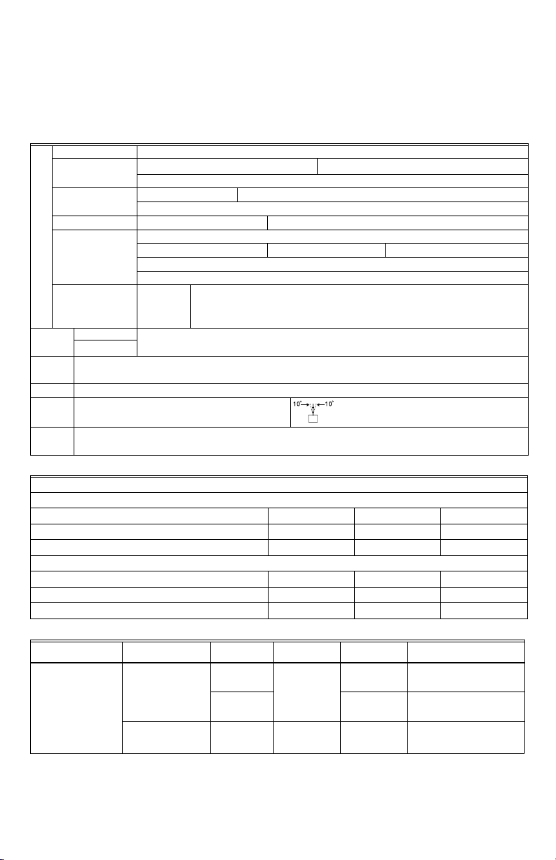
ENVIRONMENT FOR OPERATION, STORAGE AND TRANSPORTATION
DO NOT expose the VFD to an improper environment, such as dust, direct sunlight, corrosive/inflammable gases,
humidity, liquid and vibration environment. The salt in the air must be less than 0.01mg/cm
2
every year.
Installation location IEC60364-1/IEC60664-1 Pollution degree 2, Indoor use only
o
Surrounding
Temperature
Rated Humidity
Storage: -25
Non-condensation, non-frozen
Operation: Max. 90% Storage/Transportation: Max. 95%
C / -13oF ~ +70oC / 167oF Transportation: -25 oC / -13oF ~ +70 oC / 167oF
No condensing water
Air Pressure Operation/ Storage: 86 to 106 kPa Transportation: 70 to 106 kPa
IEC721-3-3
Environment
Pollution Level
Operation: Class 3C2; Class 3S2 Storage: Class 2C2; Class 2S2 Transportation: Class 1C2; Class 1S2
No concentrate
Conformal coated boards
If VFD is installed at altitude 0~1000m, follow normal operation restriction. If it is installed
at altitude 1000~3000m, decrease 2% of rated current or lower 0.5
o
C of temperature for
every 100m increase in altitude. Maximum altitude for Corner Grounded is 2000m.
o
(under normal installation
Package
Drop
Vibration
Impact
Operation
Position
Plenum
Rating
Altitude Operation
Storage
Tra ns por ta tio n
ISTA procedure 1A(according to weight) IEC60068-2-31
1.0mm, peak to peak value range from 2Hz to 13.2 Hz; 0.7G~1.0G range from 13.2Hz to 55Hz; 1.0G range from 55Hz to
512 Hz. Comply with IEC 60068-2-6
IEC/EN 60068-2-27
Max. allowed offset angle ±10
position)
Compliance with UL 508C, the Standard for Power Conversion Equipments, 3rd Edition, and the Canadian Standard for
Industrial Control Equipment, C22.2-No. 14.
Motor Cable Lengths
For Models 7.5HP/5.5kW and above:
Insulation Level of Motor 1000V 1300V 1600V
460VAC Input Voltage 66ft 328ft 1312ft
230VAC Input Voltage 1312ft 1312ft 1312ft
For Models 5HP/3.7kW and below:
Insulation Level of Motor 1000V 1300V 1600V
460VAC Input Voltage 66ft 165ft 165ft
230VAC Input Voltage 328ft 328ft 328ft
Model Frame Top cover Conduit Box
HCRDAxxxxx1000T
HCRDCxxxxx1000T
Frame A~C
230V: 0.75-33kW
1-40hp
460V: 0.75~37kW
1-50hp
Frame D~E
230V:≥37kW/50hp
460V:≥45kW/60hp
Remove top
cover Standard
Standard with
top cover
N/A With conduit
conduit plate
box
Protection
Level
IP20/UL Open
Ty pe
IP20/UL Type1/
NEMA1
IP20/UL Type1/
NEMA1
Temperature*
HD: -10-50
ND: -10-40
HD: -10-40
ND: -10-40
HD: -10-40
ND: -10-40
Operation
o
C (14-120o F)
o
C (14-104o F)
o
C (14-104o F)
o
C (14-104o F)
o
C (14-104o F)
o
C (14-104o F)
* HD = Heavy Duty, higher overload rating. ND = Normal Duty, Standard HVAC applications
NOTE: To prevent personal injury, please make sure that the case and wiring are installed according to this instruc-
tion. The figures in this instruction are only for reference, they may be slightly different from the one you have
but it will not affect your customer rights. The installation instruction may revise without prior notice. Please
refer to our distributors or download the updated version at http://www.customer.honeywell.com/VFD.
3 62-0410—04
Page 4
HONEYWELL CORE DRIVE
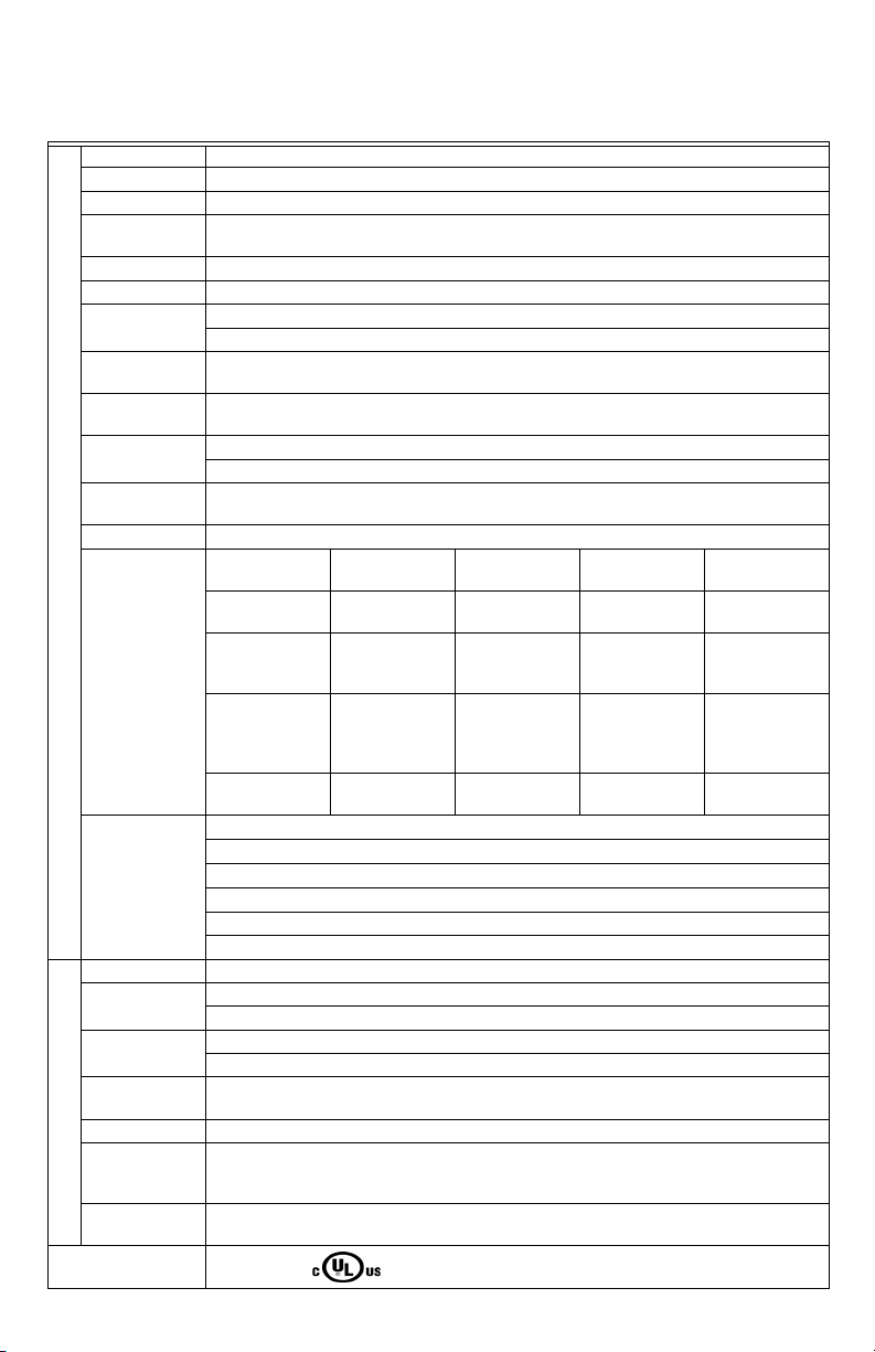
SPECIFICATION TABLES
Table 1. GENERAL SPECIFICATIONS
Control Method 1: V/F (V/F control); 2: SVC (Sensorless Vector Control)
Starting Torque Reach up to 150% or above at 0.5Hz.
V/F Curve 4 point adjustable V/F curve and square curve
Speed Response
Ability 5Hz
Torque Limit Heavy Duty: Max.170% torque current
Torque Accuracy ±5%
Max. Output
Frequency (Hz)
Frequency Output
Accuracy
Output Frequency
Resolution
Overload Tolerance
Frequency Setting
Signal 0~+10V, 4~20mA, 0~20mA, pulse input
Accel./Deccel. Time 0.00~600.00/0.0~6000.0 seconds
Control Characteristics
Main control
function
Fan Control
Motor Protection Electronic thermal relay protection
Over-current
Protection
Over-voltage
Protection
Over-temperature
Protection Built-in temperature sensor
Stall Prevention Stall prevention during acceleration, decceleration and running independently
Restart After
Instantaneous
Protection Characteristics
Power Failure Parameter setting up to 20 seconds
Grounding Leakage
Current Protection Leakage current is higher than 50% of rated current of the AC motor drive
International
Certifications CE, GB 12668.3
62-0410—04 4
230V series: 600.00Hz (55kw and above: 400.00Hz);
460V series: 600.00Hz (90KW and above: 400.00Hz)
Digital command:±0.01%, -10C~+ 40C, Analog command: ±0.1%, 25±10C
Digital command: 0.01Hz, Analog command: max. output frequency x 0.03/60 Hz (±11 bit)
Normal duty: 120% of rated current for 1 minute
Heavy duty: 120% of rated current for 1 minute;160% of rated current for 3 seconds
Fault restart Parameter copy Dwell BACnet COMM Momentary power
Speed search Over-torque
S-curve accel/
deccel
Slip compensation Torque
Smart Stall PID control (with
230V series
Model HCRDA0200B1000T (20HP) and above are PWM controlled
Model HCRDA0150B1000T (15HP) and below are on/off switch controlled
460V series
Model HCRDC0200B1000T and above are PWM controlled
Model HCRDC0150B1000T (15HP) and below are on/off switch controlled
Normal Duty: Over-current protection for 240% rated current
Current clamp Normal duty: 170~175%
230: drive will stop when DC-BUS voltage exceeds 410V
460: drive will stop when DC-BUS voltage exceeds 820V
detection
3-wire sequence Auto-Tuning
compensation
sleep function)
Torque limit 16 preset speed
(rotational,
stationary)
JOG frequency MODBus
Energy saving
control
options
Frequency upper/
lower limit settings
communication
(RS-485 RJ45,
max. 115.2 kbps)
loss ride thru
Accel/Deccel. time
switch
Cooling fan on/off
switch
DC injection braking
at start/stop
Page 5
HONEYWELL CORE DRIVE
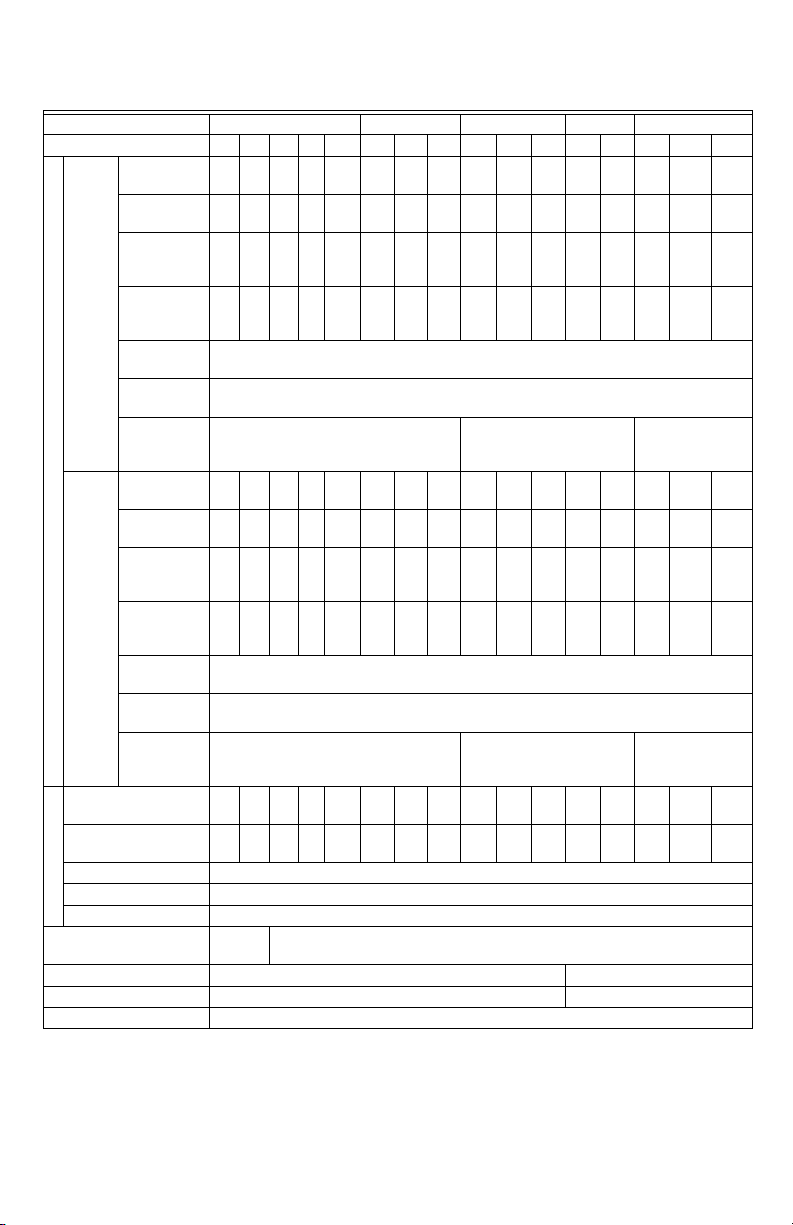
Table 2. 230V Series
Frame size A B C D E
Model HCRDAxxxxx1000T
Rated Output
Capacity (kVA) 2 3 4 6 8.4 12 18 24 30 36 42 58 72 86 110 128
Rated Output
Current (A) 5 7.5 10 15 21 31 46 61 75 90 105 146 180 215 276 322
Applicable
Motor Output
(kW)
Normal
“HVAC”
Applicable
Duty -
Motor Output
Variable
(HP)
Torque
Overload
tolerance 120% of rated current for 1 minute
Max. output
frequency (Hz) 600.00Hz (55KW~: 400.00Hz)
Carrier
Frequency
(kHz)
Rated Output
Output Rating
Capacity (kVA)
Rated Output
Current (A)
Applicable
Motor Output
(kW)
Heavy
Applicable
Duty -
Motor Output
Constant
(HP)
Torque
Overload
tolerance
Max. output
frequency (Hz)
Carrier
Frequency
(kHz)
Input Current (A) Normal
Duty
Input Current (A) Heavy
Duty
Rated Voltage/Frequency 3-phase AC 200V~240V (-15% ~ +10%), 50/60Hz
Input Rating
Operating Voltage Range 170~265Vac
Frequency Tolerance 47~63Hz
Cooling method
Braking Chopper Frame A,B,C: Built-in Frame D and above: Optional
DC choke Frame A, B,C: Optional Frame D and above: 3% built-in
EMI Filter Optional
1hp 2hp 3hp 5hp 7.5hp 10hp 15hp 20hp 25hp 30hp 40hp 50hp 60hp 75hp 100hp 125hp
0.75 1.5 2.2 3.7 5.5 7.5 11 15 18.5 22 30 37 45 55 75 90
1 2 357.510152025 3040506075100125
2~15kHz (8KHz) 2~10kHz (6kHz) 2~9kHz (4KHz)
1.823.24.46.81013202630364858 72 86 102
4.6 5 8 11 17 25 33 49 65 75 90 120 146 180 215 255
0.4 0.75 1.5 2.2 3.7 5.5 7.5 11 15 18.5 22 30 37 45 55 75
0.5 1 2 3 5 7.5 10 15 20 25 30 40 50 60 75 100
120% of rated current for 1 minute, 160% of rated current for 3 seconds
600.00Hz(55KW~: 400.00Hz)
2~15kHz (8KHz) 2~10kHz (6kHz)` 2~9kHz(4KHz)
6.4 9.6 15 22 25 35 50 65 83 100 116 146 180 215 276 322
3.9 6.4 12 16 20 28 36 52 72 83 99 124 143 171 206 245
Natural
Fan Cooling
Cooling
5 62-0410—04
Page 6
HONEYWELL CORE DRIVE
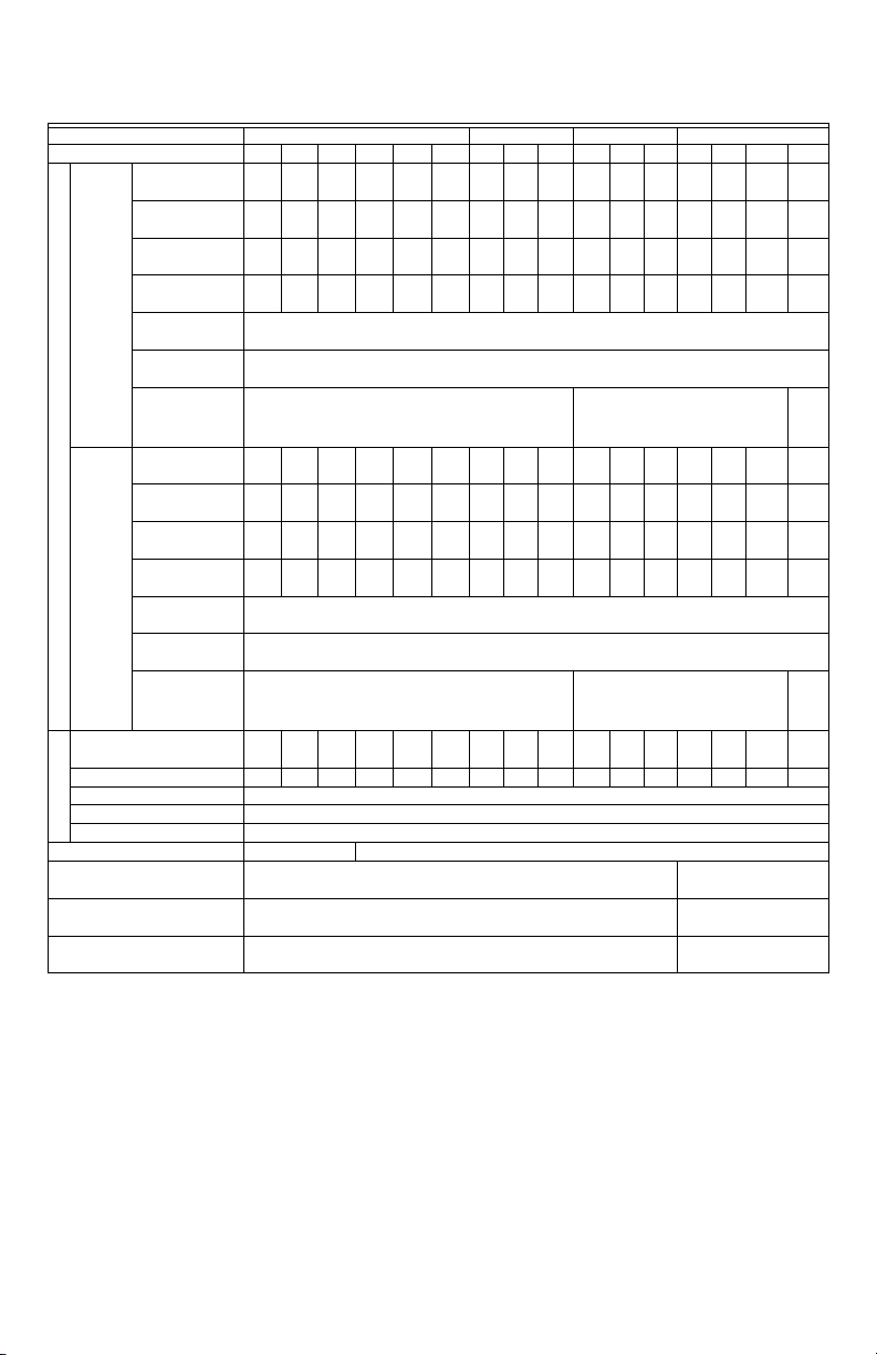
Table 3. 460V Series
Frame A B C D
Models HCRDCxxxxx1000T 1hp 2hp 3hp 5hp 7.5hp 10hp 15hp 20hp 25hp 30hp 40hp 50hp 60hp 75hp 100hp 125hp
Output Rating
Input Rating
Rated Output
Capacity (kVA) 2.4 2.9 4 6 9.6 11.2 18 24 29 36 45 57 73 88 115 143
Rated Output
Current (A) 3 3.7 5 7.5 12 14 22.5 30 36 45 56 72 91 110 144 180
Applicable Motor
Output (kW) 0.75 1.5 2.2 3.7 5.5 7.5 11 15 18.5 22 30 37 45 55 75 90
Normal
Applicable Motor
“HVAC”
Output (HP) 1 2 3 5 7.5 10 15 20 25 30 40 50 60 75 100 125
Duty -
Overload
Variable
Torque
tolerance
Max. output
frequency (Hz)
120% of rated current for 1 minute
600.00Hz (90KW~: 400.00Hz)
Carrier Frequency
2~15kHz (8KHz) 2~10kHz (6kHz)
120% of rated current for 1 minute;160% of rated current for 3 seconds
600.00Hz(90KW~: 400.00Hz)
Heavy
Duty -
Constant
Torque
(kHz)
Rated Output
Capacity (kVA)
Rated Output
Current (A)
Applicable Motor
Output (kW)
Applicable Motor
Output (HP)
Overload
tolerance
Max. output
frequency (Hz)
2.2 2.4 3.2 4.8 8.4 10 14 19 25 30 36 48 58 73 88 120
2.8 3 4 6 10.5 12 18 24 32 38 45 60 73 91 110 150
0.4 0.75 1.5 2.2 4 5.5 7.5 11 15 18.5 22 30 37 45 55 75
0.5 1 2 3 5 7.5 10 15 20 25 30 40 50 60 75 100
Carrier Frequency
(kHz)
Input Current (A) Normal
Duty
Input Current (A) Heavy Duty
4.3 5.4 7.4 11 18 20 25 33 39 47 58 76 91 110 144 180
3.5 4.3 5.9 8.7 15.5 17 20 26 35 40 47 63 74 101 114 157
2~15kHz (8KHz) 2~10kHz (6kHz)
Rated Voltage/Frequency 3-phase AC 380V~480V (-15%~+10%), 50/60Hz
Operating Voltage Range 323~528Vac
Frequency Tolerance 47~63Hz
Cooling method Natural Cooling Fan Cooling
Braking Chopper
DC choke
EMI Filter
Frame A,B,C: Built-in
Frame A, B,C: Optional
Frame A, B, C - EMI filter NOT built-in
2~9
kHz
(4KHz
2~9
kHz
(4KHz
Frame D and above:
Optional
Frame D and above: 3%
DC built-in
Frame D and above:
Optional
62-0410—04 6
Page 7
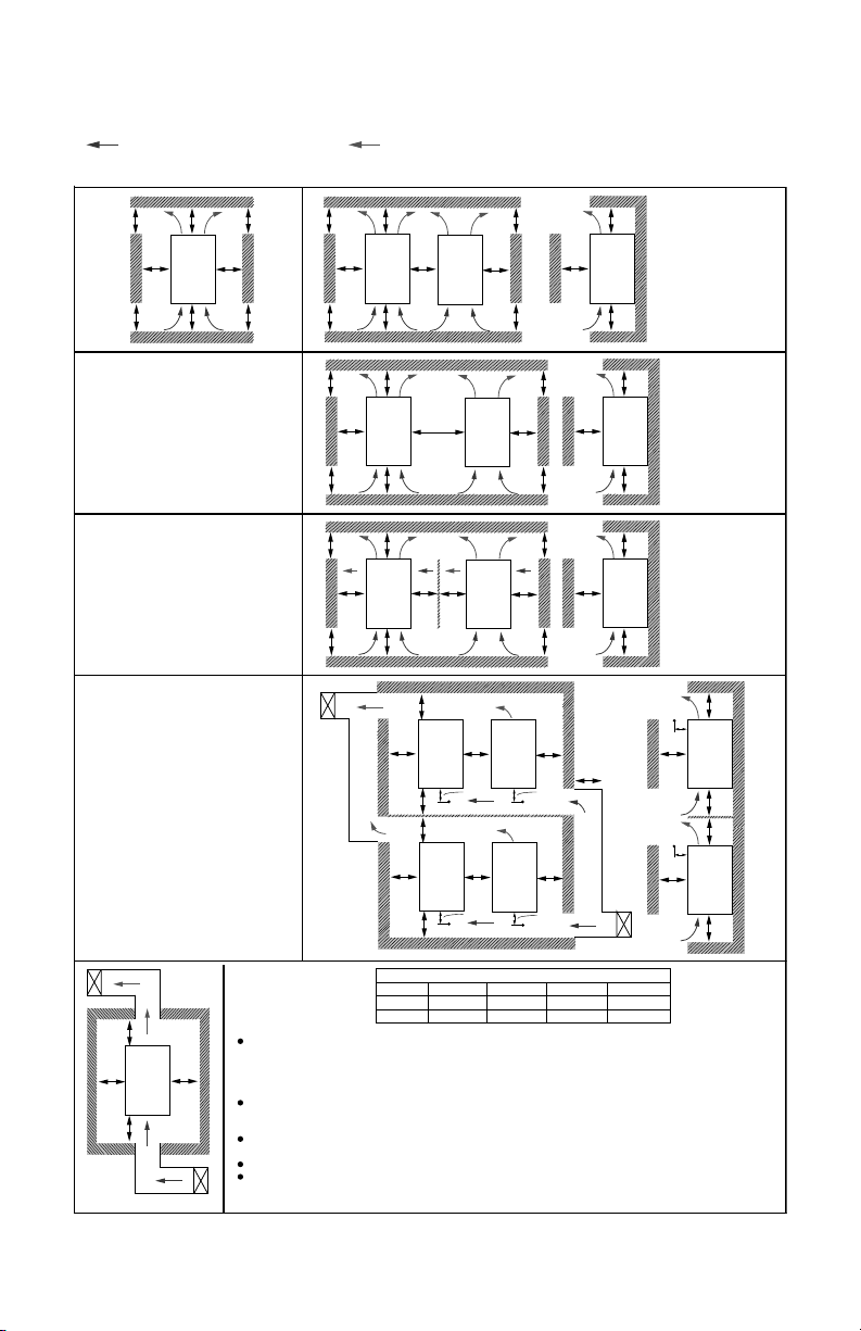
MINIMUM MOUNTING CLEARANCES
AA
A
A
A
A
B
B
A
A
B
A
A
C
A
A
B
A
A
D
A
A
B
A
A
2B
A
A
B
A
A
D
A
A
B
A
A
A
A
D
B
B
A
A
B
A
D
Ta*
B
A
A
C
B
B
A
A
C
B
50 mm
Ta
50 mm
Ta
50 mm
Ta
50 mm
Ta
A
A
D
Ta*
A
FRAME A, B, C
MULTIPLE DRIVES: INDEPENDENT
INSTALLATION IN HORIZONTAL
FRAME D, E
MULTIPLE DRIVES: INDEPENDENT
INSTALLATION IN HORIZONTAL
INSTALL A BARRIER BETWEEN THE
DRIVES
FRAME A, B, C
MULTIPLE DRIVES: INDEPENDENT
INSTALLATION
TA: FRAME A~E
IT IS SUGGESTED TO INSTALL A
BARRIER BETWEEN THE DRIVES.
ADJUST THE SIZE OF THE BARRIER TILL
THE TEMPERATURE OF THE FAN ON THE
INFLOW SIDE IS LOWER THAN THE
OPERATION TEMPERATURE.
(REFER TO THE RIGHT FIGURE)
OPERATION TEMPERATURE IS THE
TEMPERATURE MEASURED 50MM AWAY
FROM THE INFLOW SIDE OF THE FAN.
MINIMUM MOUNTING CLEARANCE
FRAME
A~C
A (mm/in) B (mm/in) C (mm/in)
D (mm/in)
D~F
60/1.2
100/3.3
30/0.6
50/1.7
10/0.2
0
0
-
A
B
B
A
INVERTER
INVERTER
INVERTER
INVERTER
INVERTER
INVERTER
INVERTER
INVERTER
INVERTERINVERTER
INVERTER
INVERTER
INVERTER
INVERTER
INVERTER
INVERTER
INVERTER
NOTE:
THE MOUNTING CLEARANCES SHOWN IN THE LEFT FIGURE ARE NOT FOR INSTALLING THE DRIVE IN A
CONFINED SPACE (SUCH AS CABINET OR ELECTRIC BOX). WHEN INSTALLING IN A CONFINED SPACE,
BESIDES THESE SAME MINIMUM MOUNTING CLEARANCES, IT NEEDS TO HAVE THE VENTILATION
EQUIPMENT OR AIR ONDITIONER TO KEEP THE SURROUNDING TEMPERATURE LOWER THAN THE
OPERATION TEMPERATURE.
THE FOLLOWING TABLE SHOWS HEAT DISSIPATION AND THE REQUIRED AIR VOLUME WHEN INSTALLING
A SINGLE DRIVE IN A CONFINED SPACE. WHEN INSTALLING MULTIPLE DRIVES, THE REQUIRED AIR
VOLUME SHALL BE MULTIPLIED BY THE NUMBER OF DRIVES.
REFER TO THE CHART (AIR FLOW RATE FOR COOLING) FOR VENTILATION EQUIPMENT DESIGN AND
SELECTION.
REFER TO THE CHART (POWER DISSIPATION) FOR AIR CONDITIONER DESIGN AND SELECTION.
IT IS THE MINIMUM DISTANCE REQUIRED FOR FRAME A~D. IF DRIVES ARE INSTALLED CLOSER THAN
THE MINIMUM MOUNTING CLEARANCE, THE FAN MAY NOT FUNCTION PROPERLY.
(BLUE ARROW) INFLOW
(FRAME A-E)
SINGLE DRIVE: INDEPENDENT INSTALLATION
(RED ARROW) OUTFLOW
(FRAME A-C)
PARALLEL MOUNTING IN HORIZONTAL
M31500
(Appearances shown in the following figures are only for reference)
HONEYWELL CORE DRIVE
7 62-0410—04
Fig. 1. Minimum Mounting Clearances.
Page 8

HONEYWELL CORE DRIVE
Table 4. Air Flow Requirements
Air flow rate for cooling Power Dissipation
Flow Rate (cfm) Flow Rate (m3/hr)
Power Dissipation (Watts)
Loss
External
Model 230Vac
Frame
External Internal Total External Internal Total
Size
(Heat
sink)
Internal Total
HCRDA0010A1000T A - - - - - - 40 31 71
HCRDA0020A1000T A - - - - - - 61 39 100
HCRDA0030A1000T A 14 - 14 24 - 24 81 45 126
HCRDA0050A1000T A 14 - 14 24 - 24 127 57 184
HCRDA0075A1000T A 10 - 10 17 - 17 158 93 251
HCRDA0100B1000T B 40 14 54 68 24 92 291 101 392
HCRDA0150B1000T B 66 14 80 112 24 136 403 162 565
HCRDA0200B1000T B 58 14 73 99 24 124 570 157 727
HCRDA0250C1000T C 166 12 178 282 20 302 622 218 840
HCRDA0300C1000T C 166 12 178 282 20 302 777 197 974
HCRDA0400C1000T C 146 12 158 248 20 268 878 222 1100
HCRDA0500D1000T D 179 30 209 304 51 355 1271 311 1582
HCRDA0600D1000T D 179 30 209 304 51 355 1550 355 1885
HCRDA0750E1000T E 228 73 301 387 124 511 1762 489 2251
HCRDA1000E1000T E 228 73 301 387 124 511 2020 574 2594
HCRDA1250E1000T E 246 73 319 418 124 542 2242 584 3026
Model 460Vac
HCRDC0010A1000T A - - - - - - 35 32 67
HCRDC0020A1000T A - - - - - - 44 31 75
HCRDC0030A1000T A - - - - - - 58 43 101
HCRDC0050A1000T A 14 - 14 24 - 24 92 60 152
HCRDC0075A1000T A 10 - 10 17 - 17 135 99 234
HCRDC0100A1000T A 10 - 10 17 - 17 165 164 439
HCRDC0150B1000T B 40 14 54 68 24 92 275 93 380
HCRDC0200B1000T B 66 14 80 112 24 136 370 194 564
HCRDC0250B1000T B 58 14 73 99 24 124 370 194 564
HCRDC0300C1000T C 99 21 120 168 36 204 455 358 813
HCRDC0400C1000T C 99 21 120 168 36 204 609 363 972
HCRDC0500C1000T C 126 21 147 214 36 250 845 405 1250
HCRDC0600D1000T D 179 30 209 304 51 355 1056 459 1515
HCRDC0750D1000T D 179 30 209 304 51 355 1163 669 1832
HCRDC1000D1000T D 179 30 209 304 51 355 1639 657 2296
HCRDC1250D1000T D 186 30 216 316 51 367 1787 955 2742
The required airflow shown in chart is for installing single drive in a confined space.
When installing the multiple drives, the required air volume should be the required air volume for single drive multiplied
by the number of the drives.
Heat dissipation for each model is calculated by rated voltage, current and default carrier at full load, full speed, and
maximum ambient temperature
62-0410—04 8
Page 9

SPECIFICATIONS FOR WIRING TERMINALS
M31491
FIGURE 1
26.5 MAX.
8.2 MIN.
31 MAX.
70 MAX.
16
+0
-4
17 MAX.
65 MAX.
8.2 MIN.
28 MAX.
FIGURE 2
WIRE
HEAT
SHRINK
TUBE
RING LUG
FIGURE 3
13 MIN.
Table 5. Specifications for Wiring Terminals (refer to wiring diagram)
Control terminals
Main terminals
Max. Wire
Models VFD-
HCRDA0010A1000T
HCRDA0020A1000T
HCRDA0030A1000T 12 AWG (3.3mm2)
HCRDA0050A1000T 10 AWG (5.3mm2)
HCRDA0075A1000T 10 AWG (5.3mm
HCRDC0010A1000T 14 AWG (2.1mm
HCRDC0020A1000T 14 AWG (2.1mm
(8.4mm2)
HCRDC0030A1000T 14 AWG (2.1mm
HCRDC0050A1000T 14 AWG (2.1mm2)
HCRDC0075A1000T 10 AWG (5.3mm2)
HCRDC0100A1000T 10 AWG (5.3mm
HCRDA0100B1000T
HCRDA0150B1000T 4 AWG (21.2mm2)
HCRDA0200B1000T 4 AWG (21.2mm2)
HCRDC0150B1000T 8 AWG (8.4mm2)
HCRDC0200B1000T 8 AWG (8.4mm2)
(21.2mm
HCRDC0250B1000T 6 AWG (13.3mm2)
HCRDA0250C1000T
HCRDA0300C1000T 1/0 AWG (53.5mm2)
HCRDA0400C1000T 1/0 AWG (53.5mm2)
HCRDC0300C1000T 4 AWG (21.2mm2)
HCRDC0400C1000T 4 AWG (21.2mm2)
1/0 AWG
(53.5mm2)
HCRDC0500C1000T 2 AWG (33.6mm2)
HCRDA0500D1000T
HCRDA0600D1000T 4/0 AWG (107mm2)
HCRDC0600D1000T 1/0 AWG (53.5mm2)
HCRDC0750D1000T 2/0 AWG (67.4mm2)
HCRDC1000D1000T 4/0 AWG (107mm2)
4/0 AWG
(107mm2)
HCRDC1250D1000T 4/0 AWG (107mm2)
HCRDA0750E1000T
HCRDA1000E1000T
4/0 AWG*2
(107mm2*2)
HCRDA1250E1000T
Wire Gauge: 26-16AWG. (0.1281-1.318mm2)
Torque (±10%): 5kg-cm[4.31 lb-in.] (0.49Nm), 5kg-cm[4.31 lb-in.] (0.49Nm)
Gauge Min. Wire Gauge Torque (±10%) Note
14 AWG (2.1mm2)
14 AWG (2.1mm2)
2
)
2
8 AWG
4 AWG
8 AWG (8.4mm2)
2
)
)
2
)
2
)
2
)
M4 20kg-cm
(17.4 lb-in.)
(1.962Nm)
M5 35kg-cm
(30.4 lb-in.)
(3.4335Nm)
Terminal D+[+2 & +1]:
Torque 45 Kg-cm [39.0 lb-in.] (4.415Nm) (±10%)
Use 600V, 90oC wired for UL installation for
HCRDA0200B1000T install in ambient temperature
exceeds 40oC.
1 AWG (42.4mm2)
M8 80kg-cm
(69.4 lb-in.)
(7.848Nm)
Terminal D+[+2 & +1]:
Torque 90 Kg-cm [78.2 lb-in.] (8.83Nm) (±10%)
Use 600V, 90oC wired for UL installation for
HCRDA0400C1000T install in ambient temperature
exceeds 40oC.
4/0 AWG (107mm2)
Use the specified insulated heat shrink tubing that
complies with UL (600C, YDPU2). Must use 90oC wire
for HCRDA0600D1000T & HCRCD1250D1000T.
28 MAX.
8.2 MIN.
RING
LUG
28 MAX.
(Figure 1) The usage of ring terminals should comply
with the specifications shows in the figure.
(Figure 2) Grounding wire specification: 300MCM*2
[152 mm2*2]
Torque M8 180Kg-cm [156 lb-in.] (17.64Nm) (±10%)
(Figure 3) The figure shows the specification of
insulated heat shrink tubing that complies with UL
(600C, YDPU2)
1/0 AWG*2
2
(53.5mm
2/0 AWG*2
(67.4mm2*2)
3/0AWG*2
(85mm2*2)
M8 200kg-cm
(173 lb-in.)
(19.62Nm)
*2)
M8 200kg-cm
(173 lb-in.)
HONEYWELL CORE DRIVE
RING LUG
17 MAX.
HEAT
13 MIN.
SHRINK
48 MAX.
WIRE
TUBE
M31492
9 62-0410—04
Page 10

HONEYWELL CORE DRIVE
Table 6. Fuse and Non-fuse Circuit Breaker
Input Current I(A) Line Fuse Recommended non-
Model 230V
Normal Duty Heavy Duty
I (A) Bussmann P/N
fuse breaker (A) **
HCRDA0010A1000T 6.4 3.9 15 JJN-15 15
HCRDA0020A1000T 9.6 6.4 20 JJN-20 20
HCRDA0030A1000T 15 12 30 JJN-30 30
HCRDA0050A1000T 22 16 40 JJN-40 40
HCRDA0075A1000T 25 20 50 JJN-50 50
HCRDA0100B1000T 35 28 60 JJN-60 60
HCRDA0150B1000T 50 36 100 JJN-100 100
HCRDA0200B1000T 65 52 125 JJN-125 125
HCRDA0250C1000T 83 72 150 JJN-150 150
HCRDA0300C1000T 100 83 200 JJN-200 200
HCRDA0400C1000T 116 99 225 JJN-225 225
HCRDA0500D1000T 146 124 250 JJN-250 250
HCRDA0600D1000T 180 143 300 JJN-300 300
HCRDA0750E1000T 215 171 400 JJN-400 400
HCRDA1000E1000T 276 206 450 JJN-450 450
HCRDA1250E1000T 322 245 600 JJN-600 600
Input current (A) Line Fuse Recommended non-
Model 460V
Normal Duty Heavy Duty
I (A) Bussmann P/N
fuse breaker (A) **
HCRDC0010A1000T 4.3 3.5 10 JJS-10 5
HCRDC0020A1000T 5.4 4.3 10 JJS-10 10
HCRDC0030A1000T 7.4 5.9 15 JJS-15 15
HCRDC0050A1000T 11 8.7 20 JJS-20 20
HCRDC0075A1000T 18 15.5 30 JJS-30 30
HCRDC0100A1000T 20 17 40 JJS-40 40
HCRDC0150B1000T 25 20 50 JJS-50 50
HCRDC0200B1000T 33 26 60 JJS-60 60
HCRDC0250B1000T 39 35 75 JJS-75 75
HCRDC0300C1000T 47 40 100 JJS-100 100
HCRDC0400C1000T 58 47 125 JJS-125 125
HCRDC0500C1000T 76 63 150 JJS-150 150
HCRDC0600D1000T 91 74 175 JJS-175 175
HCRDC0750D1000T 110 101 250 JJS-250 250
HCRDC1000D1000T 144 114 300 JJS-300 300
HCRDC1250D1000T 180 157 300 JJS-300 300
** To comply with UL standard: Per UL 508, paragraph 45.8.4, part a:
The rated current of the breaker shall be 2~4 times of the maximum rated input current of AC motor drive.
NOTE: Fuses with specification smaller than the data in the following table are allowed
62-0410—04 10
Page 11

Table 7. Dimensions for Frames A, B, C in mm [inch].
208/230Vac 460Vac HP Weight
HCRDA0010A1000T HCRDC0010A1000T 1 2.8 A 130
HCRDA0020A1000T HCRDC0020A1000T 2 2.8
HCRDA0030A1000T HCRDC0030A1000T 3 2.8
HCRDA0050A1000T HCRDC0050A1000T 5 2.8
HCRDA0075A1000T HCRDC0075A1000T 7.5 2.8
HCRDC0100A1000T 10 2.8
HCRDA0100B1000T 10 4.6 B 190
HCRDA0150B1000T HCRDC0150B1000T 15 4.6
HCRDA0200B1000T HCRDC0200B1000T 20 5.6
HCRDC0250B1000T 25
HCRDA0250C1000T 25 10.5 C 250
HCRDA0300C1000T HCRDC0300C1000T 30 10.5/8.7
HCRDA0400C1000T HCRDC0400C1000T 40 10.5/8.7
HCRDC0500C1000T 50 9.4
Frame W H D W1 H1 D1* S1
(kg.)
[5.12]
[7.48]
[9.84]
D1*: Flange mounting Unit: mm [inch]
FRAME A
W
W1
CORE
250
[9.84]
[6.69]
320
[12.60]
[7.48]
400
[15.75]
[8.27]
SEE DETAIL A
170
190
210
116
[4.57]
173
[6.81]
231
[9.09]
HONEYWELL CORE DRIVE
236
45.8
D
[1.80]
77.9
[3.07]
92.9
[3.66]
6.2
[.24]
8.5
[0.33]
8.5
[0.33]
[9.29]
303
[11.93]
381
[15.00]
φ1 φ2 φ3
22.2
[.87]
22.2
[0.87]
22.2
[0.87]
D1
34
[1.34]
34
[1.34]
34
[1.34]
28
[1.1]
28
[1.10]
50
[1.97]
SEE DETAIL B
H
H1
CORE
1
1
3
2
SEE DETAIL B
3
DETAIL A (MOUNTING HOLE)
DETAIL B (MOUNTING HOLE)
Fig. 2. Frame A: Units in mm (inches). See also Table 7.
11 62-0410—04
S1
S1
M31495
Page 12

HONEYWELL CORE DRIVE
M31497
SEE DETAIL A
SEE DETAIL B
DETAIL A (MOUNTING HOLE)
DETAIL B (MOUNTING HOLE)
S1
S1
W1
W
D1
D
H1
H
1
3
2
1
1
1
3
CORE
CORE
FRAME B
W
W1
CORE
CORE
SEE DETAIL A
H
H1
D
D1
FRAME C
SEE DETAIL B
1
3
1
2
1
3
Fig. 3. Frame B: Units in mm (inches). See also Table 7.
S1
DETAIL A (MOUNTING HOLE)
S1
DETAIL B (MOUNTING HOLE)
M31496
62-0410—04 12
Fig. 4. Frame C: Units in mm (inches). See also Table 7.
Page 13

Tab le 8 . Dimensions for Frames D and E.
SEE DETAIL A
SEE DETAIL B
W1
W
D1
D
H1
H
DETAIL B
(MOUNTING HOLE)
DETAIL A
(MOUNTING HOLE)
S1
S1
1
1
3
3
2
2
M31498
CORE
CORE
208/230Vac 460Vac HP Weight
HCRDA0500D1000T 50 35.5 D 330
HCRDA0600D1000T HCRDC0600D1000T 60 35.5
HCRDC0750D1000T 75 35.5
HCRDC1000D1000T 100 40.5
HCRDC1250D1000T 125 40.5
HCRDA0750E1000T
75 45.7
HCRDA1000E1000T 100 46.2
HCRDA1250E1000T 125 54.7
Frame W H D W1 H1 D1* S1
(Kg.)
[12.99]
E 370
[14.57]
*D1 Flange mounting
FRAME D
688.3
[27.10]
715.8
[28.18]
275
[10.83]
300
[11.81]
285
[11.22]
335
[13.19
550
[21.65]
589
[23.19]
HONEYWELL CORE DRIVE
φ1 φ2 φ3
107.2
11.0
76.2
[4.22]
143.0
[5.63]
[0.43]
13.0
[0.51]
[3.00]
22.0
[0.87]
34.0
[1.34]
34.0
[1.34]
22.0
[0.87]
92.0
[3.62]
Fig. 5. Frame D: Units in mm (inches). See also Table 8.
13 62-0410—04
Page 14

HONEYWELL CORE DRIVE
SEE DETAIL A
SEE DETAIL B
DETAIL B
(MOUNTING HOLE)
DETAIL A
(MOUNTING HOLE)
S3
D2
S1
S2
D1
D
W1
W
H1
H2
H3
H
M31499
1
1
2
2
2
2
3
3
CORE
CORE
FRAME E
Fig. 6. Frame E: Units in mm (inches). See also Table 8.
62-0410—04 14
Page 15

KEYPAD BASICS
M31501
CORE
F1
F2
F3
F4
ESC
MENU
AUTO
HAND
STOP
RESET
FWD
REV
FWD
ENTER
ERR
COMM
RUN
RUN
REV
FWD
ENTER
ESC
MENU
Table 9. Descriptions of Keypad Functions
Key Descriptions
This is the RUN/START command to the VFD when in Hand/Keypad control only.
HONEYWELL CORE DRIVE
RUN
STOP
RESET
It can operate the AC motor drive by the function setting and the RUN LED will be ON.
Stop Command Key. This key has the highest processing priority in any situation. Drive will
always STOP when this button is pressed.
The RESET key can be used to reset the drive after the fault occurs. For those faults that can’t
be reset by the RESET key, see the fault records after pressing MENU key for details.
This key controls the operational direction of the motor. NOT activated out of the box.
Press ENTER and go to the next submenu. If at the parameter level, press enter to modify and
press enter to save changes
ESC key function is to leave current menu and return to the last menu. It is also functioned as a
return key in the sub-menu.
Press menu to return to main menu. See main menu descriptions on following pages.
15 62-0410—04
Page 16

HONEYWELL CORE DRIVE
HAND
AUTO
RUN
STOP
RESET
REV
FWD
HAND
AUTO
RIGHT and LEFT arrows to move the cursor with a numeric parameter, or to enter into and out
of menus.
UP and DOWN arrows used to change numeric parameter values, or cycle through menu
options.
Table 9. Descriptions of Keypad Functions
F1
F3
LED Descriptions
Function Keys - will have different functions at different times as displayed on the screen. Used
F2
during Wizard Mode.
F4
Pressing the HAND key will take the VFD into Hand control, where the user can control the
motor Frequency and START and STOP.
Pressing this key will revert the VFD to remote/Automatic control from a remote speed and start
command source.
Table 10. Descriptions of LED Functions
Steady ON: operation indicator for the VFD, including DC brake, zero speed, standby, restart
after fault and speed search.
Blinking: VFD is decelerating to stop.
Steady OFF: VFD is not running.
Steady ON: VFD is stopped.
Blinking: VFD is in the standby status.
Steady OFF: VFD running.
Operation Direction LED (green: forward running, red: reverse running).
Blinking: drive is changing the operation direction.
HAND LED: When HAND LED is on (HAND mode); when HAND LED is off (AUTO mode).
AUTO LED: When AUTO LED is on (AUTO mode); when AUTO LED is off (HAND mode).
62-0410—04 16
Page 17

START-UP WIZARD GUIDE
Table 11. Honeywell Commissioning Start-Up Wizard
Screen #Screen
Verbiage
1 Boot
Screen
2 Selection
Screen
3 Select
Language
4 Clock Time
and DATE
5 Motor
Voltage
6 Motor
Current
7 Motor
FREQ
8 Motor RPM Motor's rated RPM based upon Motor Name
9 ACCEL
TIME
10 DECEL
TIME
11, 12, 13PRESET
SPEED
1,2,3
14 Analog
Input
15 MIN
Frequency
16 MAX
Frequency
17 PRESS F4
to SAVE
ALL
Honeywell displayed for 3 seconds N/A
Choose how to interact with the VFD:
Recommendation: Press function key F4 to
start the wizard
Choose the keypad programming language
Use UP and DOWN arrows to change from
default. Press ENTER to accept change.
F1 BACK up one menu (SAME function
throughout WIZARD)
F4 Next Parameter (SAME function
throughout WIZARD)
Select the time (Military) HH:MM:SS and date
YY/MM/DD
Motor's rated voltage based upon Motor
Name Plate data
Motor's rated current in FLA, Full Load AMPs
based upon Motor Name Plate data. Do not
use motor service factor amperage for this
value.
Motor's rated frequency based upon Motor
Name Plate data
Plate data
The time required to accelerate from the
motor’s current speed reference to a new
speed reference
The time required to decelerate from the
motor’s current speed reference to a new
speed reference
Present Speed options. On digital input
closure the VFD will ignore the speed
reference from the analog input and will run at
the programmed speed.
Select the speed reference signal type. 0. 0-10V - Use AVI (Analog Voltage Input terminal)
The minimum frequency at which the motor
will operate
The maximum frequency at which the motor
will operate
Saves all parameter updates - VFD is ready
to operate
Screen Description Screen options
HONEYWELL CORE DRIVE
F4: Initials the START UP WIZARD
Menu: redirects to MAIN MENU
ESC: redirects to MONITOR Screen
1. English
2. Spanish
3. Chinese
4. Portuguese
5. French
Use arrow keys to adjust. Press ENTER to save
changes, F4 to advance without changes.
Press F4 to accept factory defaults. Use arrow keys to
adjust ONLY if needed. PRESS ENTER to save
changes.
Press F4 to accept factory defaults. Use arrow keys to
adjust ONLY if needed. PRESS ENTER to save
changes.
Press F4 to accept factory defaults. Use arrow keys to
adjust ONLY if needed. PRESS ENTER to save
changes.
Press F4 to accept factory defaults. Use arrow keys to
adjust ONLY if needed. PRESS ENTER to save
changes.
Press F4 to accept factory defaults. Use arrow keys to
adjust ONLY if needed. PRESS ENTER to save
changes.
Acceleration time is factory set for typical Fan and
Pump needs. Use arrow keys to adjust. Press ENTER
to save changes, F4 to advance without changes.
Decceleration time is factory set for typical Fan and
Pump needs. Use arrow keys to adjust. Press ENTER
to save changes, F4 to advance without changes.
With the use of MFI (Multifunction inputs) 1, 2, or 3 the
drive can be sent to the programmed speed on digital
input closure (Usage not required in the field). Adjust as
needed or press F4 to accept factory defaults.
1. 4-20mA - Use ACI (Analog current input terminals)
2. 2-10V - Use AVI
3. 0-20mA - Use ACI
Press F4 to accept factory defaults. Use arrow keys to
adjust ONLY if needed. PRESS ENTER to save
changes.
Press F4 to accept factory defaults. Use arrow keys to
adjust ONLY if needed. PRESS ENTER to save
changes.
F1 will escape the user back to the Selection Screen
agai
n
F4 will save parameters and take the user to the display
screen
17 62-0410—04
Page 18

HONEYWELL CORE DRIVE
Copy/Save
1.
2.
3.
Copy/Save
1.2009/05/04
2.
3.
File 1
1.Keypad->VFD
2.VFD->Keypad
3.
Quick Setup
1: V/F Mode
2: SVC Mode
3: My Mode
Keypad Lock
Press ENTER to
Lock Key
Keypad Lock
Press ESC 3sec
to UnLock Key
Displ Setup
1:Contrast
2:Back-Light
3:Text Color
MENU STRUCTURE
NOTE: This menu is accessed when the MENU button is pressed.
Start Wizard Restart the Start-up Wizard: See Wizard instructions
Copy/Save 1. Copy Parameters (4 parameter copies can be stored per keypad)
2. Press Enter on row 1-4, then select save to save parameters or load to upload
parameters to the connect VFD from the saved parameter list.
Fault Record 1. Records the last 6 fault records
2. The first fault is the current or most recent fault
3. Select the fault code for time, date, frequency output, current, voltage, and DC Bus
Voltage at time of fault
4. Press ENTER to view a particular fault and scroll UP and DOWN to see data
Time Setup
Quick Setup Quick Settings Menu contains a list of optional parameter lists for different applications.
MY MODE, where frequency used parameters can be saved is located here.
STARTUP WIZARD parameters are also listed in this menu.
Table 12. Main Menu Structure.
Keypad Lock The keypad is locked when ENTER is pressed. When any key is pressed the following
Language Use the arrow key to move up and down to change the language selection
Display Setup Display Setup Menu allows the user to adjust the backlight time and contract. UP and
Advanced Parameters Full Parameter list setup. Refer to the Full User Manual on the accompanying CD or at
Splash Screen See Full User Manual for details
Main Page See Full User Manual for details
PLC Enabled See Full User Manual for details
Copy PLC See Full User Manual for details
PC Link See Full User Manual for details or customer.honeywell.com
62-0410—04 18
screen will appear.
DOWN arrows are used to adjust settings. ENTER must be pressed for changes to be
saved.
customer.honeywell.com for access
Page 19

HONEYWELL CORE DRIVE
1
2
3
1
2
3
Display error signal
Abbreviated error code
Display error description
WARNING CODES
Table 13. Warning Codes
Warning
Code Keypad Display
CE01 Comm. Error 1 Modbus function code error
CE02 Comm. Error 2 Address of Modbus data is error
CE03 Comm. Error 3 Modbus data error
CE04 Comm. Error 4 Modbus communication error
CE10 Comm. Error 10 Modbus transmission time-out
CP10 Keypad Time Out Keypad transmission time-out
SE1 Save Error 1 Keypad COPY error 1
SE2 Save Error 2 Keypad COPY error 2
SE3 Save Error 3 Keypad COPY error 3
oH1 Over heat 1 warn IGBT over-heating warning
oH2 Over heat 2 warn Capacity over-heating warning
PID PID FBK Error PID feedback error
ANL Analog loss ACI signal error
uC Under Current Low current
AUE Auto-Tune Error Auto tuning error
oSPD Over Speed Warn Over-speed warning
DAvE Deviation Warn Over speed deviation warning
PHL Phase Loss Warn Phase loss
ot1 Over Torque 1 Over torque 1
ot2 Over Torque 2 Over torque 2
oH3 Motor Over Heat Motor over-heating
oSL Over Slip Warn Over slip
tUn Auto Tuning Auto tuning processing
OPHL Output PHL Warn Output phase loss warning
Ecid ExCom ID failed Duplicate MAC ID error
ECLv ExCom pwr loss Low voltage of communication card
Ectt ExCom Test Mode Communication card in test mode
ECFF ExCom Facty def Factory default setting error
ECiF ExCom Inner err Serious internal error
Ecio ExCom IONet brk IO connection break off
ECEF ExCom Link fail Ethernet Link fail
Ecto ExCom Inr T-out Communication time-out for communication card and drive
ECCS ExCom Inr CRC Check sum error for Communication card and drive
ECrF ExCom Rtn def Communication card returns to default setting
ECo0 ExCom MTCP over Modbus TCP exceed maximum communication value
ECo1 ExCom EIP over EtherNet/IP exceed maximum communication value
ECiP ExCom IP fail IP fail
EC3F ExCom Mail fail Mail fail
Ecby ExCom Busy Communication card busy
19 62-0410—04
Description
Page 20

HONEYWELL CORE DRIVE
FAULT CODES AND DESCRIPTIONS
Display error signal
1
2
3
1
Abbreviated error code
2
3
Display error description
NOTE: Additional details and screen shots of the error messages can be found in the full manual.
Fault
Keypad
Code
Fault Desc
ocA oc at accel Over-current during acceleration 1. Short-circuit at motor output: Check for possible poor
(Output current exceeds triple rated current
during acceleration) 2. Acceleration Time too short: Increase the Acceleration Time.
ocd oc at decel Over-current during decceleration 1. Short-circuit at motor output: Check for possible poor
(Output current exceeds triple rated current
during decceleration.)
ocn oc at normal
SPD
ocS oc at stop Hardware failure in current detection Return to the factory
GFF Ground fault Ground fault When (one of) the output terminal(s) is grounded, short circuit
occ Short Circuit Short-circuit is detected between upper
ovA ov at accel DC BUS over-voltage during acceleration
ovd ov at decel DC BUS over-voltage during decceleration
Over-current during steady state operation 1. Short-circuit at motor output: Check for possible poor
(Output current exceeds triple rated current
during constant speed.)
bridge and lower bridge of the IGBT module Return to the factory
(230V: DC 450V; 460V: DC 900V)
(230V: DC 450V; 460V: DC 900V)
Table 14. Fault Codes and Descriptions
Fault Descriptions
Corrective Actions
insulation at the output.
3. AC motor drive output power is too small: Replace the AC
motor drive with the next higher power model.
insulation at the output.
2. Decceleration Time too short: Increase the Decceleration
Time.
3. AC motor drive output power is too small: Replace the AC
motor drive with the next higher power model.
insulation at the output.
2. Sudden increase in motor loading: Check for possible motor
stall.
3. AC motor drive output power is too small: Replace the AC
motor drive with the next higher power model.
current is more than 50% of AC motor drive rated current, the
AC motor drive power module may be damaged.
NOTE: The short circuit protection is provided for AC motor
drive protection, not for protecting the user.
1. Check the wiring connections between the AC motor drive
and motor for possible short circuits, also to ground.
2. Check whether the IGBT power module is damaged.
3. Check for possible poor insulation at the output.
1. Check if the input voltage falls within the rated AC motor
drive input voltage range.
2. Check for possible voltage transients.
3. If DC BUS over-voltage due to regenerative voltage, please
increase the Decceleration Time or add an optional brake
resistor.
1. Check if the input voltage falls within the rated AC motor
drive input voltage range.
2. Check for possible voltage transients.
3. If DC BUS over-voltage due to regenerative voltage, please
increase the Decceleration Time or add an optional brake
resistor.
62-0410—04 20
Page 21

HONEYWELL CORE DRIVE
NOTE: Additional details and screen shots of the error messages can be found in the full manual.
ovn ov at normal
SPD
ovS ov at stop Hardware failure in voltage detection 1. Check if the input voltage falls within the rated AC motor
LvA Lv at accel DC BUS voltage is less than
Lvd Lv at decel DC BUS voltage is less than
Lvn Lv at normal
SPD
LvS Lv at stop DC BUS voltage is less than Pr.06-00 at stop 1. Check if the input voltage is normal
OrP Phase
lacked
oH1 IGBT over
heat
oH2 CAP over
heat
oH3 Motor over
heat
PWR Power RST
OFF Power off
oL Over load Overload, The AC motor drive detects
ot1 Over Torque 1These two fault codes will be displayed when
ot2 Over Torque
2
uC Under
Ampere
LMIT Limit Error Limit error
DC BUS over-voltage at constant speed
(230V: DC 450V; 460V: DC 900V)
Pr.06-00 during acceleration
Pr.06-00 during decceleration
DC BUS voltage is less than
Pr.06-00 in constant speed 1. Check if the input voltage is normal
Phase Loss Check Power Source Input if all 3 input phases are connected
IGBT overheating 1. Ensure that the ambient temperature falls w ithin the specified
IGBT temperature exceeds protection level 2. Make sure that the ventilation holes are not obstructed.
1 to15HP: 90 oC
20 to 100HP: 100 oC 4. Check the fan and clean it.
Heatsink overheating 1. Ensure that the ambient temperature falls within the specified
Capacitance temperature exceeds 90oC
cause heatsink overheating.
Motor overheating 1. Make sure that the motor is not obstructed.
The AC motor drive detects that the internal
temperature exceeds
Pr.06-30 (PTC level)
excessive drive output current.
output current exceeds the over-torque
detection level (Pr06-06 or Pr06-09) and
exceeds over-torque detection (Pr06-07 or
Pr06-10) and it is set to 2 or 4 in Pr06-05 or
Pr06-08.
Low current detection
Table 14. Fault Codes and Descriptions
1. Check if the input voltage falls within the rated AC motor
drive input voltage range.
2. Check for possible voltage transients.
3. If DC BUS over-voltage due to regenerative voltage, please
increase the Decceleration Time or add an optional brake
resistor.
drive input voltage range.
2. Check for possible voltage transients.
1. Check if the input voltage is normal
2. Check for possible sudden loa d
1. Check if the input voltage is normal
2. Check for possible sudden loa d
2. Check for possible sudden loa d
2. Check for possible sudden loa d
without loose contacts.
For models 40hp and above, please check if the fuse for the AC
input circuit is blown.
temperature range.
3. Remove any foreign objects from the heatsinks and check for
possible dirty heat sink fins.
5. Provide enough spacing for adequate ventilation.
temperature range.
2. Make sure heat sink is not obstructed. Check if the fan is
operating
3. Check if there is enough ventilation clearance for AC motor
drive.
2. Ensure that the ambient temperature falls within the specified
temperature range.
3. Take the next higher power AC motor drive model.
Check if the motor is overloaded, if yes, replace with next larger
drive
1. Check whether the motor is overloaded.
2. Check whether motor rated current setting (Pr.05-01) is
suitable
3. Take the next higher power AC motor drive model.
Check Pr.06-61, Pr.06-62, Pr.06-63.
21 62-0410—04
Page 22

HONEYWELL CORE DRIVE
NOTE: Additional details and screen shots of the error messages can be found in the full manual.
cF1 EEPROM
write Err
cF2 EEPROM
read Err
cd1 las sensor
Err
cd2 lbs sensor
Err
cd3 lcs sensor
Err
AFE PID Fbk
error
ACE ACI loss ACI loss 1. Check the ACI wiring
EF External
EF1 Emergency
bb Base block External Base Block 1. When the external input terminal (B.B) is active, the AC
Pcod Password
ccod SW Code
CE1 PC Err
command
CE2 PC Err
address
CE3 PC Err data Illegal data value Check if the data value exceeds max./min. value
CE4 PC slave
CE10 PC time out Modbus transmission time-out
CP10 Keypad time
dEb Dec Energy
S1 S1-emergy
Fire On Fire Fire Mode
Uoc,
A, B, or C
Voc,
phase short
Woc
OPHL U, V, or W
Internal EEPROM can not be programmed. 1. Press “RESET” key to the factory setting
Internal EEPROM can not be read. 1. Press “RESET” key to the factory setting
U-phase error Reboots the power. If fault code is still displayed on the keypad
V-phase error Reboots the power. If fault code is still displayed on the keypad
W-phase error Reboots the power. If fault code is still displayed on the keypad
PID loss (ACI) 1. Check the wiring of the PID feedback
External Fault 1. Input EF (N.O.) on external terminal is closed to GND. Output
fault
Emergency stop 1. When the multi-function input terminals MI1 to MI6 are set to
stop
Password is locked. Keypad will be locked. Cycle power OFF and then ON to re-
error
Error Software code error
Illegal function code Check if the function code is correct (function code must be 03,
Illegal data address (00H to 254H)
Data is written to read-only address
fault
out Keypad transmission time-out
When Pr07-12 is not set to 0 and momentary
back
power off or power cut, it will display dEb
during accel./decel. stop.
stop Emergency stop for external safety
Phase A, B, or C short circuit
phase
lacked Output phase loss (Phase U), (Phase V), (phase W)
Table 14. Fault Codes and Descriptions
2. Return to the factory.
2. Return to the factory.
please return to the factory
please return to the factory
please return to the factory
2. Check the PID parameters settings
2. Check if the ACI signal is less than 4mA
U, V, W will be turned off.
2. Give RESET command after fault has been cleared.
emergency stop, the AC motor drive stops output U, V, W and
the motor coasts to stop.
2. Press RESET after fault has been cleared.
motor drive output will be turned off.
2. Deactivate the external input terminal (B.B) to operate the AC
motor drive again.
enter the correct password. See Pr.00-07 and 00-08.
06, 10, 63)
Check if the communication address is correct
Check if the communication address is correct
1. Set Pr07-12 to 0
2. Check if input power is stable
62-0410—04 22
Page 23

WIRING DIAGRAMS
HONEYWELL CORE DRIVE
3-PHASE POWER IS PROVIDED
FRAME E
R
S
FUSE/NO FUSE BREAKER
NFB
R(L1)
S(L2)
T(L3)
FACTORY SETTING:
PNP SOURCE
FWD/STOP
REV/STOP
PRESET SPD 1
PRESET SPD 2
FACTORY
SETTING
PRESET SPD 3
PRESET SPD 4
AULT
EXT F
FAULT RESET
NA
NA
DIGITAL SIGNAL COMMON TERMINAL WHILE
USING INTERNAL POWER TO RUN SINK MODE
POWER REMOVAL SAFETY FUNCTION
DIGITAL SIGNAL COMMON TERMINAL
FOR EMERGENCY STOP
+10V/20mA
0~10V/0~20mA
3
5KΩ
2
1
0-20mA/0~10V
0~+10V
ANALOG SIGNAL
COMMON TERMINAL
MAIN CIRCUIT
(POWER)
TERMINALS
CONTROL
TERMINALS
SHIELDED
LEADS &
CABLES
MODBUS RS-485
PIN 1~2, 7, 8:
RESERVED
PIN 3, 6: GND
PIN 4: SGPIN 5: SG+
SG+
SG-
r
s
R(L1)
S(L2)
T(L3)
DCM
COM
+24V
+24V
FWD
REV
MI1
MI2
MI3
MI4
MI5
MI6
MI7
MI8
DCM
S1
SCM
+10V
AVI1
ACI
AVI2
ACM
8 1
+1/DC+
8 1
-/DC+
U(T1)
V(T2)
W(T3)
RA1
RB1
RC1
RA2
RC2
RA3
RC3
AFM1
ACM
AFM2
OPTION SLOT 1
OPTION SLOT 3
MOTOR
IM
3~
RA1 (RELAY OUT 1): RUN
RA2 (RELAY OUT 2): FAULT
RA3 (RELAY OUT 3): READY
MULTI-FUNCTION
OUTPUT TERMINALS
250VAC/6A
30VDC/6A
250VAC/5A
30VDC/5A
MULTI-FUNCTION OUTPUT
FREQUENCY TERMINALS
250VAC/5A
MULTI-FUNCTION OUTPUT
FREQUENCY TERMINALS
30VDC/5A
ANALOG MULTI-FUNCTION
OUTPUT TERMINAL
0~10V/0~20mA
ANALOG SIGNAL
COMMON TERMINAL
ANALOG MULTI-FUNCTION
OUTPUT TERMINAL
0~10V/0~20mA
COMMUNICATION EXTENSION CARD
I/O & RELAY EXTENSION CARD
MI: MULTIFUNCTION INPUT
AVI: ANALOGUE VOLTAGE INPUT
ACI: ANALOGUE CURRENT INPUT
M31522
Fig. 7. Wiring Diagram for Frames D and E
23 62-0410—04
Page 24

HONEYWELL CORE DRIVE
R(L1)
S(L2)
T(L3)
FWD
R(L1)
S(L2)
T(L3)
NFB
U(T1)
V(T2)
W(T3)
MOTOR
JUMPER
DC CHOKE
(OPTIONAL)
BREAKING RESISTOR
(OPTIONAL)
IM
3~
REV
MI1
FWD/STOP
REV/STOP
3-PHASE POWER IS PROVIDED
FUSE/NO FUSE BREAKER
FACTORY SETTING:
PNP SOURCE
PRESET SPD 1
PRESET SPD 2
PRESET SPD3
PRESET SPD 4
EXT F
AULT
FAULT RESET
NA
NA
MI3
MI2
MI4
MI5
MI6
MI7
MI8
MULTI-FUNCTION
OUTPUT TERMINALS
RA1
RB1
RC1
RA2
RC2
RA3
RC3
250VAC/6A
30VDC/6A
30VDC/5A
MULTI-FUNCTION OUTPUT
FREQUENCY TERMINALS
250VAC/5A
MULTI-FUNCTION OUTPUT
FREQUENCY TERMINALS
250VAC/5A
30VDC/5A
DCM
SCM
S1
DIGITAL SIGNAL COMMON TERMINAL WHILE
USING INTERNAL POWER TO RUN SINK MODE
FACTORY
SETTING
POWER REMOVAL SAFETY FUNCTION
FOR EMERGENCY STOP
DIGITAL SIGNAL COMMON TERMINAL
+10V/20mA
0~10V/0~20mA
0-20mA/0~10V
ANALOG SIGNAL
COMMON TERMINAL
3
2
1
5KΩ
MAIN CIRCUIT (POWER)
TERMINALS
CONTROL
TERMINALS
SHIELDED
LEADS &
CABLES
+10V
AVI1
ACI
AVI2
ACM
AFM1
ACM
AFM2
ANALOG MULTI-FUNCTION
OUTPUT TERMINAL
0~10V/0~20mA
ANALOG SIGNAL
COMMON TERMINAL
ANALOG MULTI-FUNCTION
OUTPUT TERMINAL
0~10V/0~20mA
OPTION SLOT 1
OPTION SLOT 3
COMMUNICATION EXTENSION CARD
I/O & RELAY EXTENSION CARD
8 1
8 1
MODBUS RS-485
PIN 1~2, 7, 8:
RESERVED
PIN 3, 6: GND
PIN 4: SGPIN 5: SG+
SG+
SG-
M31490
0~+10V
COM
DCM
+24V
RA1 (RELAY OUT 1): RUN
RA2 (RELAY OUT 2): FAULT
RA3 (RELAY OUT 3): READY
MI: MULTIFUNCTION INPUT
AVI: ANALOGUE VOLTAGE INPUT
ACI: ANALOGUE CURRENT INPUT
+24V
M1
M2
M8
+24V
DCM
COM
INTERNAL CIRCUIT
M31523
Automation and Control Solutions
Honeywell International Inc.
1985 Douglas Drive North
Golden Valley, MN 55422
customer.honeywell.com
Fig. 8. Wiring Diagram for Frames A-C
Fig. 9. Source Mode with internal power (+24VDC)
® U.S. Registered Trademark
© 2011 Honeywell International Inc.
62-0410—04 M.S. Rev. 11-11
Printed in Taiwan
 Loading...