

Honeywell COMP230-P37-20, COMP230-P75-20, COMP230-1P1-20, COMP230-1P5-20, COMP230-2P2-20 PRODUCT DATA
...Page 1
COMP230-xxx-20 / COMP400-xxx-20
GENERAL
These variable frequency drives provide step less speed
control for various applications:
Pumps
Fans
Compressors
Conveyors, etc.
FEATURES
Compact size
Flexible side-by-side mounting with screws or DIN-rail
as standard
Single rating suitable for both pump and fan or
machine applications
Maximum ambient temperature: +50
Integrated RFI-filters
Wide Input and Output connection possibilities
Configurable inputs and outputs
30s Start-Up Wizard
Easy “keypad – remote” change with 1 button
Parameter upload/download even without powering
the inverter with COMP-LOADER accessory
Silent motor operation with 4 kHz switching
frequency
Overtemperature ride-through
Power ride-through
Automatic restart
Integrated PI controller
°
C
SMARTDRIVE COMPACT INVERTERS
PRODUCT DATA
SPECIFICATIONS
Mains Connection
Input voltage U
380…480 Vac (-15…+10%), 3~
Input frequency 45…66 Hz
Connection to mains Once per minute or less
Brake chopper Integrated as standard in
Motor Connection
Output voltage 0 - U
Output current I
Starting current 2 x I
Output frequency 0…320 Hz
Frequency resolution 0.01 Hz
Control Characteristics
Control method Frequency Control U/f
Switching frequency 1.5...16 kHz;
Field weakening point 30…320 Hz
Acceleration time 0.1…3000 sec
Deceleration time 0.1…3000 sec
Braking torque DC-brake: 30%*TN (without
Ambient Conditions
Operating temperature -10 °C (no frost)…+50 °C
NOTE: Two models with max.
Storage temperature -40 °C…+70 °C
208…240 Vac (-15…+10%), 1~
in
380…480 Vac products from
1.5 kW and up
3~
in,
: Continuous output current
N
with max. +50 °C ambient
temperature, overloadability
(1min/10min)
1.5 x I
N
2s/20s
N
Open Loop Sensorless Vector
Control
default 4 kHz
brake resistor)
ambient: rated loadability I
operating temperature of +40 °C.
See table on page 3.
N
® U.S. Registered Trademark EN0B-0638GE51 R1009
Copyright © 2009 Honeywell Inc. • All rights reserved
Page 2

SmartDrive COMPACT VARIABLE FREQUENCY DRIVES
Air quality
Chemical vapors IEC 721-3-3, unit in operation,
class 3C2
Mechanical particles IEC 721-3-3, unit in operation,
class 3S2
Altitude 100% load capacity (no derating)
up to 1000 m
1% derating for each 100 m
above 1000 m; max. 2000 m
Relative humidity 0…95% RH, non-condensing,
non-corrosive, no dripping water
Vibration 3...150 Hz
EN50178, EN60068-2-6 Displacement amplitude 1(peak)
mm at 3...15.8 Hz
Max acceleration amplitude 1 g
at 15.8...150 Hz
Shock UPS Drop Test (for applicable
EN50178, IEC 68-2-27 UPS weights)
Storage and shipping: max 15 g,
11 ms (in package)
Enclosure class IP20
Electro Magnetic Compatibility (EMC)
Immunity Complies with EN50082-1, -2,
EN61800-3
Emissions
Standard product EN 61800-3 Category C2 (EMC-
level H)
With external RFI-filter EN 61800-3 Category C1 (EMC-
level C)
Safety
EN60204-1, EN 61800-5 CE
UL508C UL, cUL
(see unit nameplate for more detailed approvals)
Control connections
Analog input voltage 0...+10V, Ri = 200kΩ (min),
Resolution 10 bit, accuracy ±1%,
electrically isolated
Analog input current 0(4)…20 mA, Ri = 200Ω
differential resolution 0.1%,
accuracy ±1%, electrically
isolated
Digital inputs 6 positive logic; 0…+30 VDC
Voltage output for +24V, ±20%, max. load 50 mA
digital inputs
Output reference voltage +10V, +3%, max. load 10 mA
Analog output 0(4)…20 mA; RL max. 500 Ω;
Digital outputs
Relays 2 programmable relay outputs (1
Open collector 1 open collector output with max.
resolution 16 bit; accuracy ±1%
NO/NC and 1 NO),
Max.switching load: 250 Vac/2 A
or 250 Vdc/0.4 A
load 48 V/50 mA
Protections
Overvoltage protection 875VDC in COMP400-xxx-20
437VDC in COMP230-xxx-20
Undervoltage protection 333VDC in COMP400-xxx-20
160VDC in COMP230-xxx-20
Earth-fault protection In case of earth fault in motor or
Unit overtemperature YES
protection
Motor overload YES
protection
Motor stall protection
(fan/pump blocked)
Motor underload YES
protection (pump dry /
belt broken detection)
Short-circuit protection YES
of +24V and +10V
reference voltages
Overcurrent protection Trip limit 4,0*I
motor cable, only the frequency
converter is protected
YES
instantaneously
N
EN0B-0638GE51 R1009 2
Page 3
SmartDrive COMPACT VARIABLE FREQUENCY DRIVES
MODELS
Mains voltage 230 V (208-240 V), 50/60 Hz, 1~in/3~out
Motor nominal
Inverter type
COMP230-P37-20 0.37
COMP230-P75-20 0.75
COMP230-1P1-20 1.1
COMP230-1P5-20 1.5
COMP230-2P2-20 *) 2.2
*) The unit has max. +40 °C ambient temperature
power
230V supply
50 °C P[kW]
Loadability
Rated
continuous
current I
[A]
2.4 3.6 IP20 MI1 66x157x98 0.55
3.7 5.6 IP20 MI2 90x195x102 0.7
4.8 7.2 IP20 MI2 90x195x102 0.7
7.0 10.5 IP20 MI2 90x195x102 0.7
9.6 14.4 IP20 MI3 100x251x109 1
50% overload
N
current
[A]
Enclosure
class
Mechanical
size
Mains voltage 400 V (380- 480 V), 50/60 Hz, 3~
Motor nominal
Inverter type
COMP400-P55-20 0.55
COMP400-P75-20 0.75
COMP400-1P1-20 1.1
COMP400-1P5-20 1,5
COMP400-2P2-20 2.2
COMP400-3P0-20 3.0
COMP400-4P0-20 4.0
COMP400-5P5-20 *) 5.5
*) The unit has max. +40 °C ambient temperature
power
400V supply
50 °C P[kW]
Loadability
Rated
continuous
current I
[A]
1.9 2.9 IP20 MI1 66x157x98 0.55
2.4 3.6 IP20 MI1 66x157x98 0.55
3.3 5.0 IP20 MI2 90x195x102 0.7
4.3 6.5 IP20 MI2 90x195x102 0.7
5.6 8.4 IP20 MI2 90x195x102 0.7
7.6 11.4 IP20 MI3 100x251x109 1
9.0 13.5 IP20 MI3 100x251x109 1
12.0 18.0 IP20 MI3 100x251x109 1
50% overload
N
current
[A]
Enclosure
class
Mechanical
size
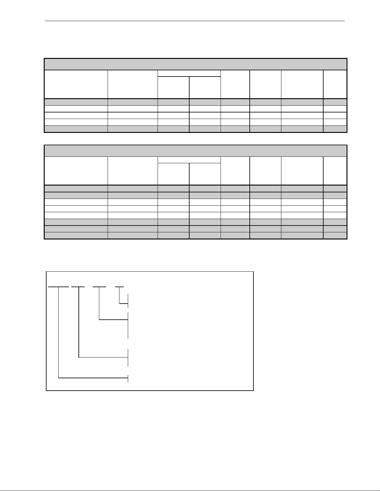
PRODUCT IDENTIFICATION CODE
Dimensions
WxHxD
[mm]
Dimensions
WxHxD
[mm]
Weight
[kg]
Weight
[kg]
COMP 400 -1P1 -20
Enclosure classification
20 = IP20
Nominal power
P75 = 0.75 kW
1P1 = 1.1 kW
etc.
Supply voltage
230 = 230 Vac 1~ (208-240 Vac)
400 = 400 Vac 3~ (380-480 Vac)
Product range: COMP = SmartDrive Compact
Fig. 1. Product Identification Code
3 EN0B-0638GE51 R1009
Page 4

SmartDrive COMPACT VARIABLE FREQUENCY DRIVES
HONEYWELL EMC CLASSES AND MARKET REQUIREMENTS
Fig. 2. EMC classes in practice
1 2 3 4 5 6
EMC levels Hospital Airp or t Residential Area Commercial Light Industry Area Heavy Industry
C O O - - - -
H R R R R O O
L - - - - R R
T R (IT Network)
O = Optional, R= Required
C = EN61800-3 Category C1 (with external RFI-filter in SmartDrive COMPACT)
H = EN61800-3 Category C2 (standard in SmartDrive COMPACT)
L = EN61800-3 Category C3 (standard in Honeywell inverters >160kW)
T = EN61800-3 IT network (e.g. ships) requirements fulfilled, units can be easily converted to T-class from
standard EMC class. Instructions for this can be found from manuals which can be downloaded from
Download Center on Honeywell inverter page http://ecc.emea.honeywell.com/inverter
EN0B-0638GE51 R1009 4
Page 5

SmartDrive COMPACT VARIABLE FREQUENCY DRIVES
MECHANICAL DIMENSIONS AND MOUNTING
There are two possible ways to mount the SmartDrive Compact onto the wall; either screw or DIN-rail mounting. The mounting
dimensions are also given on the back of the inverter.
Screw mounting DIN-rail mounting
Fig. 3. Mounting with screws or DIN-rail
Mechanical size H1 H2 H3 W1 W2 W3 D1 D2
MI1 156.5 147 137.3 65.5 37.8 4.5 98.5 7
MI2 195 183 170 90 62.5 5.5 101.5 7
MI3 262.5 252.3 241.3 100 75 5.5 108.5 7
Fig. 4. Dimensions in millimeters
COOLING
Forced air flow cooling is used in all SmartDrive Compact drives. Enough free space shall be left above and below the inverter to
ensure sufficient air circulation and cooling. SmartDrive Compact products can be mounted side by side. You will find the
required dimensions for free space and cooling air in the tables below:
Mechanical size Free space above [mm] Free space below [mm]
MI1 100 50
MI2 100 50
MI3 100 50
Mechanical size Cooling air required [m3/h)
MI1 10
MI2 10
MI3 30
5 EN0B-0638GE51 R1009
Page 6

SmartDrive COMPACT VARIABLE FREQUENCY DRIVES
CABLING AND FUSES
Use cables with heat resistance of at least +70 °C. The cables and the fuses must be dimensioned according to the following
tables. The fuses function also as cable overload protection. These instructions apply only to cases with one motor and one
cable connection from the inverter to the motor. In any other case, ask the technical support for more information.
Connection Cable type
Mains cable Power cable intended for fixed installation and the specific mains voltage. Shielded cable not required.
Motor cable Power cable equipped with compact low-impedance shield and intended for the specific mains voltage.
Control cable Screened cable equipped with compact low-impedance shield (NKCABLES /Jamak, SAB/ÖZCuY-O or similar).
(power)
MI1
MI2
MI3
P75 -1P5 4,8 – 7,0 20 2 x 2,5 + 2,5 1,5 – 4 1,5 – 4 0,5 – 1,5 0,5 – 1,5
(power)
MI1
MI2
MI3
P55 - P75 1,9 – 3,3 6 3 x 1,5 + 1,5 1,5 – 4 1,5 – 4 0,5 – 1,5 0,5 – 1,5
1P1 - 2P2 4,3 – 5,6 10 3 x 1,5 + 1,5 1,5 – 4 1,5 – 4 0,5 – 1,5 0,5 – 1,5
3P0 - 5P5 7,6 - 12 20 3 x 2,5 + 2,5 1,5 – 6 1,5 – 6 0,5 – 1,5 0,5 – 1,5
Fig. 5. SmartDrive Compact power connections
(NKCABLES/MCMK or similar recommended)
(NKCABLES /MCCMK, SAB/ÖZCUY-J or similar recommended). 360º grounding of both motor and FC
connection required to meet the standards.
Cable and fuse sizes for 208-240 V 1~/3~ inverters (COMP230-…)
Main
terminal
[mm2]
Terminals cable size (min/max) Size Type
Earth
terminal
[mm2]
Control
terminal
[mm2]
Relay
terminal
[mm2]
IN
[A]
P37 1,7 – 3,7 10 2 x 1,5 + 1,5 1,5 – 4 1,5 – 4 0,5 – 1,5 0,5 – 1,5
2P2 9,6 32 2 x 6 + 6 1,5 – 6 1,5 – 6 0,5 – 1,5 0,5 – 1,5
Fuse
[A]
Mains cable Cu
[mm2]
Cable and fuse sizes for 380-400 V 3~ inverters (COMP400-…)
Main
terminal
[mm2]
Terminals cable size (min/max) Size Type
Earth
terminal
[mm2]
Control
terminal
[mm2]
MOTOR MAINS
Relay
terminal
[mm2]
IN
[A]
MAINS MOTOR
Fuse
[A]
Mains cable Cu
[mm2]
Mechanical size MI1 Mechanical size MI2-3
EN0B-0638GE51 R1009 6
Page 7

SmartDrive COMPACT VARIABLE FREQUENCY DRIVES
Fig. 6. SmartDrive Compact control connections wiring
Fig. 7. SmartDrive Compact control connection terminals
The table below shows the SmartDrive Compact control connections with the terminal numbers.
Terminal Signal Factory setting Description
1
+10Vre Ref. Voltage output Max. load 10 mA
2
AI1 Analog signal in 1
3
GND I/O signal ground
6
24Vout 24V output for DI’s ±20%, max. load 50 mA
7
GND I/O signal ground
8
DI1 Digital Input 1
9
DI2 Digital Input 2
10
DI3 Digital Input 3
A
A RS485 signal A Fieldbus communication Modbus RTU
B
B RS485 signal B Fieldbus communication Modbus RTU
4
AI2 Analog signal in 2
5
GND I/O signal ground
13
GND I/O signal ground
14
DI4 Digital Input 4
15
DI5 Digital Input 5
16
DI6 Digital Input 6
18
AO Analog signal out
20
DO Digital signal out
22
RO11
23
RO12
24
RO21
25 RO22
26 RO23
(P) = programmable function, see parameter lists in SmartDrive Compact manuals
Control cable
tightening
torque: 0.4 Nm
Strip the plastic
cable coating for
360° grounding
Relay out1
Relay out2
Speed reference (P)
Start forward (P)
Start reverse (P)
Preset speed B0 (P)
PI actual value (P)
Preset speed B1 (P)
Fault reset (P)
Disable PI control (P)
Output frequency (P)
Active = READY (P)
Active = RUN (P)
Active = FAULT (P)
0 - +10 V , Ri = 200k
0 - +30 V Ri = 12 k (min)
0 - +30 V Ri = 12 k (min)
0 - +30 V Ri = 12 k (min)
0(4)-20 mA, Ri= 200
0 - +30 V Ri = 12 k (min)
0 - +30 V Ri = 12 k (min)
0 - +30 V Ri = 12 k (min)
0(4)-20 mA, RL= 500
Open collector, max. load 48V/50 mA
Max. switching load:
250 Vac / 2 A or 250 Vdc / 0.4 A
Max. switching load:
250 Vac / 2 A or 250 Vdc / 0.4 A
7 EN0B-0638GE51 R1009
Page 8

SmartDrive COMPACT VARIABLE FREQUENCY DRIVES
FEATURES / FUNCTIONS
Easy to set-up features
Feature Functions Benefit
Similar Start-up wizard as in Honeywell NXL HVAC inverters.
Simple 4 step wizard for specific applications
1. Activate wizard by pressing stop for 5 seconds
30 s Start-up wizard
“Keypad – Remote”
Operation
Quick Setup Menu
Parameter
upload/download with
COMP-LOADER
2. Tune the motor nominal speed
3. Tune the motor nominal current
4. Select mode (0=basic, 1= Fan, 2 = Pump and 3 =
Conveyor)
Push the navigation wheel for 5 seconds to move from remote
control (I/O or Fieldbus) to manual mode and back.
Only the most commonly used parameters visible in basic view to
provide easier navigation. The full view can be seen after P13.1
Parameter conceal is deactivated by changing the value to 0.
Parameter sets can be uploaded and downloaded with this tool.
The SmartDrive Compact does not have to be powered up since
the tool works with a 9V battery.
Compact and robust design with easy installation
Feature Functions Benefit
Compact size
Integrated RFI-filters
Single power rating
Max. ambient temperature
+50 °C
Side by side mounting
with screws or DIN-rail as
standard
Very compact size of the product compared to other similar
products from the market place
The units comply with EN61800-3 category C2 as standard. This
level is the required level for public electricity networks such as
buildings.
Single power suitable for both pump and fan or machine
applications
High maximum ambient operating temperature
SmartDrive Compact can be mounted side by side with no space
between the units either with screws or on DIN-rail as standard.
Dimensions for screw mounting can be found also on the back of
the inverter.
Fully configured inverter for
the application in question
Ready to accept 0-10V
analog speed signal in just
30 seconds
Single button operation to
change the control to manual
(keypad) and back. Useful
function when
commissioning and testing
applications
Easy navigation through the
most common parameters
Parameter copying easily
from 1 inverter to another
without even powering up the
products.
Easy download of parameter
sets created with PC-tool
Space savings
Easy selection and
installation of products.
Space savings
Cost savings
Easy selection
Flexibility
Flexibility
Uninterruptible operation
Easy installation
Space savings
EN0B-0638GE51 R1009 8
Page 9

SmartDrive COMPACT VARIABLE FREQUENCY DRIVES
Uninterruptible operation functions
Feature Functions Benefit
Overtemperature
ride-through
Power ride-through
Auto restart function
Automatically adjusts switching frequency to adapt to unusual
increase in ambient
Automatically lowers motor speed to adapt to sudden voltage
drop such as power loss
Auto restart function can be configured to make VFD restart
automatically once fault is addressed
Uninterruptible operation
Uninterruptible operation
Uninterruptible operation
VFD and motor control features
Feature Functions Benefit
Improved performance
Flying start
High switching frequency
Inbuilt PI- controller
Ability to get an already spinning fan under speed control
Honeywell SmartDrive COMPACT is capable of providing the
maximum power with high switching frequency.
Capability to make a standalone system with sensor connected
straight to the inverter and inverter doing the complete PIcontrol.
Important in clean room
production to ensure the
standard conditions
Low audible noise from the
motor
Cost saving
OPTIONAL ACCESSORIES
Option Order type code
IP21 enclosure upgrade kit for size MI1
IP21 enclosure upgrade kit for size MI2
IP21 enclosure upgrade kit for size MI3
SmartDrive Compact Parameter download/upload and PC interface tool with
SMARTDRIVE-USBC 3.0m USB-cable for PC connection
SmartDrive Compact Parameter download/upload without cable
SmartDrive 3.0m USB PC connection cable
COMP-IP21-KIT1
COMP-IP21-KIT2
COMP-IP21-KIT3
COMP-LOADER
COMP-LOADER-NC
SMARTDRIVE-USBC
9 EN0B-0638GE51 R1009
Page 10

SmartDrive COMPACT VARIABLE FREQUENCY DRIVES
Manufactured for and on behalf of the Environmental and Combustion Controls Division of Honeywell Technologies Sàrl, Rolle, Z.A. La Pièce 16, Switzerland by its Authorized Representative:
Automation and Control Solutions
Honeywell GmbH
Böblinger Strasse 17
71101 Schönaich
Germany
Phone: (49) 7031 63701
Fax: (49) 7031 637493
http://ecc.emea.honeywell.com
Subject to change without notice. Printed in Germany
EN0B-0638GE51 R1009
 Loading...