

Page 1
BA295I
Einbauanleitung • Installation instruction • Notice de montage
Instrukcja montażu
T
Anleitung zum späteren Gebrauch aufbewahren!
Keep instructions for later use!
Conserver la notice pour usage ultérieur!
Zachowa instrukcj do pózniejszego wykorzystania!
EB-BA295I Rev. A
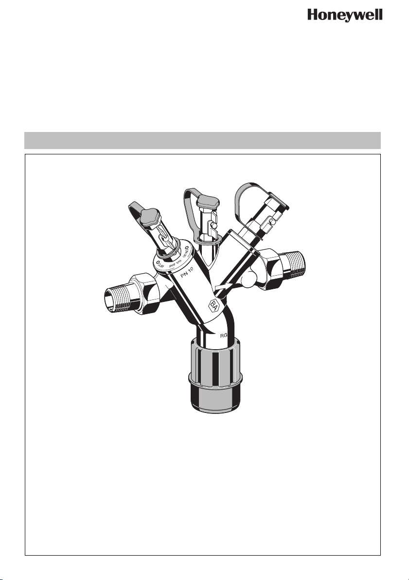
Systemtrenner
Backflow Preventer
Disconnecteur
Zespół odcinający
Page 2

D
1. Sicherheitshinweise
1. Beachten Sie die Einbauanleitung.
2. Benutzen Sie das Gerät
• bestimmungsgemäß
• in einwandfreiem Zustand
• sicherheits- und gefahrenbewusst.
3. Beachten Sie, dass das Gerät ausschließlich für
den in dieser Einbauanleitung genannten Verwendungsbereich bestimmt ist. Eine andere oder
darüber hinausgehende Benutzung gilt als nicht
bestimmungsgemäß.
4. Beachten Sie, dass alle Montage-, Inbetriebnahme,
Wartungs- und Justagearbeiten nur durch autorisierte Fachkräfte ausgeführt werden dürfen.
5. Lassen Sie Störungen, welche die Sicherheit beeinträchtigen können sofort beseitigen.
2. Funktionsbeschreibung
Systemtrenner vom Typ BA sind in 3 Druckzonen
unterteilt. In Zone ist der Druck höher als in Zone
und dort wieder höher als in Zone . An Zone
ist ein Ablassventil angeschlossen, welches spätestens dann öffnet, wenn der Differenzdruck zwischen
Zone und auf 0,14 bar abgesunken ist. Das
Wasser aus Zone strömt ins Freie. Damit ist die
Gefahr eines Rückdrückens oder Rücksaugens in das
Versorgungsnetz ausgeschlossen. Die Rohrleitung ist
unterbrochen und das Trinkwassernetz gesichert.
3. Verwendung
Medium Wasser
Maximaler
Eingangsdruck
Mindesteingangsdruck 1.5 bar
10.0 bar
4. Technische Daten
Einbaulage waagrecht mit Ablassventil nach
Max.
Betriebstemperatur
Ablaufrohranschluss
Anschlussgröße1/2" - 2"
unten
65°C
1
DN50 bei Anschlussgröße
DN70 bei Anschlussgröße 11/4" - 2"
/2" - 1"
5. Lieferumfang
Der Systemtrenner besteht aus:
• Gehäuse
• Intergrierter Schmutzfänger, Maschenweite ca.
0,6 mm
• Kartuscheneinsatz mit integriertem Rückflussverhinderer und Ablassventil
• Rückflussverhinderer ausgangsseitig
• 3 Kugelhähne zum Anschluss eines Differenzdruckmanometers
• Ablaufanschluss
6. Varianten
BA295I-... A = Standardausführung mit Anschlussver-
schraubungen
7. Montage
7.1 Einbauhinweise
• Vor und nach dem Systemtrenner Absperrventile
vorsehen
• Einbau in waagrechte Rohrleitung mit Ablassventil
nach unten
• Auf gute Zugänglichkeit achten
o Vereinfacht Wartung und Inspektion
• Im Systemtrenner ist ein Schmutzfänger integriert,
daher muss kein separater Schmutzfänger vorgesehen werden
• Der Einbau darf nicht in Räumen erfolgen, die überflutet werden können
• Der Einbauort muss frostsicher und gut belüftet sein
• Ablaufleitung mit ausreichender Kapazität vorsehen
Verwendung und Einbauart entsprechen
DIN EN 1717 / Einbauart 2
7.2 Montageanleitung
1. Rohrleitung gut durchspülen
2. Systemtrenner einbauen
• Einbau in waagrechte Rohrleitung mit Ablaufanschluss nach unten
• Durchflussrichtung beachten (Pfeilrichtung)
o spannungs- und biegemomentfrei einbauen
• Beruhigungsstrecke von 5xDN hinter Systemtrenner vorsehen
3. Ablaufleitung an Ablaufanschluss anschließen
(Kunststoffrohr HT 50)
4. Gerät ist betriebsbereit
MU1H-1234GE23 R1106 2 Honeywell GmbH
Page 3
D
8. Instandhaltung
Wir empfehlen einen Wartungsvertrag mit
einem Installationsunternehmen abzuschließen
6. Kartuscheneinsatz und Nutring entnehmen und
ersetzen
• Kartuscheneinsatz nicht in Einzelteile
zerlegen!
Instandhaltung von Systemtrennern darf nur
durch autorisiertes Fachpersonal erfolgen!
7. Montage in umgekehrter Reihenfolge
o Kartusche eindrücken bis sie einrastet
8.1 Inspektion
• Intervall: alle 6 Monate (abhängig von den
örtlichen Bedingungen)
• Durchführung durch ein Installationsunternehmen
• Inspektion mit Prüfgerät und Wartungsset
(siehe Zubehör)
8.1.1 Funktionskontrolle Ablassventil
Funktionskontrolle mit Prüfgerät TKA295 oder
TK295
8. Funktion überprüfen (siehe Kapitel Inspektion)
8.2.2 Rückflussverhinderer
1. Absperrarmatur eingangsseitig schließen
2. Ausgangsseite druckentlasten (z.B. durch Wasserzapfen).
3. Absperrarmatur ausgangsseitig schließen
4. Kugelhahn abschrauben
5. Abdeckung abschrauben
6. Rückflussverhinderer ersetzen
Rückflussverhinderer wird bei Demontage
zerstört.
1. Vorgehensweise laut Bedienungsanleitung Prüfgerät TKA295 bzw. TK295
Schnellprüfung der Funktion des Ablassventils:
• Vordruck absenken
o öffnet das Ablassventil (d.h. es tropft), so
ist die Funktion in Ordnung
8.1.2 Funktionskontrolle ausgangsseitiger Rückflussverhinderer
Funktionskontrolle mit Prüfgerät TKA295 oder
TK295
1. Vorgehensweise laut Bedienungsanleitung Prüf-
gerät TKA295 bzw. TK295
8.2 Wartung
Wir empfehlen einen Wartungsvertrag mit
einem Installationsunternehmen abzuschließen
Entsprechend DIN EN 1717 muss eine regelmäßige
Wartung durchgeführt werden.
Intervall: 1-3 Jahre (abhängig von den örtlichen
Bedingungen)
Durchführung durch ein Installationsunternehmen.
8.2.1 Kartuscheneinsatz
1. Absperrarmatur eingangsseitig schließen
2. Ausgangsseite druckentlasten (z.B. durch Wasser-
zapfen).
3. Absperrarmatur ausgangsseitig schließen
7. Funktion überprüfen (siehe Kapitel Inspektion)
8.3 Reinigung
• Durchführung durch ein Installationsunternehmen
• Durchführung durch den Betreiber
Bei Bedarf kann der Kartuscheneinsatz gereinigt
werden.
Zum Reinigen der Kunststoffteile keine
lösungsmittel- und alkoholhaltige Reinigungsmittel benutzen!
Es dürfen keine Reinigungsmittel in die Umwelt
oder Kanalisation gelangen!
1. Absperrarmatur eingangsseitig schließen
2. Ausgangsseite druckentlasten (z.B. durch Wasserzapfen).
3. Absperrarmatur ausgangsseitig schließen
4. Kugelhahn abschrauben
5. Abdeckung abschrauben
6. Kartuscheneinsatz und Nutring entnehmen und
reinigen
• Kartuscheneinsatz nicht in Einzelteile
zerlegen!
7. Montage in umgekehrter Reihenfolge
o Kartusche eindrücken bis sie einrastet
8. Funktion überprüfen (siehe Kapitel Inspektion)
4. Kugelhahn abschrauben
5. Abdeckung abschrauben
Honeywell GmbH 3 MU1H-1234GE23 R1106
Page 4
D
9. Entsorgung
• Gehäuse aus Edelstahl
• Kartuscheneinsatz aus hochwertigem Kunststoff
• Rückflussverhinderer aus hochwertigem Kunststoff
bzw. Edelstahl
• Kugelhähne aus Edelstahl
• Dichtelemente aus NBR und EPDM
• Ablaufanschluss aus hochwertigem Kunststoff
Die örtlichen Vorschriften zur ordnungsgemäßen Abfallverwertung bzw. Beseitigung
beachten!
10. Störungen / Fehlersuche
Störung Ursache Behebung
Ablassventil öffnet ohne ersichtlichen Grund
Ablassventil schließt nicht Ablagerungen am Ventilsitz Kartuscheneinsatz ausbauen und reinigen
Zu geringer Durchfluss Eingangsseitiger Schmutzfänger ist
Druckschläge im Wassernetz Vor Systemtrenner einen Druckminderer
einbauen
Schwankender Vordruck Vor Systemtrenner einen Druckminderer
einbauen
Kartuscheneinsatz ist verschmutzt Kartuscheneinsatz ausbauen und reinigen
oder ersetzen
Beschädigter O-Ring Kartuscheneinsatz ausbauen und ersetzen
Undichtes Ablassventil Kartuscheneinsatz ausbauen und reinigen
oder ersetzen
Schmutzfänger ausbauen und reinigen
verstopft
MU1H-1234GE23 R1106 4 Honeywell GmbH
Page 5
D
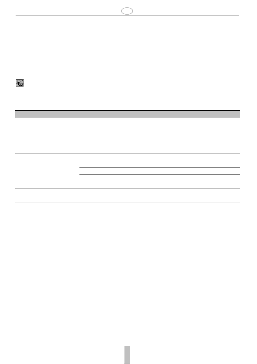
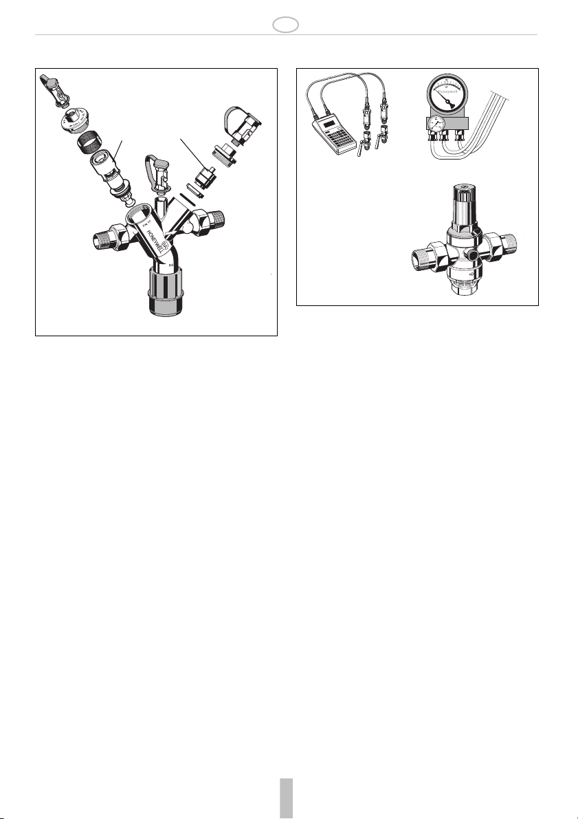
11. Ersatzteile 12. Zubehör
1
2
1 Kartuscheneinsatz1/2" - 1" KE295I-1/2
komplett 1
2 Rückflussverhin-
derereinsatz
1
/4" - 2" KE295I-11/4
1
/2" - 1" RV295I-1/2
1
1
/4" - 2" RV295I-11/4
komplett
TK295
TKA295
D06F Druckminderer
Schallschutz-Druckminderer mit Einstellskala
Vordruck max. 16 bar mit Klarsichtsiebtasse,
25 bar mit Messingsiebtasse, Hinterdruck
1,5 - 6 bar
A = Klarsichtsiebtasse bis 40°C / 16 bar
B = Messingsiebtasse bis 70°C / 25 bar
TK295 Druck-Prüfset
Elektronisches Druckmessgerät mit Digitalanzeige, Batterie betrieben.
Mit Koffer und Zubehör, ideal zur Inspektion
und Wartung der Systemtrenner BA.
TKA295Druck-Prüfset
Elektronisches Druckmessgerät mit
Differenzdruckanzeige.
Mit Koffer und Zubehör, ideal zur Inspektion
und Wartung der Systemtrenner BA.
D06F
MU1H-1234GE23 R1106 5 Honeywell GmbH
Page 6

GB
1. Safety Guidelines
1. Follow the installation instructions.
2. Use the appliance
• according to its intended use
• in good condition
• with due regard to safety and risk of danger.
3. Note that the appliance is exclusively for use in the
applications detailed in these installation instructions. Any other use will not be considered to comply
with requirements and would invalidate the
warranty.
4. Please take note that any assembly, commissioning, servicing and adjustment work may only be
carried out by authorized persons.
5. Immediately rectify any malfunctions which may
influence safety.
2. Functional description
BA type backflow preventers are divided into three
pressure zones. The pressure in zone is higher than
in zone , which in turn is higher than in zone . A
discharge valve is connected to zone which opens
at the latest when the differential pressure between
zones and falls to 0.14 bar. The water from zone
discharges to atmosphere. In this way the danger of
back pressure or back syphonage into the supply
network is prevented. The pipework connection is
interrupted and the drinking water network is
protected.
3. Application
Medium Water
Maximum inlet
pressure
Minimum inlet pressure 1.5 bar
10.0 bar
4. Technical data
Installation position
Max. operating
temperature
Discharge pipe
connection
Connection size1/2" - 2"
Horizontal with discharge valve
downwards
65°C
1
DN50 for connection sizes
DN70 for connection sizes 1
/2" - 1"
1
/4" - 2"
5. Scope of delivery
The backflow preventer consists of:
• Housing
• Integral strainer, mesh size approx. 0.6 mm
• Valve cartridge with integral check valve and
discharge valve
• Outlet check valve
• Three ball valves for the connection of a differential
pressure gauge
• Discharge connection
6. Options
BA295-... A = Standard version with connections
7. Assembly
7.1 Installations Guidelines
• Install shutoff valves before and after backflow
preventer
• Install in horizontal pipework with the discharge
valve downwards
• Ensure good access
o Simplifies maintenance and inspection
• Backflow preventers of this type have an integral
strainer which protects the device from the ingress
of dirt
• Do not install in places where flooding can occur
• The installation environment should be protected
against frost and ventilated well
• Install discharge pipework which has adequate
capacity
Use and type of installation according to DIN
EN 1717 / installation type 2
7.2 Assembly instructions
1. Thoroughly flush pipework
2. Install backflow preventer
• Install in horizontal pipework with discharge connection directed downwards
• Note flow direction (indicated by arrow)
o Install without tension or bending stresses
• Provide a straight section of pipework of at least five
times the nominal valve size after the backflow
preventer
3. Attach drain pipe to discharge connection (plastic
pipe HT 50)
4. The appliance is ready for use
MU1H-1234GE23 R1106 6 Honeywell GmbH
Page 7
GB
8. Maintenance
We recommend a planned maintenance
contract with an installation company
Maintenance of backflow preventer must be
carried out by authorized personnel!
8.1 Inspection
• Frequency: every 6 month (depending on
local operating conditions)
• To be carried out by an installation company
• Inspection with a test control unit and maintenance-set (see accessories)
8.1.1 Testing discharge valve
Take note of the instructions of the test control
unit TKA295 or TK295
1. Procedure according to instruction of the test control
unit TKA295 resp. TK295
Quick test for the discharge valve:
• Lower the inlet pressure
o if the discharge valve opens (it drops), the
function is o.k.
8.1.2 Testing outlet check valve
Take note of the instructions of the test control
unit TKA295 or TK295
1. Procedure according to instruction of the test control
unit TKA295 resp. TK295
8.2 Maintenance
We recommend a planned maintenance
contract with an installation company
In accordance with DIN EN 1717 a regular maintenance must be taken.
Frequency: every 1-3 years (depending on local
operating conditions)
To be carried out by an installation company
8.2.1 Cartridge insert
1. Close shut off valve on inlet
2. Release pressure on outlet side (e.g. through water
tap)
1. Close shut off valve on outlet
2. Remove ball valve
3. Remove cover
4. Replace cartridge insert and lip seal
• Don’t disassemble cartridge insert to individual parts!
5. Reassemble in reverse order
o push down the cartridge insert till it snaps in
6. Test function (see chapter inspection)
8.2.2 Check valve
1. Close shut off valve on inlet
2. Release pressure on outlet side (e.g. through water
tap)
1. Close shut off valve on outlet
2. Remove ball valve
3. Remove cover
4. Exchange check valve
Check valve will be destroyed after demounting
5. Test function (see chapter inspection)
9. Cleaning
• To be carried out by an installation company
• To be carried out by the operator
If necessary, the cartridge insert can be cleaned.
Do not use any cleaning agents containing
solvents or alcohol to clean the plastic parts!
Detergents must not be allowed to enter the
environment or the sewerage system!
1. Close shut off valve on inlet
2. Release pressure on outlet side (e.g. through water
tap)
1. Close shut off valve on outlet
2. Remove ball valve
3. Remove cover
4. Clean or replace cartridge insert and lip seal
• Don’t disassemble cartridge insert to individual parts!
5. Reassemble in reverse order
o push down the cartridge insert till it snaps in
6. Test function (see chapter inspection)
Honeywell GmbH 7 MU1H-1234GE23 R1106
Page 8

GB
10. Disposal
• Stainless steel housing
• High-quality synthetic material valve cartridge
• High-quality synthetic material or stainless steel
check valves
• Stainless steel ball valves
• Seals in NBR and EPDM
• High quality synthetic material discharge connection
11. Troubleshooting
Störung Ursache Behebung
Discharge valve opens without
apparent reason
Discharge valve don’t close Deposits on valve seat Remove cartridge insert and clean or
Flow is to low Inlet strainer is blocked Remove strainer and clean it
Pressure strokes in water supply
system
Install a pressure reducing valve upstream
the backflow preventer
Fluctuating inlet pressure Install a pressure reducing valve upstream
the backflow preventer
Cartridge insert is contaminated Remove cartridge insert and exchange it
exchange it
Damaged ’o’ring Remove cartridge insert and exchange it
Leaky discharge valve Remove cartridge insert and clean or
exchange it
MU1H-1234GE23 R1106 8 Honeywell GmbH
Page 9

GB
12. Spare Parts 13. Accessories
1
2
1 Cartridge insert1/2" - 1" KE295I-1/2
complete 1
1
/4" - 2" KE295I-11/4
2 Check valve insert1/2" - 1" RV295I-1/2
complete 1
1
/4" - 2" RV295I-11/4
TK295
TKA295
D06F Pressure reducing valve
Noise protected pressure reducing valve with
setting scale. Maximum inlet pressure 16 bar,
with brass filter bowl 25 bar, outlet pressure
range 1.5 - 6.0 bar
A = With clear filter bowl up to 40 °C / 16 bar
B = With brass filter bowl up to 70 °C / 25 bar
TK295 Test kit
Electronic pressure measuring device with
digital indicator, runs by a battery.
With case and accessories, ideal for inspection and maintenance of backflow preventer
type BA.
TKA295Test kit
Analogue pressure measuring device with
differential pressure display.
With case and accessories, ideal for inspection and maintenance of backflow preventer
type BA.
D06F
MU1H-1234GE23 R1106 9 Honeywell GmbH
Page 10

F
1. Consignes de sécurité
1. Suivre les indications de la notice de montage.
2. En ce qui concerne l'utilisation de l'appareil
• Utiliser cet appreil conformément aux données
constructeur
• Maintenir l'appareil en parfait état
• Respectez les consignes de sécurité
3. Il faut noter que cet équipement ne peut être mis en
oeuvre que pour les conditions d'utilisation mentionnées dans cette notice. Toute autre utilisation, ou
le non respect des conditions normales d'utilisation,
serait considérée comme non conforme.
4. Observer que tous les travaux de montage, de mise
en service, d'entretien et de réglage ne pourront
être effectués que par des spécialistes autorisés.
5. Prendre des mesures immédiates en cas d'anomalies mettant en cause la sécurité.
2. Description fonctionnelle
Les disconnecteurs de type BA sont divisés en 3 zones
de pression. Dans la zone la pression est plus
élevée que dans la zone où elle est encore plus
élevée que dans la zone . A la zone une soupape
de vidange est raccordée et elle s'ouvre au plus tard
lorsque la pression différentielle entre la zone et
est tombée à 0,14 bar. L'eau de la zone s'écoule
vers l'extérieur. Ainsi, le risque de retour ou de réaspiration dans le réseau de distribution est exclu. La
tuyauterie est interrompue et le réseau d'eau potable
est protégé.
3. Mise en oeuvre
Medium Eau
Pression d'admission
maximale
Pression d'admission
minimale
10.0 bar
1.5 bar
4. Caractéristiques
Position de
montage
Température de
service maxi
Raccord du tuyau
de décharge
Dimensions de
raccordement
horizontale, raccord de sortie vers le
bas
65°C
DN50 pour une dimension de
raccordement de 1/2" - 1"
DN70 pour une dimension de
raccordement de 11/4" - 2"
1
/2" - 2"
5. Contenu de la livraison
Le disconnecteur comprend:
• Corps
• Panier filtrant intégré, ouverture 0.6 mm
• Cartouche avec clapet anti-retour et soupape de
vidange intégrés
• Clapet anti-retour côté sortie
• 3 robinets à boisseau sphérique pour le raccordement d’un manomètre de pression différentielle
• Raccordement de sortie
6. Variantes
BA295I-... A = Modèle standard avec raccords de
connexion
7. Montage
7.1 Dispositions à prendre
• Prévoir une valve d'arrêt avant et après le séparateur du système
• Montage dans les conduites horizontales avec une
valve d'écoulement vers le bas
• Veillez à un accès facile
o Simplifie la maintenance et l'inspection
• Un panier filtrant est intégré au disconnecteur, il
n'est donc pas nécessaire de monter un filtre à part.
• Le montage ne doit pas se faire dans des locaux qui
peuvent être innondés
• Le lieu de montage doit être protégé du gel et bien
aéré
• Prévoir une conduite de sortie avec suffisamment
de capacité
Utilisation et type de montage selon la norme
DIN EN 1717 / type de montage 2
7.2 Instructions de montage
1. Bien rincer la conduite
2. Monter le séparateur de système
• Montage dans une conduite horizontale avec
raccord de sortie vers le bas
• Veillez à la direction de l'écoulement (direction de la
flèche)
o Vérifier l'absence de contraintes anormales en
traction et en flexion
• Prévoir un trajet de repos de 5xDN derrière le séparateur du système
3. Raccorder la conduite de sortie au raccordement
(tuyau en plastique HT 50)
4. L'appareil est opérationnel.
MU1H-1234GE23 R1106 10 Honeywell GmbH
Page 11

F
8. Maintenance
Nous recommandons de conclure un contrat
d'entretien avec un installateur
5. Dévisser le couvercle
6. Retirer la cartouche et la bague et rempalcer
• Ne pas démonter la cartouche !
La remise en état du séparateur de système
doit être réalisée uniquement par du personnel
qualifié et autorisé !
8.1 Inspection
• Intervalle : tous les 6 mois (en fonction des
conditions locales)
• Réalisation par une entreprise d'installation
• Inspection avec appareil de contrôle et kit
d'entretien (voir Accessoires)
8.1.1 Contrôle du fonctionnement de la valve
d'écoulement
Contrôle du fonctionnement avec l'appareil
TKA295 ou TK295
7. Montage dans l'ordre inverse
o Appuyer sur la cartouche jusqu'à ce qu'elle
s'enclenche.
8. Contrôler le fonctionnement (voir chapitre Inspection)
8.2.2 Clapet anti-retour
1. Fermer la robinet de fermeture du côté de l'entrée
2. Dépressuriser le côté sortie (ouverture du robinet de
purge, etc.).
3. Fermer le robinet de fermeture du côté sortie
4. Dévisser le robinet à boisseau sphérique
5. Dévisser le couvercle
6. Remplacer le clapet anti-retour
1. Procédure selon les instructions de service de
l'appareil TKA295 ou TK295
Contrôle rapide du fonctionnement de la
soupape de vidange :
• Réduire la pression d'admission
o si la soupape de vidange s'ouvre (des
gouttes sortent), le fonctionnement est
correct.
8.1.2 Contrôle du fonctionnement clapet antiretour du côté de la sortie
Contrôle du fonctionnement avec l'appareil
TKA295 ou TK295
1. Procédure selon les instructions de service de
l'appareil TKA295 ou TK295
8.2 Maintenance
Nous recommandons de conclure un contrat
d'entretien avec un installateur
Conformément à la DIN EN 1717, une maintenance
régulière soit être réalisée.
Périodicité: tous les 1 à 3 ans en fonction des
conditions d'exploitation
Opération effectuée par un professionnel
Le clapet anti-retour est détruit lors du démontage.
7. Contrôler le fonctionnement (voir chapitre Inspection)
8.3 Nettoyage
• Réalisation par une entreprise d'installation
• Réalisation par l'exploitant
En cas de besoin, la cartouche peuve être nettoyé.
Ne pas utiliser de détergents contenant des
solvants ou de l'alcool pour nettoyer les parties
en plastique!
Ne pas rejeter de produit détergent dans l'environnement ou dans les canalisations!
1. Fermer la robinet de fermeture du côté de l'entrée
2. Dépressuriser le côté sortie (ouverture du robinet de
purge, etc.).
3. Fermer le robinet de fermeture du côté sortie
4. Dévisser le robinet à boisseau sphérique
5. Dévisser le couvercle
6. Retirer la cartouche et la bague et nettoyer
• Ne pas démonter la cartouche !
8.2.1 Utilisation de cartouches
1. Fermer la robinet de fermeture du côté de l'entrée
2. Dépressuriser le côté sortie (ouverture du robinet de
purge, etc.).
3. Fermer le robinet de fermeture du côté sortie
4. Dévisser le robinet à boisseau sphérique
Honeywell GmbH 11 MU1H-1234GE23 R1106
7. Montage dans l'ordre inverse
o Appuyer sur la cartouche jusqu'à ce qu'elle
s'enclenche.
8. Contrôler le fonctionnement (voir chapitre Inspection)
Page 12

F
9. Matériel en fin de vie
• Boîtier en acier inoxydable
• Cartouche en matière synthétique de haute qualité
• Clapet anti-retour en matière synthétique ou en
acier inoxydable de haute qualité
• Robinets à boisseau sphérique en acier inoxydable
• Eléments d'étanchéité en NBR et EPDM
• Raccordement de sortie en matière synthétique de
qualité supérieure
Se conformer à la réglementation pour l'élimination des équipements industriels en fin de vie
vers les filières de traitement autorisées!
10. Défaut / recherche de panne
Panne Cause Remède
La soupape de vidange s'ouvre
sans raison manifeste
La soupape de vidange ne
ferme pas.
Débit trop faible Le panier filtrant côté entrée est
Coups de pression dans le réseau
d'eau
Monter un manodétendeur en amont du
disconnecteur
Variations de la pression d'admission Monter un manodétendeur en amont du
disconnecteur
Cartouche sale Retirer la cartouche et la nettoyer.
Dépôts sur le siège de soupape Démonter la cartouche et la nettoyer ou
remplacer.
Joint torique endommagé Retirer la cartouche et la remplacer.
Fuites à la soupape de vidange Démonter la cartouche et la nettoyer ou
remplacer.
Retirer le panier filtrant et le nettoyer.
bouché.
MU1H-1234GE23 R1106 12 Honeywell GmbH
Page 13

F
11. Pièces de rechange 12. Accessoires
1
1 Cartouche
2
1
/2" - 1" KE295I-1/2
1
1
/4" - 2" KE295I-11/4
2 Clapet anti-retour1/2" - 1" RV295I-1/2
1
1
/4" - 2" RV295I-11/4
TK295
TKA295
D06F Manodétendeur
Manodétendeur antibruit avec échelle de
réglage
Pression d’alimentation maxi. 16 bar avec pot
de décantation transparent, 25 bar avec pot
de décantation en laiton,
A = pot de décantation transparent jusqu’à
40°C / 16 bar
B = pot de décantation en laiton jusqu’à
70°C / 25 bar
TK295 Kit de contrôle de pression
Manomètre électronique avec affichage
numérique, à pile. Avec mallette et accessoires, idéal pour l'inspection et l'entretien des
disconnecteurs BA.
TKA295 Kit de contrôle de pression
Manomètre électronique avec affichage de
pression différentielle. Avec mallette et accessoires, idéal pour l'inspection et l'entretien des
disconnecteurs BA.
D06F
MU1H-1234GE23 R1106 13 Honeywell GmbH
Page 14

PL
1. Wskazówki bezpieczeDstwa
1. Przestrzegać instrukcji montażu.
2. Proszę użytkować przyrząd
• zgodnie z jego przeznaczeniem
• w nienagannym stanie
• ze świadomością bezpieczeństwa i zagrożeń
3. Proszę uwzględnić, że przyrząd przeznaczony jest
wyłącznie dla zakresu zastosowania określonego w
niniejszej instrukcji montażu. Każde inne lub
wykraczające poza to użytkowanie uznawane jest
jako niezgodne z przeznaczeniem.
4. Proszę uwzględnić, że wszystkie prace montażowe
mogą być wykonywane tylko przez autoryzowany
personel fachowy.
5. Wszystkie te zakłócenia, które mogą naruszyć
bezpieczeństwo należy natychmiast usunąć.
2. Opis funkcji
Zespół odcinający typu BA został podzielony na 3
strefy ciśnienia. W strefie ciśnienie jest wyższe niż
w strefie a tam z kolei jeszcze wyższe niż w strefie
. Do strefy podłączony został zawór spustowy
otwierający się najpóźniej w momencie, gdy różnica
ciśnień pomiędzy strefą a spadnie do 0,14 bara.
Woda ze strefy wypływa na zewnątrz. Tym samym
wykluczone zostaje niebezpieczeństwo ze strony
ciśnienia wstecznego lub zassania zwrotnego do sieci
zasilającej. Rurociąg zostaje przerwany a sieć wody
pitnej zabezpieczona.
3. Zastosowanie
Medium Woda
Maksymalne ciśnienie
wejściowe
Minimalne ciśnienie
wejściowe
10.0 bar
1.5 bar
4. Dane techniczne
Pozycja montażowa pozioma z zaworem spustowym
Maks. temperatura
pracy
Przyłącze rury
spustowej
Rozmiar przyłącza1/2" - 2"
MU1H-1234GE23 R1106 14 Honeywell GmbH
wdół
65°C
DN50 dla rozmiaru przyłącza
1
/2" - 1"
DN70 dla rozmiaru przyłącza
1
/4" - 2"
1
5. Zakres dostawy
Zespół odcinający składa się z:
• Obudowy
• Zintegrowanego osadnika zanieczyszczen,
wielkosc oczka 0,6 mm
• Wkładu kartuszowego ze zintegrowanym zaworem
przeciwzwrotnym i zaworem spustowym
• Zaworu przeciwzwrotnego na wyjściu
• 3 zawory kulowe do przyłączenia manometru
rżnicowego
• przyłącza spustowego
6. Warianty
BA295I-... A = Wersja standardowa bez złączek
gwintowanychn
7. Montaż
7.1 Zamontowanie
• Przed i za oddzielaczem systemowym należy
przewidzieć zawory odcinające
• Montaż w poziomym przewodzie rurowym
z zaworem spustowym skierowanym w dół
• Zwrócić uwagę na dobry dostęp
oUłatwia konserwację iprzeglądy
• W zespole odcinającym został zamontowany
osadnik zanieczyszczeń, zatem nie trzeba
stosować oddzielnego osadnika
• Nie można montować w pomieszczeniach, które
mogą ulec zalaniu
• Miejsce montażu musi być wolne od mrozu i dobrze
przewietrzane
• Przewidzieć przewód odpływowy o wystarczającej
pojemności
Zastosowanie i typ montażu odpowiadają DIN
EN 1717 / typ montażu 2
7.2 Instrukcja montażu
1. Dokładnie przepłukać przewód rurowy.
2. Zamontować oddzielacz systemowy
• Montaż w poziomym przewodzie rurowym
zprzyłączem spustowym skierowanym w dół
• Uważać na kierunek przepływu (kierunek strzałki)
o w stanie wolnym od naprężeń i momentów
zginających
• Za oddzielaczem systemowym przewidzieć odcinek
uspokajający o długości 5xDN
3. Podłączyć przewód spustowy do przyłącza
spustowego (rura z tworzywa sztucznego HT 50)
4. Urządzenie jest gotowe do pracy
Page 15

PL
8. Utrzymywanie w dobrym stanie
Zalecamy zawarcie umowy konserwacyjnej z
odpowiednią firmą instalacyjną
5. Odkręcić pokrywę
6. Wyjąć wkład kartuszowy z pierścieniem
rowkowanym i wymienić
• Nie rozkładać na części wkładu
Utrzymywanie oddzielaczy systemowych
kartuszowego!
wstanie sprawności może być przeprowadzane
wyłącznie przez autoryzowany personel
specjalistyczny!
8.1 Inspekcja
• Okres: co 6 miesięcy (w zależności od
panujących na miejscu warunków)
• Kontrola przeprowadzana przez firmę
instalacyjną
• Przegląd przy użyciu przyrządu kontrolnego
i zestawu do konserwacji (zob. akcesoria)
8.1.1 Działanie zaworu spustowego
Kontrola działania za pomocą przyrządu
kontrolnego TKA295 lub TK295
7. Montaż w odwrotnej kolejności
o Wciskać kartusz aż do zakleszczenia
8. Sprawdzić działanie (zob. rozdziaą Przegląd)
8.2.2 Zawór przeciwzwrotny
1. Zamknąć armaturę odcinającą po stronie wlotowej
2. Dokonać redukcji ciśnienia po stronie wyjściowej
(np. przez kurek wodny).
3. Zamknąć armaturę odcinającą po stronie wylotowej
4. Odkręcić zawr kulowy
5. Odkręcić pokrywę
6. Wymienić zawór przeciwzwrotny
Podczas demontażu układ uniemożliwiający
przepływ zwrotny ulega zniszczeniu.
1. Sposób postępowania zgodnie z instrukcją obsługi
przyrządu kontrolnego TKA295 lub TK295
Szybka kontrola działania zaworu spustowego:
• Zredukować ciśnienie wstępne
oJeśli zawór spustowy się otwiera (tzn.
kapie), to wskazuje to na prawidłowe
działanie
8.1.2 Działanie zaworu przeciwzwrotnego na
wyjściu
Kontrola działania za pomocą przyrządu
kontrolnego TKA295 lub TK295
1. Sposób postępowania zgodnie z instrukcją obsługi
przyrządu kontrolnego TKA295 lub TK295
8.2 Konserwacja
Zalecamy zawarcie umowy konserwacyjnej z
odpowiednią firmą instalacyjną
Zgodnie z DIN EN 1717 konieczna jest regularna
konserwacja.
Okres: raz w roku Przeprowadzenie przez firmę
instalacyjną
7. Sprawdzić działanie (zob. rozdziaą Przegląd)
8.3 Czyszczenie
• Kontrola przeprowadzana przez firmę
instalacyjną
• Przeprowadzane przez eksploatującego
W razie potrzeby można przeczyścić wkład
kartuszowy.
Do czyszczenia części z tworzywa sztucznego
nie używać środków do czyszczenia,
zawierających rozpuszczalniki i alkohol!
Żadne środki czyszczące nie powinny dostać
się do środowiska naturalnego lub kanalizacji!
1. Zamknąć armaturę odcinającą po stronie wlotowej
2. Dokonać redukcji ciśnienia po stronie wyjściowej
(np. przez kurek wodny).
3. Zamknąć armaturę odcinającą po stronie wylotowej
4. Odkręcić zawr kulowy
5. Odkręcić pokrywę
6. Wyjąć wk
ład kartuszowy z pierścieniem
rowkowanym i oczyścić
• Nie rozkładać na części wkładu
8.2.1 Wkład kartuszowy
kartuszowego!
1. Zamknąć armaturę odcinającą po stronie wlotowej
2. Dokonać redukcji ciśnienia po stronie wyjściowej
(np. przez kurek wodny).
3. Zamknąć armaturę odcinającą po stronie wylotowej
7. Montaż w odwrotnej kolejności
o Wciskać kartusz aż do zakleszczenia
8. Sprawdzić działanie (zob. rozdziaą Przegląd)
4. Odkręcić zawr kulowy
Honeywell GmbH 15 MU1H-1234GE23 R1106
Page 16

PL
9. Usuwanie
• Korpus ze stali szlachetnejj
• Wkład kartuszowy z wysokiej jakości tworzywa
sztucznego
• Zawory zwrotne z wysokogatunkowego tworzywa
sztucznego lub stali szlachetnej
• Zawory kulowe ze stali szlachetnej
• Elementy uszczelniające z NBR i EPDM
• Przyłącze spustowe z wysokogatunkowego
tworzywa sztucznego
10. Zakłócenia / poszukiwanie usterek
Usterka Przyczyna Usuwanie
Zawór spustowy otwiera bez
wyraźnej przyczyny
Zawór spustowy nie zamyka Osad przy przy gnieździe zaworu Wymontować i oczyścić lub wymienić wkład
Zbyt mały przepływ Osadnik zanieczyszczeń po stronie
Uderzenie ciśnienia w sieci wodnej Zainstalować przed zespołem odcinającym
reduktor ciśnienia
Zmienne ciśnienie wstępne Zainstalować przed zespołem odcinającym
reduktor ciśnienia
Wkład kartuszowy jest zabrudzony Wymontować ioczyścić wkład kartuszowy
kartuszowy
Uszkodzony pierścień typu O-ring Wymontować i wymienić wkład kartuszowy
Nieszczelny zawór spustowy Wymontować i oczyścić lub wymienić wkład
kartuszowy
Wymontować i oczyścić osadnik
wejścia jest zatkany
zanieczyszczeń
MU1H-1234GE23 R1106 16 Honeywell GmbH
Page 17

PL
11. Części zamienne 12. Wyposażenie dodatkowe
1
2
Wklad kartuszowy1/2" - 1" KE295I-1/2
1
/4" - 2" KE295I-11/4
1
WkBad zaworu
przeciwzwrotnego
1
/2" - 1" RV295I-1/2
1
/4" - 2" RV295I-11/4
1
TK295
TKA295
D06F Reduktor ciĎnienia
tor ciśnienia z izolacją akustyczną i skalą
nastawczą
Ciśnienie dolotowe maks. 16 bar z
przezroczystą obudową filtra, 25 bar z
mosiżną obudową filtra, ciśnienie wylotowe
1,5 – 6 bar
A = przezroczysta obudowa filtra do
40°C / 16 bar
B = mosiężna obudowa filtra do 70°C / 25 bar
TK295 Zestaw do kontroli ciśnienia
Elektroniczny przyrząd pomiarowy z
cyfrowym wyświetlaczem, zasilany z baterii. Z
futerałem i akcesoriami, idealny do
przeprowadzania przeglądów i konserwacji
zespołów odcinających BA.
TKA295 Zestaw do kontroli ciśnienia
Elektroniczny przyrząd pomiarowy z cyfrowym
wyświetlaniem różnicy ciśnień. Z futerałem i
akcesoriami, idealny do przeprowadzania
przeglądów i konserwacji zespołów
odcinających BA.
D06F
MU1H-1234GE23 R1106 17 Honeywell GmbH
Page 18

PL
Honeywell GmbH 18 MU1H-1234GE23 R1106
Page 19

PL
MU1H-1234GE23 R1106 19 Honeywell GmbH
Page 20

Automation and Control Solutions
Honeywell GmbH
Hardhofweg
D-74821 Mosbach
Phone: (49) 6261 810
Fax: (49) 6261 81309
http://europe.hbc.honeywell.com
www.honeywell.com
Manufactured for and on behalf of the
Environmental and Combustion Controls Division of
Honeywell Technologies Sàrl, Ecublens, Route du
Bois 37, Switzerland by its Authorised Representative
Honeywell GmbH
EN0H-1234GE23 R1106
Subject to change
© 2006 Honeywell GmbH
Page 21

7.22.
8.1.1
8.2.1 + 8.3
8.1.2
8.2.2
4.
5.
6.
4.
5.
6.
MU1H-1234GE23 R1106 Honeywell GmbH
Page 22

1. Sicherheitshinweise ........................... 2
2. Funktionsbeschreibung ..................... 2
3. Verwendung ....................................... 2
4. Technische Daten .............................. 2
5. Lieferumfang ...................................... 2
6. Varianten ............................................ 2
7. Montage ............................................. 2
8. Instandhaltung ................................... 3
9. Entsorgung ........................................ 4
10. Störungen / Fehlersuche ................... 4
11. Ersatzteile .......................................... 5
12. Zubehör .............................................. 5
1. Safety Guidelines ............................... 6
2. Functional description ....................... 6
3. Application ......................................... 6
4. Technical data ................................... 6
5. Scope of delivery ............................... 6
6. Options ............................................... 6
7. Assembly ........................................... 6
8. Maintenance ...................................... 7
9. Cleaning ............................................. 7
10. Disposal ............................................. 8
11. Troubleshooting ................................ 8
12. Spare Parts ........................................ 9
1. Consignes de sécurité ..................... 10
2. Description fonctionnelle ................10
3. Mise en oeuvre ................................10
4. Caractéristiques ............................... 10
5. Contenu de la livraison .................... 10
6. Variantes .......................................... 10
7. Montage ........................................... 10
8. Maintenance .................................... 11
9. Matériel en fin de vie .......................12
10. Défaut / recherche de panne ..........12
11. Pièces de rechange ......................... 13
12. Accessoires ...................................... 13
1. WskazÛwki bezpieczeDstwa ..........14
2. Opis funkcji ...................................... 14
3. Zastosowanie .................................. 14
4. Dane techniczne .............................. 14
5. Zakres dostawy ............................... 14
6. Warianty ........................................... 14
7. Montaø............................................. 14
8. Utrzymywanie w dobrym stanie ...... 15
9. Usuwanie ......................................... 16
10. ZakŠÛcenia / poszukiwanie usterek 16
11. CzÍúci zamienne .............................. 17
12. Wyposaøenie dodatkowe ............... 17
MU1H-1233GE23 R1106 Honeywell GmbH
 Loading...