

Honeywell BA295D-3WH, BA295D-4WH, BA295D-4WHS, BA295D-3WHS Installation Instructions Manual
Page 1
BA295D-3/4WH
BA295D-3/4WHS
Einbauanleitung Installation instructions
Anleitung zum späteren Gebrauch aufbewahren!
Keep instructions for later use!
32304684-001
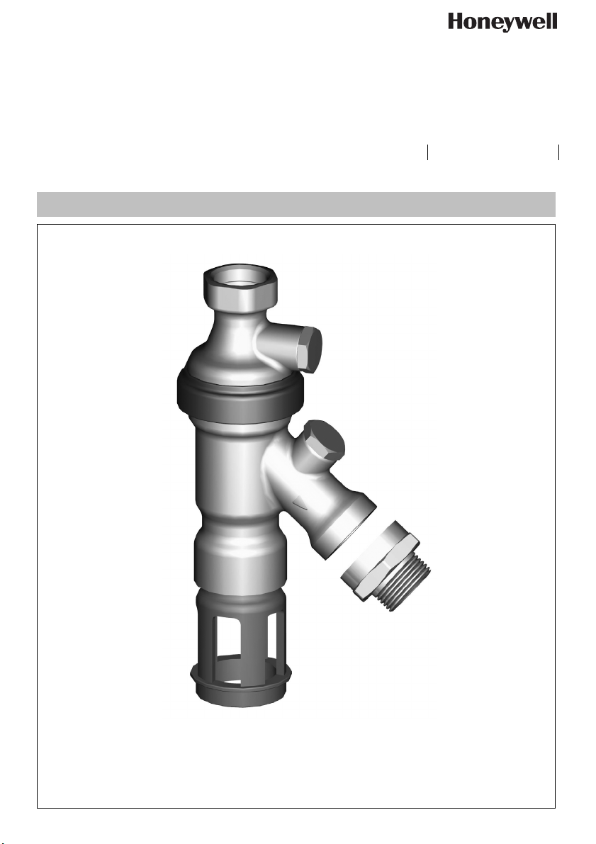
Systemtrenner
Backflow Preventer
Page 2

D
1. Sicherheitshinweise
1. Beachten Sie die Einbauanleitung.
2. Benutzen Sie das Gerät
• bestimmungsgemäß
• in einwandfreiem Zustand
• sicherheits- und gefahrenbewusst.
3. Beachten Sie, dass das Gerät ausschließlich für den in
dieser Einbauanleitung genannten Verwendungsbereich
bestimmt ist. Eine andere oder darüber hinausgehende
Benutzung gilt als nicht bestimmungsgemäß.
4. Beachten Sie, dass alle Montage-, Inbetriebnahme,
Wartungs- und Justagearbeiten nur durch autorisierte
Fachkräfte ausgeführt werden dürfen.
5. Lassen Sie Störungen, welche die Sicherheit beeinträchtigen können, sofort beseitigen.
2. Funktionsbeschreibung
Systemtrenner vom Typ BA sind in 3 Druckzonen unterteilt. In
Zone c ist der Druck höher als in Zone d und dort wieder
höher als in Zone e. An Zone d ist ein Ablassventil angeschlossen, welches spätestens dann öffnet, wenn der Differenzdruck zwischen Zone c und d auf 0,14 bar abgesunken
ist. Das Wasser aus Zone d strömt ins Freie, beide Rückflussverhinderer schließen und trennen somit Zone d von
Zone c und e. Damit ist die Gefahr eines Rückdrückens
oder Rücksaugens in das Versorgungsnetz ausgeschlossen.
Die Rohrleitung ist unterbrochen und das Trinkwassernetz
gesichert.
3. Verwendung
Medium Trinkwasser
Maximaler Eingangsdruck 10.0 bar
Mindesteingangsdruck 1.5 bar
4. Technische Daten
Einbaulage senkrecht mit Ablaufanschluss
nach unten
Max. Betriebstemperatur 65 °C
Ablaufrohranschluss DN40
Nennweite
3
/4"
5. Lieferumfang
Der Systemtrenner besteht aus:
• Gehäuseoberteil mit Prüfstutzen inkl. Verschlussstopfen
• Austauscheinheit komplett geprüft mit
- drehbarem Gehäuseunterteil mit Prüfstutzen inkl.
Verschlussstopfen
- Schmutzfänger (Maschenweite 0,5 mm)
- Kartuscheneinsatz mit integriertem Rückflussverhinderer und Ablassventil
- Rückflussverhinderer ausgangsseitig
- Halteklammer
- Plombierschellen
• Gewindeadapter
• zwei Prüfstutzen (dritter Prüfstutzen ist im Prüfadapter des
optional erhältlichen Wartungssets WS295STN integriert)
6. Varianten
BA295D-3/4WH = Standardversion mit eingangsseitig G3/4"
(ISO 228-1) Anschlussgewinde und
ausgangsseitig G1" (ISO 228-1)
Anschlussgewinde, 1" IG auf 3/4" AG
Gewindeadapter beiliegend, verchromt,
mit Ablaufanschluss
BA295D-3/4WHS =Standardversion mit eingangsseitig G1"
(ISO 228-1) Anschlussgewinde und
ausgangsseitig G1" (ISO 228-1)
Anschlussgewinde
7. Montage
7.1. Einbauhinweise
• Einbau direkt unter Verteilerkopf oder Wasserhahn mit
Ablauf nach unten
• Im Systemtrenner ist ein Schmutzfänger integriert, der
Ablagerungen aus dem Rohrleitungssystem zurückhält.
Bei stark verunreinigtem Wasser ist ein Feinfilter vorzuschalten, um die einwandfreie Funktion des Gerätes zu
gewährleisten.
• Der Einbauort muss frostsicher sein. Beim Einsatz im
Freien muss der Systemtrenner bei Frostgefahr demontiert werden.
7.2. Montageanleitung
1. Absperrventil vor der Armatur schließen
2. Einbau direkt unter Verteilerkopf oder Wasserhahn mit
Ablauf nach unten
3. Systemtrenner mit dem Zapfventil mit mitgelieferter Zapf-
hahnplombierschelle verplomben
4. Bei Bedarf 1" IG auf 3/4" AG Gewindeadapter montieren
5. Bei Einsatz im Gebäude Ablaufanschluss montieren
6. Absperrventil vor der Armatur öffnen
Honeywell GmbH 2 MU1H-1248GE23 R1114
Page 3
D
8. Instandhaltung
Wir empfehlen einen Wartungsvertrag mit einem Installationsunternehmen abzuschließen
8.1. Inspektion
Inspektion mit Prüfgerät und Wartungsset (siehe Zubehör)
• Intervall: alle 6 Monate (abhängig von den örtlichen
Bedingungen)
• Durchführung durch ein Installationsunternehmen
8.1.1. Funktionskontrolle Ablassventil
Absperrventil muss bei Funktionskontrolle maximal
geöffnet sein
Funktionskontrolle mit Prüfgerät TKA295 oder TK295
1. Prüfadapter (siehe Wartungsset) ausgangsseitig
montieren
2. Vorgehensweise laut Bedienungsanleitung Prüfgerät
TKA295 bzw. TK295
Schnellprüfung der Funktion des Ablassventils:
• Vordruck absenken
- öffnet das Ablassventil (d.h. es tropft), so ist die
Funktion in Ordnung
8.1.2. Funktionskontrolle ausgangsseitiger Rückflussverhinderer
Absperrventil muss bei Funktionskontrolle maximal
geöffnet sein
Funktionskontrolle mit Prüfgerät TKA295 oder TK295
1. Prüfadapter (siehe Wartungsset) ausgangsseitig
montieren
2. Vorgehensweise laut Bedienungsanleitung Prüfgerät
TKA295 bzw. TK295
8.2. Wartung
• Durchführung durch ein Installationsunternehmen
• Durchführung durch den Betreiber
8.2.1. BA-Funktionsteile
• Intervall: min. einmal jährlich (abhängig von den örtlichen Bedingungen)
1. Absperrventil vor der Armatur schließen
2. Systemtrenner durch leichtes Öffnen des Prüfstopfens
druckentlasten
3. Ablaufanschluss abziehen
4. Plombierschelle entfernen
5. Halteklammer lösen
6. Austauscheinheit nach unten abziehen
• Komplette Austauscheinheit ersetzen
7. Neue Austauscheinheit einstecken
8. Neue Halteklammer und Plombierschellen montieren
9. Ablaufanschluss einstecken
10. Absperrventil vor der Armatur öffnen
MU1H-1248GE23 R1114 3 Honeywell GmbH
8.3. Betriebsbedingte Wartung
8.3.1. Schmutzfänger
Bei Bedarf kann der Schmutzfänger gereinigt oder ausgetauscht werden.
1. Absperrventil vor der Armatur schließen
2. Systemtrenner durch leichtes Öffnen des Prüfstopfens
druckentlasten
3. Plombierschelle entfernen
4. Halteklammer lösen
5. Gehäuseunterteil nach unten abziehen
6. Schmutzfänger entnehmen und reinigen oder ersetzen
7. Gehäuseunterteil einstecken
8. Halteklammer und Plombierschellen montieren
9. Absperrventil vor der Armatur öffnen
8.3.2. Kartuscheneinsatz
Bei Bedarf kann der Kartuscheneinsatz gereinigt oder ausgetauscht werden.
Zum Reinigen der Kunststoffteile keine lösungsmittelund/oder alkoholhaltigen Reinigungsmittel benutzen, da
dies zu Schädigung der Kunststoffbauteile führen kann
- die Folge kann ein Wasserschaden sein!
1. Absperrventil vor der Armatur schließen
2. Systemtrenner durch leichtes Öffnen des Prüfstopfens
druckentlasten
3. Plombierschelle entfernen
4. Halteklammer lösen
5. Gehäuseunterteil nach unten abziehen
6. Kartuscheneinsatz entnehmen und reinigen oder
ersetzen
7. Kartuscheneinsatz wieder einstecken
• Kartusche eindrücken bis sie einrastet
8. Gehäuseunterteil einstecken
9. Halteklammer und Plombierschellen montieren
10. Absperrventil vor der Armatur öffnen
11. Funktion überprüfen (siehe Kapitel Inspektion)
8.3.3. Rückflussverhinderer
Bei Bedarf kann der ausgangsseitige Rückflussverhinderer
ausgetauscht werden.
1. Absperrventil vor der Armatur schließen
2. Systemtrenner durch leichtes Öffnen des Prüfstopfens
druckentlasten
3. Gewindeadapter abschrauben
4. Rückflussverhinderer entnehmen und austauschen
5. Gewindeadapter aufschrauben
6. Absperrventil vor der Armatur öffnen
7. Funktion überprüfen (siehe Kapitel Inspektion)
9. Entsorgung
• Gehäuse aus entzinkungsbeständigem Messing
• Kartuscheneinsatz aus hochwertigem Kunststoff
• Rückflussverhinderer aus hochwertigem Kunststoff
• Dichtelemente aus trinkwassergeeigneten Elastomeren
Die örtlichen Vorschriften zur ordnungsgemäßen Abfallverwertung bzw. Beseitigung beachten!
Page 4

D
10. Störungen / Fehlersuche
Störung Ursache Behebung
Ablassventil öffnet ohne ersichtlichen
Grund
Druckschläge im Wassernetz Vor Systemtrenner einen Druckminderer
einbauen
Schwankender Vordruck Vor Systemtrenner einen Druckminderer
einbauen
Kartuscheneinsatz ist verschmutzt Komplette Austauscheinheit ersetzen
Ablassventil schließt nicht Ablagerungen am Ventilsitz Komplette Austauscheinheit ersetzen
Beschädigter O-Ring Komplette Austauscheinheit ersetzen
Undichtes Ablassventil Komplette Austauscheinheit ersetzen
Zu geringer Durchfluss Eingangsseitiger Schmutzfänger ist verstopft Schmutzfänger reinigen oder ersetzen
11. Serviceteile 12. Zubehör
8
5
2
1
3
7
6
6
4
Nr. Bezeichnung Artikelnummer
1 Austauscheinheit
- Messing roh
- verchromt
AE295D
AE295D-C
2 Schmutzfänger S295D
3 Kartuscheneinsatz 0903733
4 Rückflussverhinderereinsatz 2110200
5 Verschlussstopfenset (je 5 Stück)
aus Kunststoff für BA295D-3/4WH S06K-1/4
aus Messing für BA295D-3/4WHS PS295STN
6 Plombierschelle (10 Stück) PS295D
7 Halteklammer (10 Stück) HK295D
8 Zapfhahnplombierschelle PS295D-Z
TK295
1x
3x
WS295STN
TK295 Druck-Prüfset
Elektronisches Druckmessgerät mit Digitalanzeige, Batterie betrieben.
Mit Koffer und Zubehör, ideal zur Inspektion
und Wartung der Systemtrenner BA.
TKA295 Druck-Prüfset
Analoges Druckmessgerät mit Differenzdruckanzeige.
Mit Koffer und Zubehör, ideal zur Inspektion
und Wartung der Systemtrenner BA.
WS295STN Wartungsset
Wartungsset für Systemtrenner des Typs
BA295STN und BA295D zur Verwendung mit
Prüfgerät TK295 bzw. TKA295
TKA295
1x
Honeywell GmbH 4 MU1H-1248GE23 R1114
Page 5

GB
1. Safety Guidelines
1. Follow the installation instructions.
2. Use the appliance
• according to its intended use
• in good condition
• with due regard to safety and risk of danger.
3. Note that the appliance is exclusively for use in the applications detailed in these installation instructions. Any
other use will not be considered to comply with requirements and would invalidate the warranty.
4. Please take note that any assembly, commissioning,
servicing and adjustment work may only be carried out by
authorized persons.
5. Immediately rectify any malfunctions which may influence
safety.
2. Description of function
BA type backflow preventers are divided into three pressure
zones. The pressure in zone c is higher than in zone d,
which in turn is higher than in zone e. A discharge valve is
connected to zone d which opens at the latest when the
differential pressure between zones c and d drops to 0.14
bar. The water from zone d discharges to atmosphere, both
check valves close and therefore separate zone d from zone
c and e. In this way the danger of back pressure or back
syphonage into the supply network is prevented. The pipework connection is interrupted and the drinking water network
is protected.
3. Application
Medium Drinking water
Maximum inlet pressure 10.0 bar
Minimum inlet pressure 1.5 bar
4. Technical data
Installation position Vertical with discharge valve
downwards
Max. operating temperature 65 °C
Discharge pipe connection DN40
Nominal diameter
3
/4"
5. Scope of delivery
The backflow preventer consists of:
• Upper housing part test socket incl. plug
• Complete tested replacement unit with
- rotatable lower housing part with test socket incl. plug
- Strainer (mesh size 0.5 mm)
- Valve cartridge with integral check valve and discharge
valve
- Outlet check valve
- Retaining clip
- Seal brackets
• Threaded adapter
• Two test sockets (third is integrated in the blind plug of the
optionally available maintenance set WS295STN)
6. Options
BA295D-3/4WH = Standard version with G3/4" (ISO 228-1)
threaded connection on inlet and G1"
(ISO 228-1) threaded connection on
outlet , 1" IG to 3/4" AG threaded adapter
included, chrome plated, with discharge
pipe connection
BA295D-3/4WHS =Standard version with G1" (ISO 228-1)
threaded connection on inlet and G1"
(ISO 228-1) threaded connection on
outlet
7. Assembly
7.1. Installations Guidelines
• Direct installation under distributor or water tap with
discharge connection downwards
• Backflow preventers of this type have an integral strainer
which protects the device from the ingress of dirt. With
highly polluted water a fine filter should be installed upstream to ensure the correct function of the device.
• The installation location should be protected against frost.
For use on outside taps, the backflow preventer has to be
dismounted if there may be danger of frost.
7.2. Assembly instructions
1. Close shutoff valve upstream the valve
2. Direct installation under distributor or water tap with
discharge connection downwards
3. Seal backflow preventer and tap using included seal
bracket
4. Install threaded adapter 1" IG to 3/4" AG if necessary
5. For inside installation fit discharge pipe connection
6. Open shutoff valve upstream the valve
Honeywell GmbH 5 MU1H-1248GE23 R1114
Page 6

GB
8. Maintenance
We recommend a planned maintenance contract with
an installation company
8.1. Inspection
Inspection with a test control unit and maintenance-set (see
accessories)
• Frequency: every 6 month (depending on local
operating conditions)
• To be carried out by an installation company
8.1.1. Testing discharge valve
For testing the shutoff valve must be fully open.
Take note of the instructions of the test control unit
TKA295 or TK295
1. Install test adapter on outlet (see maintenance-set)
2. Procedure according to instruction of the test control unit
TKA295 resp. TK295
Quick test for the discharge valve:
• Lower the inlet pressure
- if the discharge valve opens (it drops), the function
is o.k.
8.1.2. Testing outlet check valve
For testing the shutoff valve must be fully open.
Take note of the instructions of the test control unit
TKA295 or TK295
1. Install test adapter on outlet (see maintenance-set)
2. Procedure according to instruction of the test control unit
TKA295 resp. TK295
8.2. Maintenance
• To be carried out by an installation company
• To be carried out by the operator
8.2.1. BA-functional parts
• Frequency: at least once a year (depending on local
operating conditions)
1. Close shutoff valve upstream the valve
2. Slightly open test plug to release pressure
3. Remove discharge connection
4. Remove seal brackets
5. Loosen retaining clip
6. Pull replacement unit downwards
• Replace complete replacement unit
7. Insert new replacement unit
8. Install new retaining clip and seal brackets
9. Insert discharge connection
10. Open shutoff valve upstream the valve
8.3. Operational maintenance
8.3.1. Strainer
If necessary, the strainer can be cleaned or replaced.
1. Close shutoff valve upstream the valve
2. Slightly open test plug to release pressure
3. Remove seal brackets
4. Loosen retaining clip
5. Pull lower housing part downwards
6. Remove strainer and clean or replace it
7. Insert lower housing part
8. Install retaining clip and seal brackets
9. Open shutoff valve upstream the valve
8.3.2. Cartridge insert
If necessary, the cartridge insert can be cleaned or replaced.
Do not use any cleansers that contain solvents and/or
alcohol for cleaning the plastic parts, because this can
cause damage to the plastic components - water
damage could result.
1. Close shutoff valve upstream the valve
2. Slightly open test plug to release pressure
3. Remove seal brackets
4. Loosen retaining clip
5. Pull lower housing part downwards
6. Remove cartridge insert and clean or replace it
7. Reinsert cartridge insert
• push down the cartridge insert till it snaps in
8. Insert lower housing part
9. Install retaining clip and seal brackets
10. Open shutoff valve upstream the valve
11. Test function (see chapter inspection)
8.3.3. Check valve
If necessary, the outlet check valve can be replaced.
1. Close shutoff valve upstream the valve
2. Slightly open test plug to release pressure
3. Remove threaded adapter
4. Remove and exchange check valve
5. Install threaded adapter
6. Open shutoff valve upstream the valve
7. Test function (see chapter inspection)
9. Disposal
• Dezincification resistant brass housing
• High-quality synthetic material valve cartridge
• High-grade synthetic material check valve
• Sealing elements made of elastomer materials suitable for
drinking water
Observe the local requirements regarding correct waste
recycling/disposal!
MU1H-1248GE23 R1114 6 Honeywell GmbH
Page 7

GB
10. Troubleshooting
Disturbance Cause Remedy
Discharge valve opens without apparent reason
Pressure strokes in water supply system Install a pressure reducing valve upstream
the backflow preventer
Fluctuating inlet pressure Install a pressure reducing valve upstream
the backflow preventer
Cartridge insert is contaminated Replace complete replacement unit
Discharge valve does not close Deposits on valve seat Replace complete replacement unit
Damaged ’o’ring Replace complete replacement unit
Leaky discharge valve Replace complete replacement unit
Flow is too low Inlet strainer is blocked Clean or replace strainer
11. Spare Parts 12. Accessories
8
5
2
1
3
7
6
No. Description Part No.
1 Replacement unit
- brass rough
- chrome plated
AE295D
AE295D-C
2 Strainer S295D
3 Cartridge insert 0903733
4 Check valve insert 2110200
5 Set of blanking plugs (5 pieces each)
plastic for BA295D-3/4WH S06K-1/4
brass for BA295D-3/4WHS PS295STN
6 Seal brackets (10 pieces) PS295D
7 Retaining clip (10 pieces) HK295D
8 Seal bracket for tap PS295D-Z
TK295
1x
3x
TKA295
1x
WS295STN
6
TK295 Test kit
Electronic pressure measuring device with digital
indicator, battery-operated.
With case and accessories, ideal for inspection
4
and maintenance of backflow preventer type BA.
TKA295 Test kit
Analogue pressure measuring device with differential pressure display.
With case and accessories, ideal for inspection
and maintenance of backflow preventer type BA.
WS295STN Maintenance-set
Maintenance-set for BA295STN and BA295D
type backflow preventers for use with Test kit
TK295 resp. TKA295
Honeywell GmbH 7 MU1H-1248GE23 R1114
Page 8

Automation and Control Solutions
Honeywell GmbH
Hardhofweg
74821 MOSBACH
GERMANY
Phone: (49) 6261 810
Fax: (49) 6261 81309
http://ecc.emea.honeywell.com
Manufactured for and on behalf of the
Environmental and Combustion Controls Division of
Honeywell Technologies Sàrl, Z.A. La Pièce 16,
1180 Rolle, Switzerland by its Authorised Representative Honeywell GmbH
MU1H-1248GE23 R1114
Subject to change
© 2014 Honeywell GmbH
Page 9

2.
1
3
2
7.2
1.
5.
2.
3.
4.
5.
8.1.1
8.2.1
4.
8.1.2
1.
1.
8.3.1
5.
6.
3.
4.
5.
4.
6.
3.
8.3.2
3.
3.
4.
6.
3.
5.
8.3.3
4.
3.
MU1H-1248GE23 R1114 Honeywell GmbH
Page 10

D
1. Sicherheitshinweise ........................... 2
2. Funktionsbeschreibung ..................... 2
3. Verwendung ....................................... 2
4. Technische Daten .............................. 2
5. Lieferumfang ...................................... 2
6. Varianten ............................................ 2
7. Montage ............................................. 2
8. Instandhaltung ................................... 3
9. Entsorgung ......................................... 4
10. Störungen / Fehlersuche ................... 4
11. Serviceteile ........................................ 4
12. Zubehör .............................................. 4
GB
1. Safety Guidelines ............................... 5
2. Description of function ...................... 5
3. Application ......................................... 5
4. Technical data ................................... 5
5. Scope of delivery ............................... 5
6. Options ............................................... 5
7. Assembly ............................................ 5
8. Maintenance ...................................... 6
9. Disposal ............................................. 6
10. Troubleshooting ................................. 7
11. Spare Parts ........................................ 7
12. Accessories ....................................... 7
MU1H-1248GE23 R1114 Honeywell GmbH
 Loading...