

Page 1

ÊK14883-3V2FŠ
K14883-3V2 12/12 Rev. B
AVS Audio Verification System
QUICK GUIDE
This guide explains how to install the AVS PC board assembly in a VISTA series residential control cabinet when using the AVS
addressable mode. Please refer to the control’s Installation and Setup Guide and the instructions provided with this module for
detailed information, or if using a control not compatible with the AVS addressable mode.
Compatibility Note: When using addressable mode, the AVS is intended to work with controls having the following firmware versions:
VISTA-20P series = version 7.0 or higher; VISTA-21iP series = version 3.0 or higher; VISTA-15P series = version 6.0 or higher.
1. MOUNT THE ASSEMBLY
Refer to the diagram at right.
a. Position the mounting plate/PC board assembly in the bottom of the control’s
cabinet.
b. Slide the mounting plate to the right so that the plate’s left-hand tang slides under
the cabinet’s tie-wrap loop.
c. Secure the assembly to the cabinet using the two self-tapping screws provided.
d. Mount the control’s PC board if not already mounted; follow the control’s instructions
for mounting the board (and optional RF Receiver board, if used).
BATTERY NOTE: When using a 7AH battery, mount the battery vertically on the
bottom left-hand side of the cabinet, with the terminals facing down and right
(negative terminal closest to the PC board bracket).
2. MAKE THE AVS WIRING CONNECTIONS
Refer to the diagram below.
AVS to Panel Wiring
AVS-003-V0
SYSTEM
BATTERY
23
5
1
ON
4
231
ON
4
TANG
BENEATH
MOUNTING
PLATE
SECURE
WITH TWO (2)
SELF-TAP SCREWS
(SUPPLIED)
SLIDE ASSEMBLY TO RIGHT UNTIL
TANG SLIPS UNDER CABINET LOOP
CABINET
TIE-WRAP
LOOP
a.
ECP Connection
:
IMPORTANT: The AVS should be the
only device connected to the control’s
ECP terminals. Connect all other
control panel ECP devices to the AVS
ECP terminals. Make sure the current
drain of connected ECP devices does
not exceed the control’s maximum.
Using the red, black, green and yellow
wires of the supplied harness,
connect the ECP terminals from the
control (ground, aux, data in, data out)
to the Panel terminals on the AVS
base unit.
b. Phone Connection:
(use a Direct Connect cord)
• Connect red and green wires to the
control’s Incoming phone terminals.
• Connect brown and gray wires to
the base unit’s Handset terminals.
• Connect the control’s Handset
terminals to the base unit’s Incoming
Phone Line terminals.
AVS to Station Wiring
a
. Mount the Station according to its
instructions.
b. Connect the base unit’s AAV terminals
to the station’s AAV terminals, routing
the wires through a cabinet knockout
and through the opening in the
station’s case or side cutout.
c. If connecting an adjacent keypad to
the station, connect the station’s
Keypad header to the keypad’s
connection terminals.
AVS to GSMV4G/GSMX4G Module
Connection
a. If using a GSMV4G or GSMX4G
module for 2-way voice operation,
install the module according to its
instructions. NOTE: The module must
be mounted within 3 feet of the
control.
b. Connect the audio cable (not
supplied) from the GSMV4G or
GSMX4G module to the Audio
connector on the AVS board.
c. Complete all other GSMV4G/
GSMX4G wiring following the
instructions included with that module.
VISTA SERIES RESIDENTIAL CONTROL
BATTERY
HANDSET
(EARTH GND
(RING)
(TIP)
GRY
BRN
GRN
RED
INCOMING
PHONE LINE
(RING)
(TIP)
DIRECT
CONNECT
CORD
ECP TERMINALS
AVS-001-V2
AVS BASE UNIT
KEYPAD
BLK
GRN
YEL
RED
MIC
SPEAKERS
DATA
AUDIO
GND
+VDC
YEL
GRN
BLK
RED
AAV
AVST STATION
BRN
GRY
RING
TIP
RING
TIP
(200 FT. MAX)
HANDSET
INCOMING
PHONE LINE
SUPPLIED HARNESS
GSMV-AUDIO CABLE (NOT SUPPLIED)
DATAINDATA
OUT
PREMISES
PHONES
INCOMING
TELCO
RING
TIP
RING
TIP
KEYPAD
7 8
1 2 3 456
TRIGGER HEADER
RJ31X
1 2 3
4
5
67
8
RED BLK GRN YELRED BLK GRN YELRED BLK GRN YEL
PANEL ECP
PHONE
AAV
TO ALL
OTHER ECP
DEVICES
LED
VOLUME / ID
BUTTON
LED
NORMAL MODE
PROGRAM MODE
CALLBACK MODE
PANEL TRIGGER
MODE
GND AUX
AUDIO CONNECTOR
IMPORTANT:
DO NOT CONNECT ANY OTHER
ECP DEVICES TO PANEL.
USE AVS BASE UNIT ECP
TERMINALS FOR OTHER ECP DEVICES.
NOT
USED
DIP SW
DEVICE ADDRESS
(ADDRESS 8
SHOWN)
GSMV4G/
GSMX4G
(OPTIONAL)
VISTA-20P/
VISTA-21iP = 11
BASE UNIT
DEVICE ADDRESS
VISTA-15P = 8
2 3 41ON2 3 541
ON
2 3 541
ON
2 3 541
ON
TB 1
6
7
8
5
11
10
9
2
3
4
1
NOTE:
The AVST Remote Station must be
mounted a minimum of 12 feet (3.7m)
from the AVS Base Station and the
GSMV4G module's antenna. Using the
AVST at less than the minimum spacing
may cause undesired noise at the AVST
Remote Station.
REMOTE STATION NOTE: If using more than one remote station, an external power supply
must be used. Refer to the diagram in the Installation and Setup Guide for connection diagram.
Base Unit LED Functions
Steady On base unit is powered; normal mode
Off phone ringing for callback
Rapid Flash Program mode: waiting for callback code entry
Slow Flash 2-Way Voice mode
Double Flash Listen mode or Talk mode
(CONTINUED ON OTHER SIDE ➙)
Page 2
3. COMPLETE ANY OTHER NEEDED CONTROL PANEL WIRING CONNECTIONS
Refer to the control’s Installation and Setup Guide.
a. Make all appropriate control panel wiring connections (sensors, other devices, etc.), if not already done.
b. Make all phone line connections to the RJ31X terminals as shown on the other side.
4. PROGRAM THE CONTROL PANEL
Refer to the control’s Installation and Setup Guide. The following summarizes the programming steps for enabling AVS operation.
a. Program the control panel according to its instructions.
b. Set data field ∗91 Option Selection for AAV operation.
c. Use one of the control’s AVS Quick Program commands as follows:
• installer code + [#] + 0 + 3: turn on AVS operation without panel sounds on the AVST speaker
• installer code + [#] + 0 + 4: turn on AVS operation and enable panel sounds on the AVST speaker
IMPORTANT: When either Quick Program command is used, certain output functions (∗80 mode) and output relays (∗79 mode) are automatically
programmed and are no longer available for other control panel purposes. In addition, protection zone 24 (V15P) or 48 (V20P/V21iP) and device
address 08 (V15P) or address 11 (V20P/V21iP) are also automatically programmed for AVS operation and not available for other purposes. Refer
to the control’s instructions for details of the automatically programmed functions.
To undo the Quick Command programming, use the following commands:
• installer code + [#] + 0 + 5: remove all options that were set if [#] + 03 quick command was performed
• installer code + [#] + 0 + 6: remove all options that were set if [#] + 04 quick command was performed
d. Use data field ∗55 Dynamic Signaling Priority to select the desired reporting paths (phone line and/or GSMV4G or GSMX4G) and path for AAV
communication. Refer to the control’s instructions for details of these fields.
5. PROGRAM THE AVS
Refer to the AVS Installation and Setup Guide for additional information and for the procedure for setting remote station ID addresses.
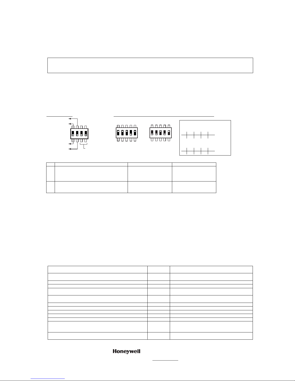
a. Set the DIP switches.
There are two DIP switches on the base unit. The 4-position switch sets the module’s mode; the 5-position switch sets the module’s device address.
Mode DIP Switch: Device Address DIP Switch (identifies the module to the control panel):
AVS-006-V0
DIP SWITCH
NORMAL MODE
PROGRAM MODE
CALLBACK MODE
PANEL TRIGGER MODE
2 3 41
ON
NOT
USED
AVS-007-V0
DIP SETTING FOR
DEVICE ADDRESS 8
(VISTA-15P SERIES)
2 3 541
ON
AVS-008-V1
DIP SETTING FOR
DEVICE ADDRESS 11
(VISTA-20P/
VISTA-21iP SERIES)
2 3 541
ON
ADDRESSABLE MODE SETTINGS:
VISTA-15P Series
DIP Setting for Device Address 8
1 2 3 4 5
ON ON ON off ON
VISTA-20P/VISTA-21iP Series
DIP Setting for Device Address 11
1 2 3 4 5
off off ON off ON
Mode DIP Switch Settings:
SW FUNCTION
ON
OFF
1
Callback mode / Panel Trigger mode Callback mode: Central
Station calls panel to initiate
voice session. Applies to
phone line connection only.
Panel Trigger: Voice session
starts automatically following
delivery of alarm report.
2
Program mode (for callback code) / Normal mode Program Mode: Set switch to
ON to program the callback
code.
Normal mode: Set switch to
OFF when programming of
callback code is complete.
b. Program the Callback Code (applies to phone line only).
Program the 6-digit central station callback code as follows:
1. Set DIP switch 2 to the ON position to enable Callback code programming mode. The system generates a beep every 10 seconds at rem ote
stations to indicate this mode is enabled.
2. Have the central station operator call the premises. The system will go off-hook after it detects a single telephone ring. It will issue a continuous
command-prompt beep to the operator and the LED will flash rapidly indicating that it is waiting for a 6-digit access code to be entered. If no code
digits are entered within 10 seconds, the system will hang up.
3. Have the central station operator enter the 6-digit access code. After the system has detected the access code, it will issue a single beep to the
operator indicating that it is ready for the central station operator to re-enter the code for confirmation.
4. Have the central station operator re-enter the code. If the two entered codes match, the system will issue two beeps and then hang up. If both
codes do not match, or if an invalid key is pressed, the system will issue an error tone (high-frequency beep followed by a low-frequency beep). In
these cases, the system will clear all previously entered digits and wait for a new code to be entered.
5. After the code has been properly programmed, reset DIP switch 2 to the OFF position to disable callback code programming mode. The system will
stop generating beeps at inside remote stations.
IMPORTANT: Avoid programming an access code that ends with the digits "1" or "2". This will prevent the system from unexpectedly entering Talk
or 2-way conversation modes if the last digit of the access code is accidentally pressed twice while entering the code to start a 2-way voice session.
6. 2-WAY VOICE OPERATION – TELEPHONE COMMANDS
Operation
Telephone
Keys
Action
Initiate voice session in low-volume Listen mode. 6-Digit
Access Code
Call premises and enter code.
Select Talk mode. 1 Press momentarily.
Select 2-way voice mode. 2 Press momentarily.
Select Listen mode. 3 Press momentarily. Repeat to toggle between low, mid
and high volume.
Select next inside station and disables all other stations. 4 Press momentarily. Repeat to select next inside station in
sequence again.
Re-initialize 5-minute timeout. 7 Press momentarily.
Return to low-volume Listen mode with all stations enabled. 0 Press momentarily.
Clear key buffer. # Press momentarily.
End voice session. 99 Enter both digits.
Select station number “n” where “n” is 1-3; disables all other stations. ✶ 8n Enter all three digits.
End 2-way voice session, but open 5-minute callback window
(applicable for phone line connection only; not applicable for GSMV
connection to panel).
88 Enter both digits.
Start voice session in low-volume Listen mode (immediate mode
only. Entry of valid access code starts the session in callback mode.)
✶
Press ✶.
2 Corporate Center Drive, Suite 100
P.O. Box 9040, Melville, NY 11747
Copyright © 2008 Honeywell International Inc.
www.honeywell.com/security
 Loading...