

Page 1
Manual Switches AML71/75 Series
Barriers/Panel Seal Accessories
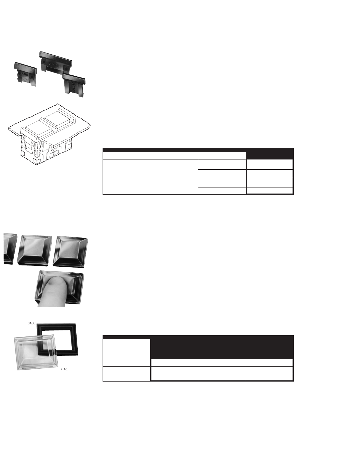
AML71 BARRIERS
Drawing shows two switches, slot mounted. From left to right: one center barrier, a
second switch, plus another end barrier
to complete the arrangement.
When mounting anindividual unit, an end
barrier is attached to each side of the
housing. The center barrier is used in a
slot mount array.
FEATURES
1 Barriers separate individually
mounted switches and indicators —
help prevent inadvertent actuation of
two pushbutton switches with a single
push.
1 Front of panel mounting simplifies
installation.
AML71 BARRIER ORDER GUIDE (See notes)
Barriers shown in order guide are black.
Barrier Length Type Catalog Listing
Short Center AML71SCB
(For use with square devices and short side
of rectangular devices.) End AML71SEB
Long Center AML71LCB
(For use with long side of rectangular
devices.) End AML71LEB
Notes:
Not for use with AML61 mounting hardware or any full guard bezel products.
Not for use with AML41J, K, or L lens type indicators; or AML45 annunciators.
AML75 PANEL SEAL
MATERIAL
Base: Polypropylene
Cap: Polyvinyl Chloride
FEATURES
1 AML75 panel seals fit pushbutton
switches and indicators.
1 Provides protection from
contamination from accidental
beverage spills, dust, and dirt.
1 Easy to install, without tools
1 No effect on display color, light
intensity, or legend quality.
1 Replace seal or change lamps without
removing switch from panel.
1 For .19-inch standard height square or
rectangular pushbuttons.
1 Mounting dimensions page 65.
AML75 PANEL SEAL ORDER GUIDE
Square .19N Rectangular .19N
Description high pushbuttons high pushbuttons Rockers
Base & Seal AML75ABC AML75BBC AML75RBC
Base Only AML75ABN AML75BBN —
Seal Only AML75ANC AML75BNC —
Notes:
Multiple units should not be mounted in a
single slot, since this would create an
unsealed space between each unit.
AML75 seals are not for use with barriers,
The design complements AML’s functional appearance, creating a pleasing
framed effect around the button. It consists of a matte black plastic base which
press-fits between the panel and switch
bezel, and a transparent flexible seal
which snaps into the base. PK 8521, shipped with each order, provides installation
instructions.
Button colors and legends can be viewed
without distortion whether lighted or unlighted. Seals can be conveniently replaced or removed for relamping, without
removing the switch from panel.
Operating temperature range is 32° to
131°F(0°to 55°C).
For Use With:
full guard bezels, AML61 mounting hardware, AML45 annunciators, or AML41J,K,
or L lens type indicators.
56Honeywell1SensingandControl11-800-537-6945USA1F1-815-235-6847International11-800-737-3360Canada
Page 2
Manual Switches AML76/78 Series
Switch Guard/Panel Plugs, Dummy Housings
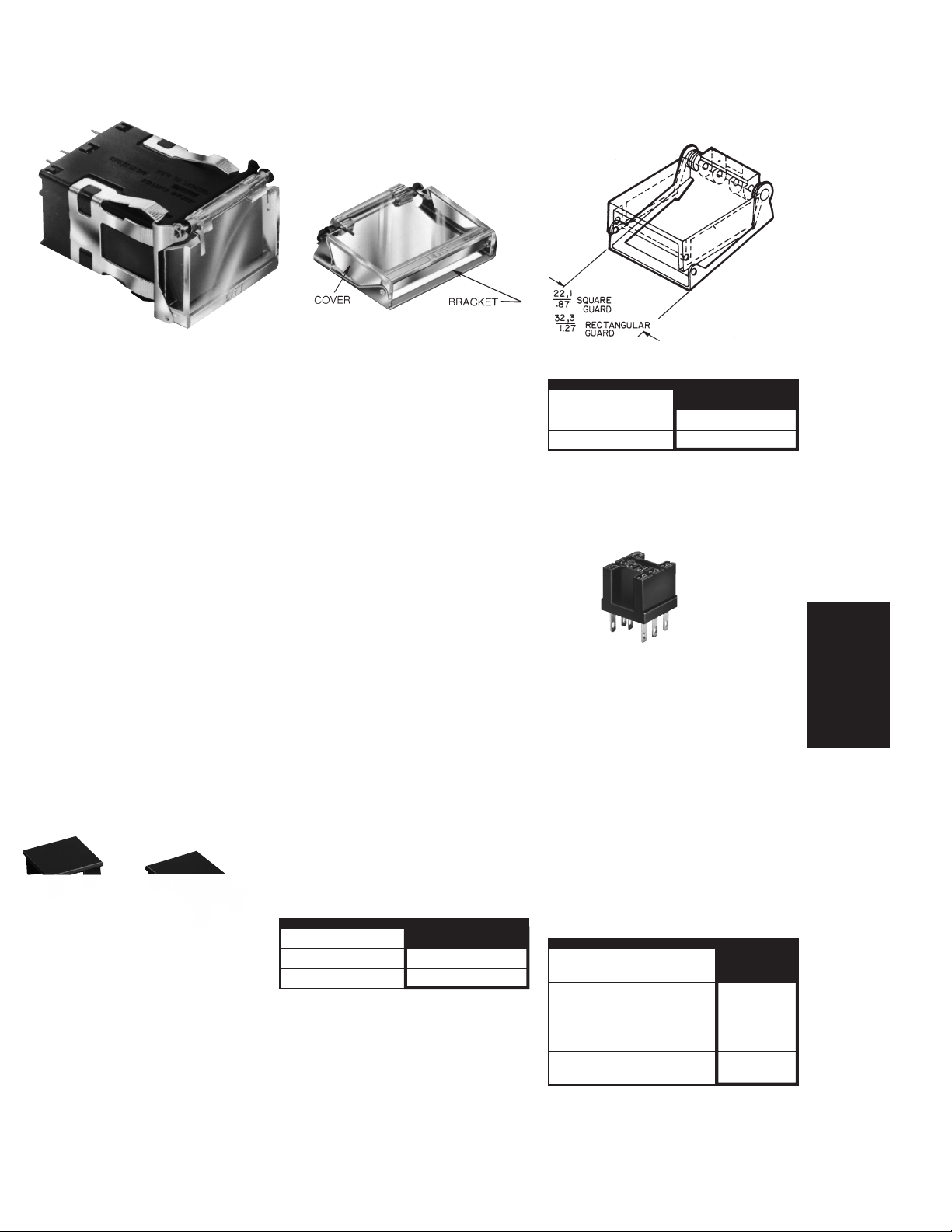
FEATURES
1 Button cannot be operated when
switch guard cover is closed,
preventing accidental operation
1 Wire lock-down feature further
prevents unintentional actuation of the
switch.
1 Lamps can be replaced with the
switch guard attached, without
special tools, saving maintenance
time
1 Can be used with alternate or
momentary action square or
rectangular .19 inch standard height
AML buttons
1 Shock resistant construction, for long,
maintenance-free life
AML76 switch guard protects square
and rectangular .19-inch standard
height pushbuttons from inadvertent
actuation. It is for use with standard
bezel type switches only.
See page 65 for mounting dimensions.
AML78 PANEL PLUGS
Plastic panel plugs (shown above) enable the user to provide for future needs
by punching extra panel holes. Finished
in matte black, they are the same height
as the standard AML bezel when snapped in place from the panel front.
The switch guard cover is clear, polycarbonate thermoplastic through which the
button is easily visible. The word ‘‘lift’’ is
molded onto the top front edge of the
guard. The bracket is bright-finished
stainless steel.
The switch guard may be assembled to
the AML pushbutton before the switch is
installed in a panel. Or, the guard can be
assembled to a pushbutton already
mounted in a panel, providing the wiring
is sufficiently slack to raise the switch bezel above the panel; and if there is sufficient clearance with adjacent units. PK
8522 contains installation instructions
and is shipped with each order.
AML switch guards may be mounted in
horizontal or vertical matrices. A wire
lock-down feature, using .020-inch diameter locking wire, may be usedasanadditional protection.
Panel plugs are only for use in individual
holes or with AML61 mounting hardware
in multi-station strips. (Use dummy housings in strip cutouts without AML61
mounting hardware.)
PANEL PLUG ORDER GUIDE
Plug Type Catalog Listing
Square AML78CB
Rectangular AML78FB
SWITCH GUARD ORDER GUIDE
Guard Type* Catalog Listing
Square AML76C10T01P
Rectangular AML76F10T01P
* The word‘‘LIFT’’ is molded into the cover. If other
languages are desired contact the 800 number.
Note: Switch guard is not designed for use with
AML61 mounting hardware, AML71 barriers, or full
guard bezel switches.
CONNECTOR BLOCK
AML79CC
This connector block can be used with
square 1 and 2 pole AML21 and AML22
switches with .110 × .020 terminals to
enable plug-in wiring.
AML78 DUMMY HOUSINGS
Dummy housings can be used to provide
for expansion needs in strip cutouts without AML61 mounting hardware. They
have mounting clips, butthereis no provision for switching or illumination.
DUMMY HOUSING ORDER GUIDE
Dummy Housing Type* Listing
Square AML78C100
(Pushbutton style)
Rectangular AML78F100
(Pushbutton style)
Rectangular AML78J100
(Lens indicator style)
* Order AML51 Buttons/lenses for use with dummy
housings.
Catalog
Manuals
Honeywell1SensingandControl11-800-537-6945USA1F1-815-235-6847International11-800-737-3360Canada57
 Loading...