

Page 1

Manual Switches AML Series
Advanced Manual Line
IN FRONT OF THE PANEL
Coordinated, attractive appearance.
AML features innovations designed byindustrial designers to achieve the best balance of human factors and aesthetic appearance. Operator height, bezel size,
and the compatibility of square and rectangular shapes blend with other components to harmonize your panel. There’s
no visual clutter to distract from man/
machine communication.
This comprehensive line of lighted and
unlighted manual controls features:
1 Pushbuttons for high and
intermediate frequency functions;
1 Rocker and paddle switches, with 2 or
3 positions, for less frequent control
functions;
1 Plus lighted indicators and
annunciators which complement
AML’s universal appeal.
Various controls can be matched with
their functions to accommodate the most
natural and efficient habit pattern reflex.
Keylock operated switches can be used
to assure ‘‘authorized personnel only’’
access.
Display flexibility. AML offers a choice of
five legend sizes, four button heights, full
or split section display, and illumination
by incandescent lamps, LED’s or neons.
Colors are brightanduniform, providing a
strong definition andgood visibility. (Nonilluminated devices have the sameattractive colors.)
BEHIND THE PANEL
AML’s simple, cost effective design provides many behind-panel benefits for the
designer and installer/user.
Simple to install. They snap in from the
panel front individually or in vertical or
horizontal strips; or in subpanel mounted
strips and matrices that can be pre-assembled and pre-wired to assure accurate alignment and efficient panel building.
Electrical flexibility. Solid state switches
with Hall effect integrated circuits
interface directly with microprocessors
and other logic level devices. These IC’s
were first applied inMICRO SWITCH solid
state keyboards. Today, many MICRO
SWITCH products incorporate the Hall
effect technology to meet a wide range of
position sensing and manual control
needs.
Electronic control switches with gold or
silver contacts, and 1, 2, or 4 poles, will
handle up to 3 amps. Including an encoded version which generates different binary coded outputs merely by changing
cam-keyed buttons.
Power duty switches meet line disconnect application needswith 10-amp pushbuttons and 15-amp paddle and rocker
switches.
Easy to wire. All AML devices present
single level termination. This means faster, easier, neater, and more economical
wiring. And there is a choice of solder,
quick-connect, push-on, and printed circuit termination.
MATING RECEPTACLES
The .110 × .020 quick-connect/solder terminal (types 2 and 8) is designed for use
with receptacles that comply with the UL
standard for insertion and withdrawal
forces. Maximum insertion force is 12 lbs.
max., withdrawal force is 14 lbs. These
receptacles are supplied by: AMP Inc.,
Berg, Augat, Hollingsworth, MALCO,
Zierick, and others. Refer to Thomas Register or the Yellow Pages for the location
of your local supplier.
Manuals
Color display options include:
1 Transmitted color — color can be
distinguished whether lamp is On or
Off.
1 Dead front — display appears black,
until illumination causes legend and
color to appear.
1 Projected color — white display is
diffused with color when illuminated.
Honeywell1SensingandControl11-800-537-6945USA1F1-815-235-6847International11-800-737-3360Canada17
Page 2
Manual Switches AML Series
Advanced Manual Line
FEATURES
1 Complete selection of pushbutton,
rocker and paddle (toggle type)
switches accommodates different
functions and promotes operator
efficiency.
1 Solid state, electronic, and power
duty control.
1 Full or split screen incandescent
display switches and indicators
provide vivid transmitted color,
projected color (for neutral display
when unlit), and dead front (hidden
color).
1 Wide-angle visibility LED and line
voltage neon display switches and
indicators.
1 Annunciators back-lighted by LED’s
enable high density message display.
1 Keylock switches available for
controlled access applications.
1 All AML terminations at the same
shallow depth (1.7 in. /43,1 mm) for
convenient wiring or PC board
termination.
1 Snap-in surface mount or sub-panel
(hidden bezel) mount with mounting
hardware.
1 Pad printed legends with a clear
polyurethane overcoat available in a
choice of five standard sizes.
1 Metric design for worldwide accept-
ance.
1 UL recognized, CSA certification.
1 Selected listings are certified by VDE
and CE. (For compliance status,
contact the 800 number.)
MICRO SWITCH AML Advanced Manual
Line combines functional flexibility with
electrical versatility to provide a broad
range of options to choose from.
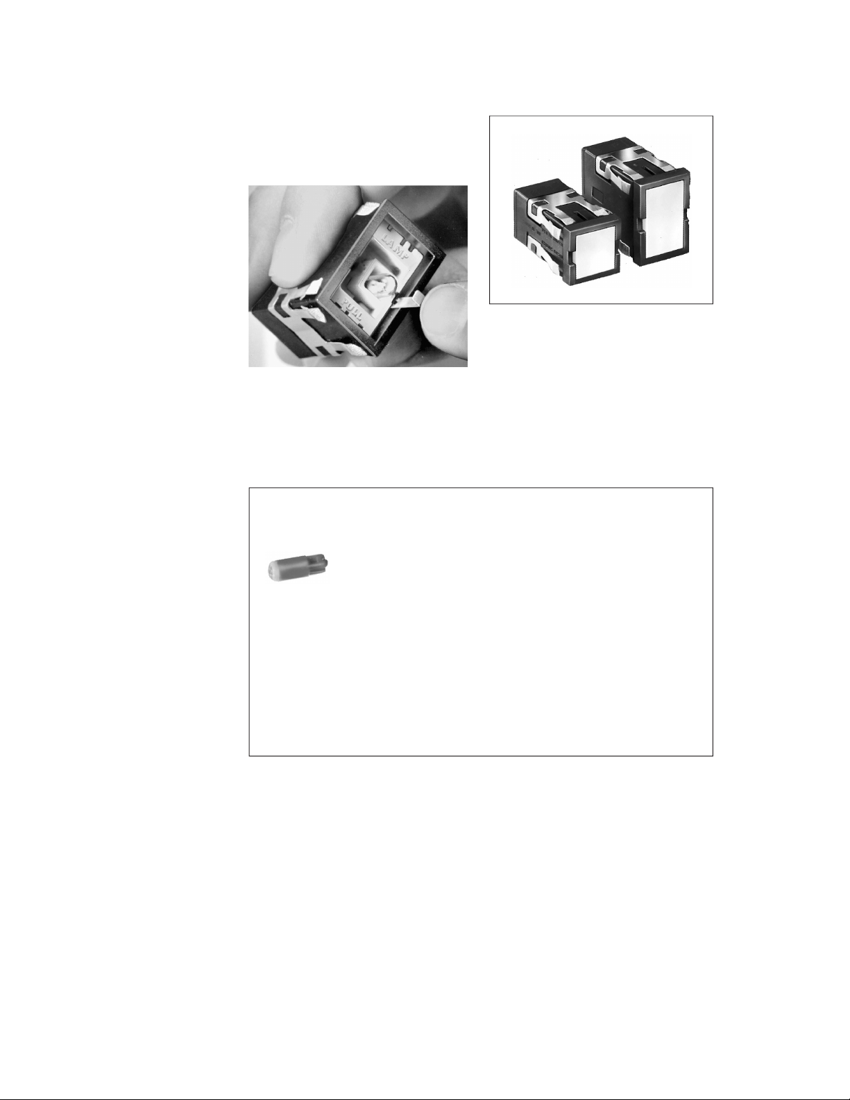
EASY TO RELAMP
Relamping of T-1-3/4 incandescent
AML91 lamps is accomplished from the
front of the panel without tools. (AML92
T-1-3/4 LEDs can be added in the same
manner.)
High Intensity LEDs For Full-face AML Lighted Display
AML92 Series
1 Full-face illumination for high visibility lighted colors.
1 Advanced illumination technology combines high-intensity LED in standard
T-1-3/4 wedge base lamp package.
1 Easy plug-in installation in AML lighted switches and indicators.
1 Low operating temperature permits high density, continuous operation with
minimal heat build-up.
FULL GUARD BEZEL OPTION
As an alternative to standard height bezels (.06 in./1,5 mm), pushbutton switches can be furnished with full guard bezels
extending .19 in./5.0 mm from the mounting surface. In the free position, standard
buttons are flush with full guard bezels.
The raised bezel guards against accidental operation by someone leaning against
or dropping something on a control console.
AML92 Series LEDs have a quad chip assembled in a T-1-3/4 wedge base lamp
package. They provide full-face illumination when used with lighted pushbutton,
rocker and paddle switches, or indicators equipped with incandescent lamp
sockets. For ordering information, refer to page 58.
18Honeywell1SensingandControl11-800-537-6945USA1F1-815-235-6847International11-800-737-3360Canada
Page 3

Manual Switches AML Series
Advanced Manual Line
AML CHARACTERISTICS
AML 10 Series AML 20 Series AML 30 Series AML 40 Series
Electrical/Mechnical Life* N/A
Pushbuttons–Momentary 1,000,000 25,000 (silver)/
Pushbuttons–Alternate 25,000 25,000 25,000 --Rockers 25,000 25,000 25,000 --Paddles 25,000 25,000 25,000 ---
Agency Ratings
(May not apply to every
series division)
UL File E53576 File E12252 File E12252 File E58932
CSA File LR4442 File LR4442 File LR4442 File LR4442
VDE None File 0630/10.78+ File 0630/10.78++ None
CE Rating 1710 Rating 1710
*95% Survival
+ Exception: Four-Pole AML’s are not included in VDE Approval
++ Exception: Only the 2-pole AML33 and AML34 are certified by VDE
100,000 (gold)
No. 4275.5788 No. 4275.5788
25,000 ---
AML ELECTRICAL DATA
1
AML10 Series
Electrical Characteristics Absolute Maximum Rating4
Output
Integrated Supply Output Current Rise Fall Supply Externally Loads
Circuit Current Voltage max. 10% to 90% to Voltage Applied to to Storage
Function (Max.) (Operated) (Released) 90% 10% (V
5 VDC 3.5 mA +.4 Volt 2.0 µA 1.0µsec 1.0µsec –.5 to +7.0 –.5 Volt min. 20 mA –40°Cto
Sinking1 (Released) (Sinking (Sinking (Sinking VDC +15 Volts max. (Sinking) +65°C
6-16 VDC 6.5 mA @ + .4 Volt 20 µA 1.5µsec 0.5µsec –1.2 to +20 +20 VDC max. in 40 mA –40°Cto
Sinking2 6 VDC. (Sinking (Sinking (Sinking VDC Off condition only +65°C
4.5-24 VDC
Sinking
1 Over temperature range of 0°to +55°C(+32°to 2 Over temperature range of 0°to +55°C(+32°to 4 As with all solid state components, performance can be
+131°F) and supply voltage of 4.5 to 5.5 VDC. +131°F) and supply voltage of 16 VDC. expected to deteriorate as rating limits are approached;
6.5mA 8 mA) 8 mA) 8 mA) 0° to +65°C (Off condition) (–40° to
(Operated — (+32° to +149°F)
no load) +149°F)
10.0 mA @ 20mA 20 mA) 20 mA) –0.5 VDC min. in (–40° to
16 VDC max.) Off or On +149°F)
(Plus load condition.
current)3
5V
7.0 mA
(Released)
24 V
9.0 mA
(Released)
14.0 mA
(Operated-
no load)
+.4 Volt
(Sinking
10 mA)
Leakage Voltage
10 µA 1.5 µsec
3 At 24°C. (+75°F)
Switching Time
Max.
(Sinking
10 mA)
0.5 µ sec
(Sinking
10 mA)
) Output Output Temperature
S
–30 to +30
VDC
–0.5 Volt min. +24
Volts max. (Off
condition)
however, they will not be damaged unless the limits are
exceeded.
20 mA
(Sinking)
–40−Cto
+65°C (–40°
to +149°F)
1 AML20 Series
Contacts Voltage Current Load Type
Silver 250 VAC 2 Amps 75% Power Factor
or 125 VAC 3 Amps 75% Power Factor
Gold-plated Silver 24 VDC 2 Amps Resistive
Gold 125 VAC/DC 100 mA Resistive
Manuals
1 AML30 Series
Current
Voltage Pushbuttons Rockers or Paddles Load Type
125 VAC 10 amps 15 amps 60% power factor
250 VAC 10 amps 15 amps 60% power factor
Honeywell1SensingandControl11-800-537-6945USA1F1-815-235-6847International11-800-737-3360Canada19
Page 4
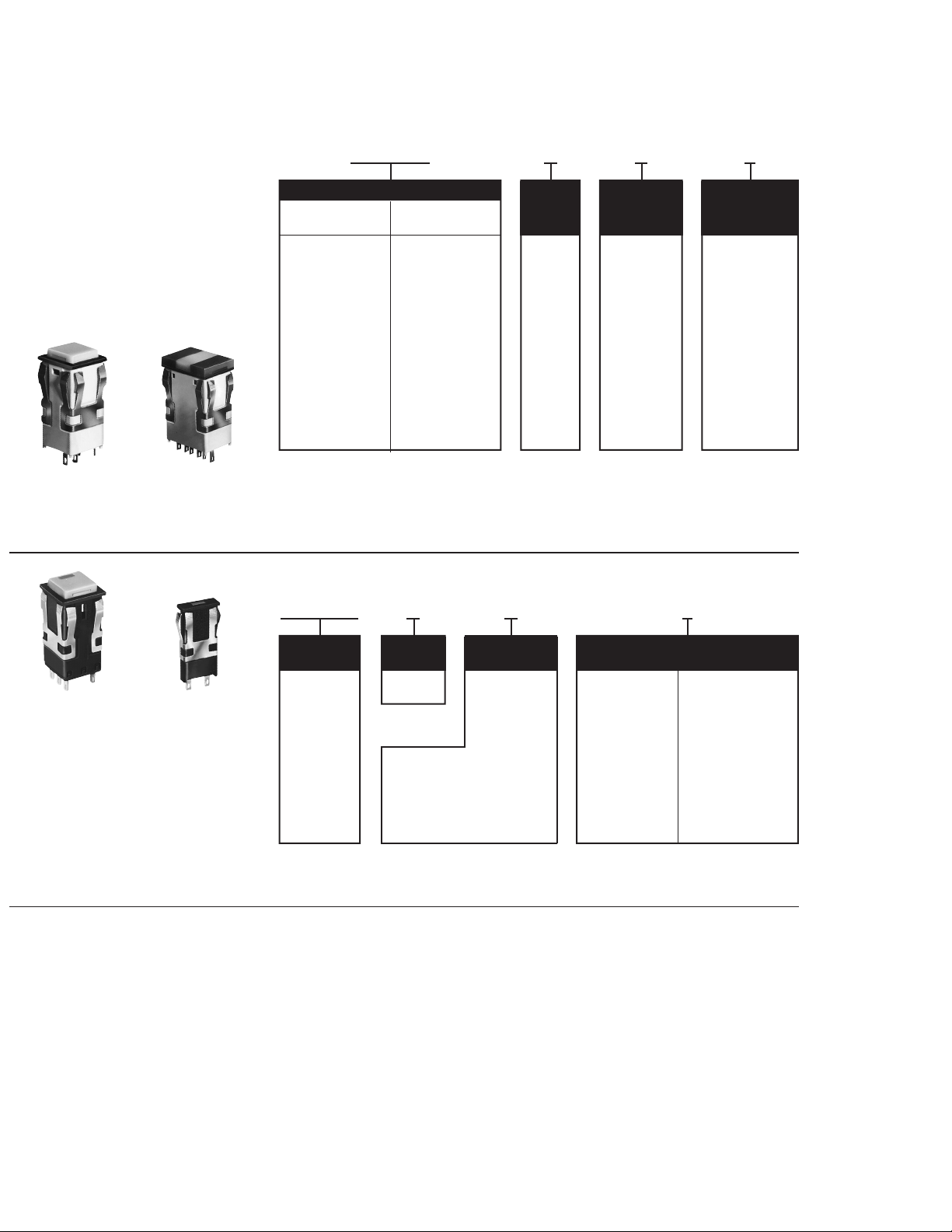
Manual Switches AML41/42 Series
Lighted Indicators
To order lamps see page 58.
FEATURES
1 Pushbutton style indicators match
display of standard bezel lighted
switches. Choice of incandescent
or LED illumination.
1 Lens style indicators use a special
cap-like button which covers the
bezel to present a larger display area,
without affecting family appearance.
Up to 3-lamp split screen capability.
Incandescent illumination.
AML41 AML41
(Use AML51 push- (Use AML51-J/-K/-L
buttons only. lens buttons only.
Page 42.) Page 42.)
AML41 INCANDESCENT DISPLAY INDICATORS ORDER GUIDE
AML41 C B A 2
Housing Type
Pushbutton Lens Bezel Lamp Terminal
Style: Style: Color Type Type
AML41 C AML41 J B A 2
Square
1 lamp ckt.
AML41 D
Square
2 lamp ckts.
AML41 F
Rectangular
1 lamp ckt.
AML41 G
Rectangular
2 lamp ckts.
Rectangular
1 lamp ckt.
AML41 K
Rectangular
2 lamp ckts.
AML41 L
Rectangular
3 lamp ckts.
* Lamps will be installed per each lamp circuit specified in the Housing Type.
Black No lamp
Examples:
AML41CBA2
Square (pushbutton style) indicator
housing with one lamp circuit; black bezel; .110 × .020 termination.
AML41JBA2
Rectangular (lens style) indicator housing with onelamp circuit; black bezel; .110
× .020 termination.
AML42 LED DISPLAY INDICATORS ORDER GUIDE
LEDs are not replaceable.
Incand.
installed
B
6 V Lamp*
C
14 V Lamp*
E
28 V Lamp*
.110 × .020
(Solder or Quick-
Connect)
.025 × .025
or Push-On)
AML42 S B C 2
3
(Printed
Circuit
AML42C AML42S
(Use AML52-C/-A
pushbuttons only.
Page 43.)
Housing Bezel LED Color/ Terminal Type/
Type Color Voltage Diode Protection
AML42 C B Red 2 8
Square Black B V* .110 × .020 .110 × .020
1 LED C 5 V (Solder or Q.C.) w/diode to
AML42 S E 15 V 3
Compact F 24 V .025 × .025 9
1 LED Yellow Green (Printed Circuit .025 × .025
H V* R V* or Push-On) w/diode to
J 5V S 5 V protect LED
K 10 V T 10 V
L 15 V W 15 V
M 24 V X 24 V
Example: AML42SBC2
Compact indicator with black bezel; 5volt
D 10 V protect LED
* See LED application data, page 58, for these
devices without current-limiting resistor.
red LED; .110 × .020 termination.
36Honeywell1SensingandControl11-800-537-6945USA1F1-815-235-6847International11-800-737-3360Canada
Page 5

Interactive Catalog Supplements Catalog PDFs
If you need detailed product information, or help choosing the right
product for your application, see our Interactive Catalog. Use the
Interactive Catalog to access the most complete and up-to-date
information available.
Sensing and Control
Interactive
Catalog...
The Interactive Catalog provides an extensive collection of product
specifications, application data, and technical literature that can be
searched based on criteria you select.
This PDF catalog information was published in November 2000.
Sensing and Control
Honeywell Inc.
11 West Spring Street
Freeport, IL 61032
Click this icon to try
the Interactive Catalog.
www.honeywell.com/sensing
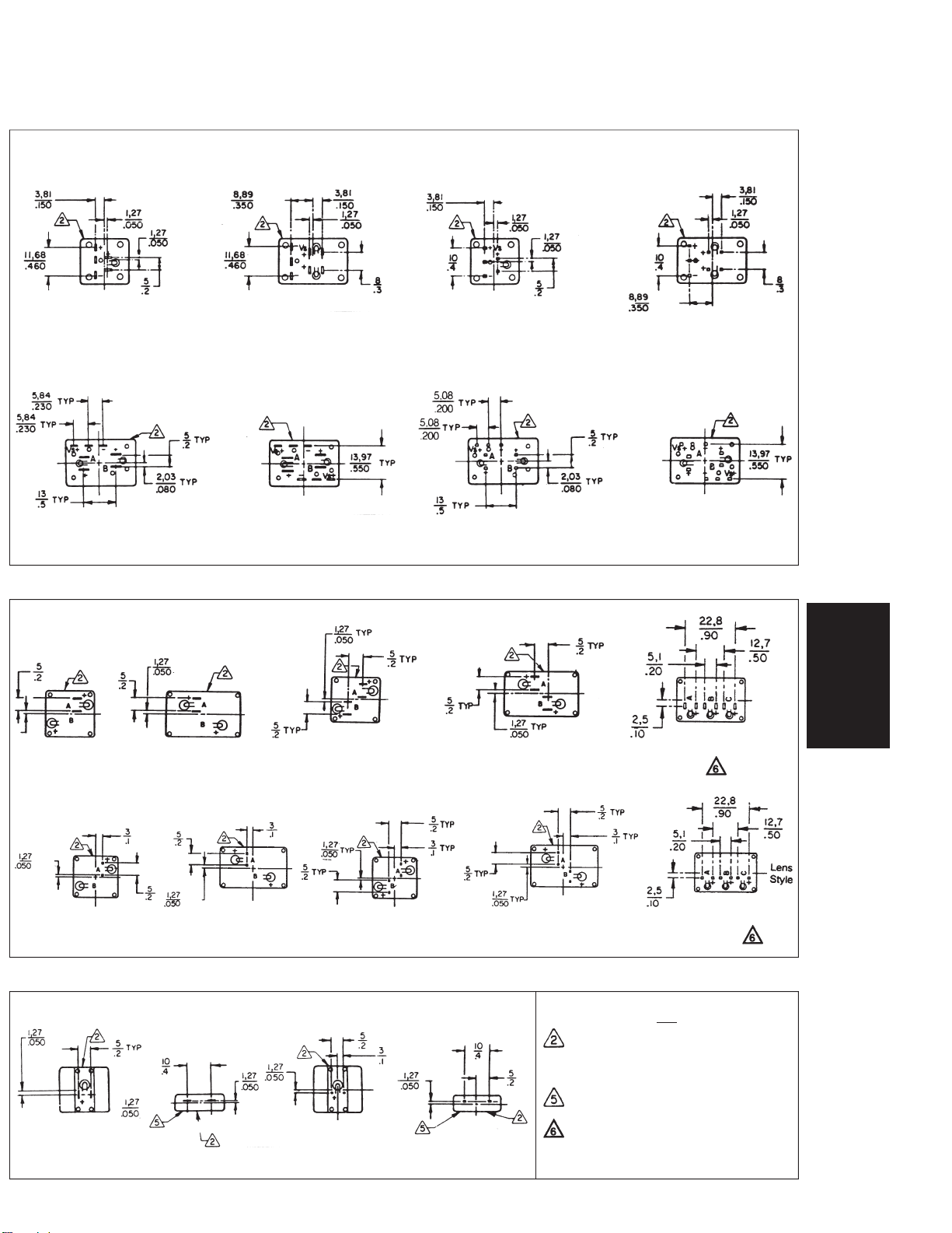
Page 6
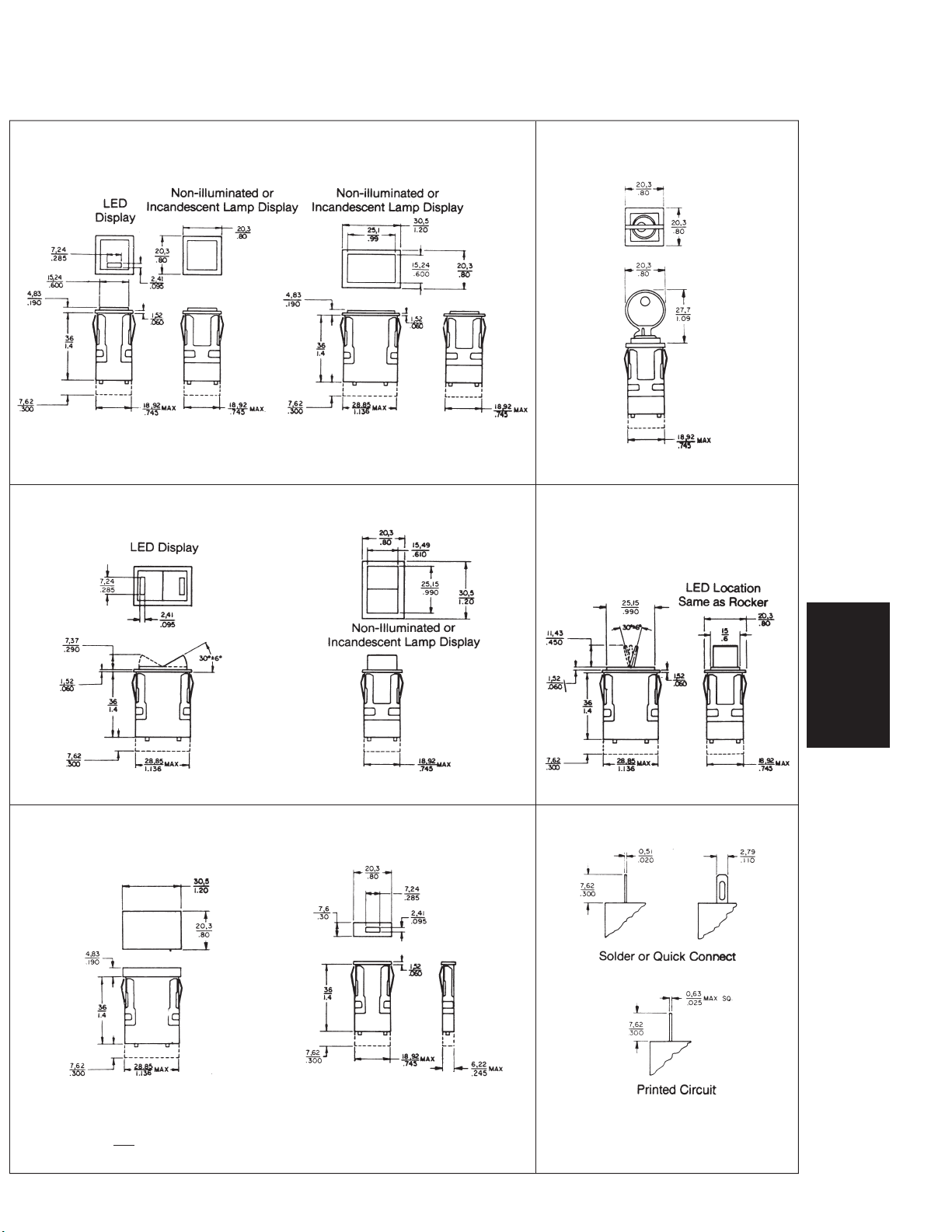
Manual Switches AML Series
Mounting Dimensions (For Reference Only)
AML11/12 and 21/22 SWITCHES Note: Topof full guard bezel housing AML27 SWITCHES
AML41C/D and AML42C INDICATORS .19/5,0 from panel.
PUSHBUTTONS
KEYLOCK
Forterminallocations,seepage49.
Forterminallocations,seepage50.
AML14/16 and AML24/26 SWITCHES AML13/15 and 23/25 SWITCHES
ROCKERS PADDLES
Forterminallocations,seepage49/50.Forterminallocations,seepage49/50.
AML41 INDICATOR AML42 INDICATOR TERMINAL TYPES
LENS STYLE MINIATURE
Manuals
Forterminallocations,seepage50.
NOTE
1Dimensions are
Honeywell1MICROSWITCHSensingandControl11-800-537-6945USA1F1-815-235-6847International11-800-737-3360Canada47
mm or mm/IN
IN
Solder Hole will accept two #22 AWG
Stranded Conductor (per NEMA publication
DC-2 1976)
Page 7
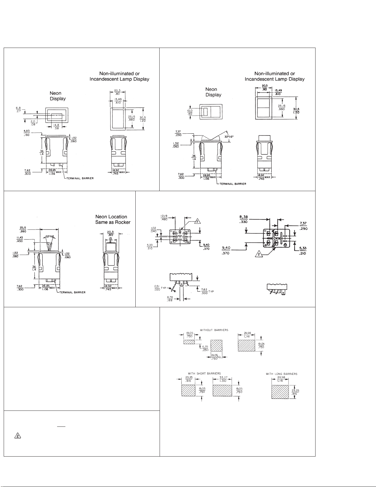
Manual Switches AML Series
Mounting Dimensions (For Reference Only)
AML31/32 SWITCHES AML34/36 SWITCHES
PUSHBUTTON ROCKER
AML33/35 SWITCHES TERMINAL LOCATIONS
PADDLE PUSHBUTTON ROCKER AND PADDLE
PANEL CUTOUT FOR SINGLE-STATION
FRONT-OF-PANEL MOUNTING
Recommended panel thickness: .060-.187/1,52-4,75
NOTES
1 Dimensions are
Manufacturers logo onthis side of housing
Solder Hole WillAccept One #14AWG Stranded Conductor
(Per NEMA PublicationDC-21976)
48Honeywell1MICROSWITCHSensingandControl11-800-537-6945USA1F1-815-235-6847International11-800-737-3360Canada
mm or mm/IN
IN
PANEL PUNCH FOR AML SERIES
A panel punchis manufactured by Greenlee-Textron Tool Co.,
Rockford, IL (815-926-3011).
Page 8
Manual Switches AML Series
Mounting Dimensions (For Reference Only)
TERMINAL LOCATIONS FOR AML10 SWITCHES
PUSHBUTTONS
Solder and Quick-Connect Printed Circuit
Illuminated devices shown(non-illuminated devices do not have lamp terminals).
ROCKERS AND PADDLES
Solder and Quick-Connect Printed Circuit
One Integrated Circuit Two Integrated Circuits One Integrated Circuit Two Integrated Circuits
Illuminated devices shown(non-illuminated devices do not have lamp terminals)
TERMINAL LOCATIONS FOR AML41 INDICATORS
Solder and Quick-Connect
1 Incandescent
Lamp Circuit
Printed Circuit
1Incandescent 1 Incandescent 2Incandescent 2 Incandescent 1-3Incandescent
Lamp Circuit Lamp Circuit Lamp circuits Lamp Circuits Lamp Circuits
1 Incandescent
Lamp Circuit
2 Incandescent
Lamp Circuits
2 Incandescent
Lamp Circuits
1-3 Incandescent
Lamp Circuits
Manuals
TERMINAL LOCATIONS FOR AML42 INDICATORS
Solder and Quick-Connect Printed Circuit
1 LED Circuit 1 LED Circuit 1 LED Circuit
Honeywell1MICROSWITCHSensingandControl11-800-537-6945USA1F1-815-235-6847International11-800-737-3360Canada49
1 LED Circuit
NOTE
1 Dimensions are
Manufacturer’s logo onthis side of
housing
4 – Lamp terminals are not provided for
non-illuminated devices
positive terminal ident.(+) marked this
side of housing
1 – lamptermination identified by‘‘B’’.
2 – lamptermination identified by‘‘A’’
and‘‘C’’.
MM or MM/IN
IN
Page 9

Manual Switches AML Series
Mounting Dimensions (For Reference Only)
TERMINAL LOCATIONS FOR AML20 SWITCHES
PUSHBUTTON SWITCHES
Solder or Quick-Connect
1 Pole 4 Pole2 Pole
PUSHBUTTON SWITCHES
Printed Circuit
Terminal identification markedon each adjacent side ofhousing
KEYLOCK SWITCHES
Solder or Quick-Connect
Printed Circuit
1Pole
1Pole 2 Pole
ILLUMINATED ROCKERS AND PADDLES
Solder or Quick-Connect
1Pole 2Pole 1Pole 2 Pole
NON-ILLUMINATED ROCKERS AND PADDLES
Solder or Quick-Connect Printed Circuit
2 Pole
Printed Circuit
4 Pole
1Pole 2 Pole 4 Pole
50Honeywell1MICROSWITCHSensingandControl11-800-537-6945USA1F1-815-235-6847International11-800-737-3360Canada
Page 10

Manual Switches AML Series
Mounting Dimensions (For Reference Only)
ANNUNCIATORS
AML45 SERIES
Manufacturer’s logo onthis side of housing
Forpanelpunchmanufacturer,seepage48.
Manuals
Honeywell1MICROSWITCHSensingandControl11-800-537-6945USA1F1-815-235-6847International11-800-737-3360Canada51
Page 11
Manual Switches AML Series
Mounting Dimensions (For Reference Only)
MULTI-STATION FRONT-PANEL MOUNTING
Panelcutouts
Square Switches & Indicators Rect. Switches & Indicators Annunciator
(.8) (No. ofunits) — .045* (1.20) (No. ofunits) — .045* (.40) (No. of units) —.045*
(20,3) (No. ofunits) — 1,14* (30,5) (No.of units) — 1,14* (10,1) (No. ofunits) — 1,14*
For each barrier,add .053/1,35 * Note: If barriers are used, do not subtract.045 in./1,14mm fromthe panelcutout
(Seepage48 forpanelpunchmanufacturer.)
formula. (.045 in./1,14mm is the allowance forthe widthof the bezel.)
AML61MULTI-STATION SUBPANEL MOUNTING
Panel cutouts for AML61
Mounting Bracket
Orientation Width Length
A* in. .810
B in. .810
C or D* in. 1.210
*Morethan twocans withmountingbrackets requiredfor strips
of more than 10units.
mm 20,57 (.810)(No. ofunits)
mm 20,57 (1.210)(No. ofunits)
mm 27,94 (.810)(No. ofunits)
AML61MOUNTING CENTERS
Mounting Bracket
Orientation 123456789101112
‘‘
A’’ or‘‘C’’ in. 1.285 2.095 2.905 3.715 4.525 5.335 6.145 6.955 7.765 8.575 9.385 10.195
‘‘
B’’ in. 1.685 2.895 4.105 5.315 6.525 7.735 8.945 10.155
‘‘
D’’ or‘‘E’’ in. on C
mm 32,64 53,21 73,79 94,36 114,94 135,51 156,08 176,66 197,23 217,81 238,38 258,95
mm 42,80 73,53 104,27 135,00 165,74 196,48 227,20 257,94
.807 1.614 2.421 3.228 4.035 4.842 5.649 6.456 7.263 8.070 8.877
L
mm on C
20,50 41,00 61,49 81,99 102,49 122,99 143,48 163,98 184,48 204,98 225,48
L
Mounting Centers/Number of Cans
Tolerance J ±.015
D
C
E
B
A
52Honeywell1MICROSWITCHSensingandControl11-800-537-6945USA1F1-815-235-6847International11-800-737-3360Canada
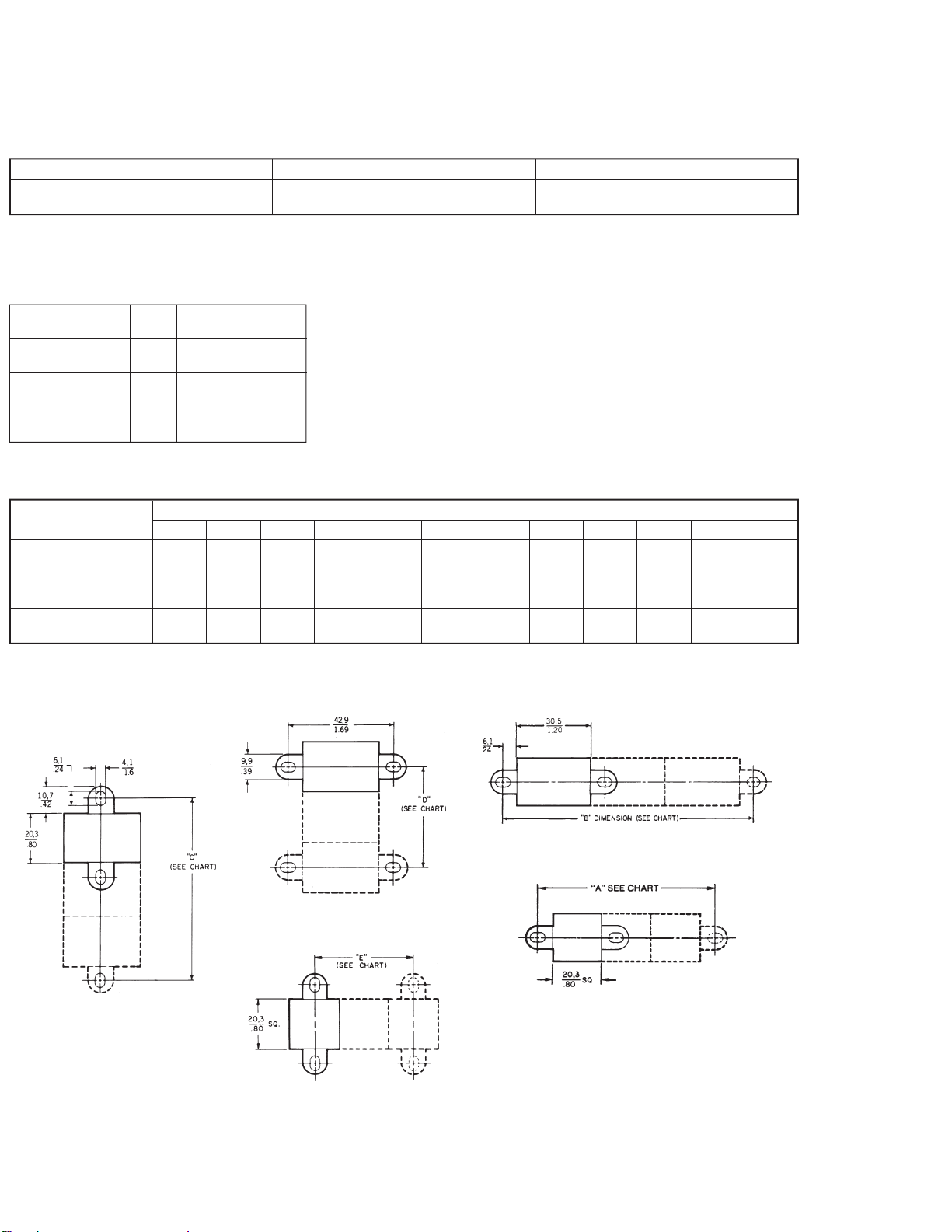
Page 12

Manual Switches AML Series
Mounting Dimensions (For Reference Only)
AML75 PANEL SEAL ACCESSORY
Panel cutouts
Multiple panel sealedunits should notbe
mounted together in a single elongated
slot, since this would create an unsealed
space between each unit.
Side-by-side mounting can be achieved,
per the center-to-center dimensions
shown in the drawing. (Dotted lines indicate the seal bases which are abutting
at front of panel.)
AML75 seals are not designed for use
with the AML61mounting system.
NOTE:Suggestedcutoutdimensionsare
based on an .125N/3,18 mm panel thickness.Individualpreferences forinpanelfit
may require measurement of assemblies
before panels are cut.
AML76 SWITCH GUARD ACCESSORY
Manuals
PANEL CUTOUTS
Honeywell1MICROSWITCHSensingandControl11-800-537-6945USA1F1-815-235-6847International11-800-737-3360Canada53
 Loading...