

Page 1
- - - -
--
--
Honeywell
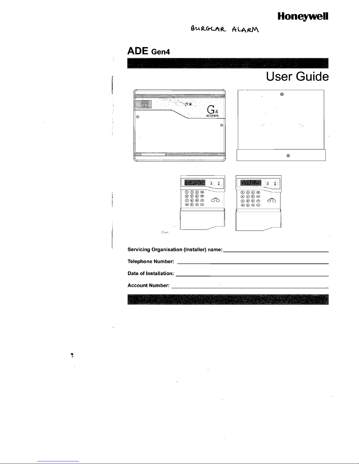
ADE Gen4
- -
------.----
-
User Guide
G4
ACCENTA
@
@
I
CD
00
0
0006
0®®0
0@@0
-----
6-6
T---,CD~0"0~0=-'
-------------------
0006
0®®0
6-6
0@@0
Servicing Organisation (Installer) name:
______________
_
Telephone Number:
_____________________
_
Date of Installation:
_____________________
_
AccountNumber:
______________________
~
~-----~
-~---
- -
----~
------;;--
--------~~-~-----:-~~-~~~.--~-~~--~-.::::------~--~-~
-
_____
::.--"'-
___________
~
-
_______
~
_ _ -~ -
-.~
~
_:;".0 ~ _
~~
- - • <
I
Page 2
Table ofContents
User
Guide
·Contents
Introduction
........................•............................................................ 1
Codes ............................................................................................... 1
Alarm System Operation ................................................................ 1
Pe
rson al Atta
ck
............................................................................... 1
Fire Zones ........................................................................................ 1
Power Indicator ............................................................................... 1
Signalling Device ............................................................................ 1
How
to
Set the System ................................................................... 2
How
to
Unset
the
System ............................................................... 3
How
to
Part Set
the
System ........................................................... 4
How
to
Silence an
Alarm
and Reset the System .......................... 5
How
to
Omit
Zones ......................................................................... 6
How
to
Quick
Set the System ........................................................ 7
Single Key Setting .......................................................................... 7
How
to
Set Up Chime Mode ........................................................... 8
Changing Codes
using
User 1 ....................................................... 9
Changing Codes
using
User 2 ..................................................... 10
How
to
Delete User Code 2 .; ........................................................
11
To delete
user
code 2 using
user
code
1.................................................
11
To delete
user
code 2 using
user
code
2................................................. 12
Duress Code .................................................................................. 13
How
to
View the Event Log .......................................................... 14
How
to
Test
Your
Alarm
system
.................................................. 15
How
to
Test
the
Bell, Strobe and Internal
Sounder
................................ 15
How
to
do
a Walk Test ................................................................ 17
How
to
Set
up
the Time and Date ............................................. 18
Page 3
Features
User
Guide
I
J
Introduction
This User Guide tells you how to operate your intruder alann system.
To
simplify this User Guide we
have assumed that the alann system has been installed
by
a professional intruder alann system installer
(the installer), and that the system is operated in a "typical" way. Aspects
of
your system that are not
"typical" will be described
by
your installer.
NOTE:
If
you have any questions about your intruder alann system, then consult your installer, see
contact details at the front
of
this User Guide.
Codes
To operate the alarm system you will need to use a code. A code is 4 digits long, and can
be
any
number from 0000 to 9999. By default user code I is [0][1][2][3] but you should change this as soon
as possible.
Alarm System Operation
This booklet describes three versions
ofthe
alarm system.
You
operate the system
by
pressing keys on
the keypad and viewing the indicators. Both alann systems work the same way.
Personal Attack
If
the installer has programmed personal attack
on
the keypads and
if
you are under threat,
or
are being
attacked, you can activate the alarm by pressing the 4 and 9 keys
at
the same time on any LED keypad.
You can also press the two keys marked PA on the remote
LCD
keypad. The alann system will
produce a loud alarm sound, and the external siren will
be
turned on.
Fire Zones
Zones 7 and 8 on your alarm system may have a Fire
or
Smoke detector connected to it. In the event
of
a fire the alann system will produce a distinctive,two-tone fire alarm sound, and the outside siren will
pulse 2 seconds on, 2 seconds off. You should leave the premises immediately, and only re-enter when
it is safe to do so. The alarm can be silenced by entering your code.
Power Indicator
The 6 indicator on the control panel
or
keypad will light whenever the mains power supply is present.
If
mains power fails then the 6 indicator will go out, but the system will run from its backup battery
for several hours.
If
the 6 indicator goes out when mains power is present then a fault may have
developed on your system and you should contact your installer.
Signalling Device
Your alann system may have been fitted with a signalling device. This device uses the telephone line
to send
an
alann message to an Alarm Receiving Centre in the event
of
an alarm. The operator at the
ARC may request the police to attend your premises.
2
Page 4
r-·_·_··_·_··_-_·__·
.-.~-~.-.~
. How to Set the System
User
Guide
How to Set the System
When you leave your premises you will need to set (or
tum
on) the intruder alarm system.
Before setting the system you should ensure that the premises have been completely vacated and that
all doors and windows are closed. Ensure that pets do not have access to the protected areas
as
they
can cause a false alarm. .
NOTE: The Accenta Remote LED keypad is not shown.
NOTE: There will
be
no exit beeps ifSUent Timed exit mode has been programmed.
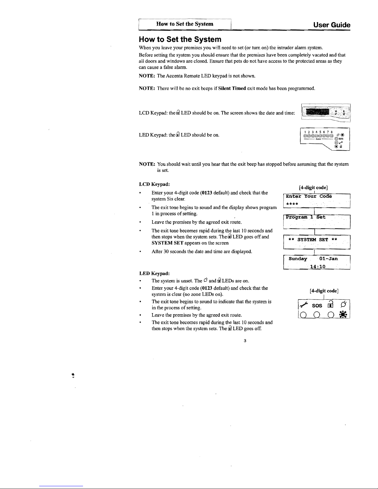
LCD Keypad: the
til
LED should
be
on. The screen shows the date and time:
-
12345678
LED Keypad: the
til
LED should be on.
@@@@@@@@
rJ@
-----@-
~
~
~<
I
~
NOTE: You should wait until you hear that the exit beep has stopped before assuming that the system
is
set.
LCD Keypad:
[4-digit code]
Enter your 4-digit code (0123 default) and check that the
system Sis clear.
The exit tone begins
to sound and the display shows program
1 in process
of
setting.
Leave the premises
by
the agreed exit route.
The exit tone becomes rapid during the last 10 seconds and
then stops when the system sets. The
til
LED goes
off
and
SYSTEM SET appears on the screen
After 30 seconds the date and time are displayed.
I
Your
Code
14:10
LED Keypad:
The system is unset. The
(J
and
til
LEDs are on.
Enter your 4-digit code (0123 default) and check that the
[4-digit code]
system is clear (no zone LEDs on).
The exit tone begins to sound to indicate that the system is
in the process
of
setting.
Leave the premises
by
the agreed exit route.
The exit tone becomes rapid during the last 10 seconds and
then stops when the system sets. The
til
LED goes off.
3
Page 5

--
How
to Unset the System
User
Guide
How to Unset the System
When you enter your premises you need to unset (tum off) the system.
LCD Keypad:
Sunday
01-Jan
Enter the premises by the agreed entry route. The system
produces an entry tone. The
rJ
LED is on and the
Iil
LED is
14:10
I
off, indicating that the system is set.
[ 4-digit code]
Enter your 4-digit code (0 123 default).
I
**
The system unsets with a double beep. The
Iil
LED comes
on, indicating that the system is unset.
After 30 seconds the system displays the date and time.
Ol-Jan
SYSTEM UNSET
14:10
LED Keypad:
Ii]
Enter the premises
by
the agreed entry route. The system
~
SOS
6
produces an entry tone. The
rJ
LED is on and the
Iil
LED is off,
indicating that the system is set.
[4-digit code]
Enter your 4-digit code
(0123 by default).
*=~
The system unsets with a double beep. The
ri1
LED comes on
6
indicating that the system
is
unset.
.
!i-
..
.
..
tt:
If
any Zone,
,?
(Tamper) or
sos
(Attack) LEDs come on then an alarm has occurred, and an intrusion
may have taken place. Seek assistance before investigating further as intruders may still be on the
premises. Then reset the system.
When
you
enter your premises
you
have a short period oftime, usually 30 seconds, to enter your code.
If
you fail
to
do this the system goes into alarm. Enter your code to stop the alarm.
4
Page 6
How to Part Set
User
Guide
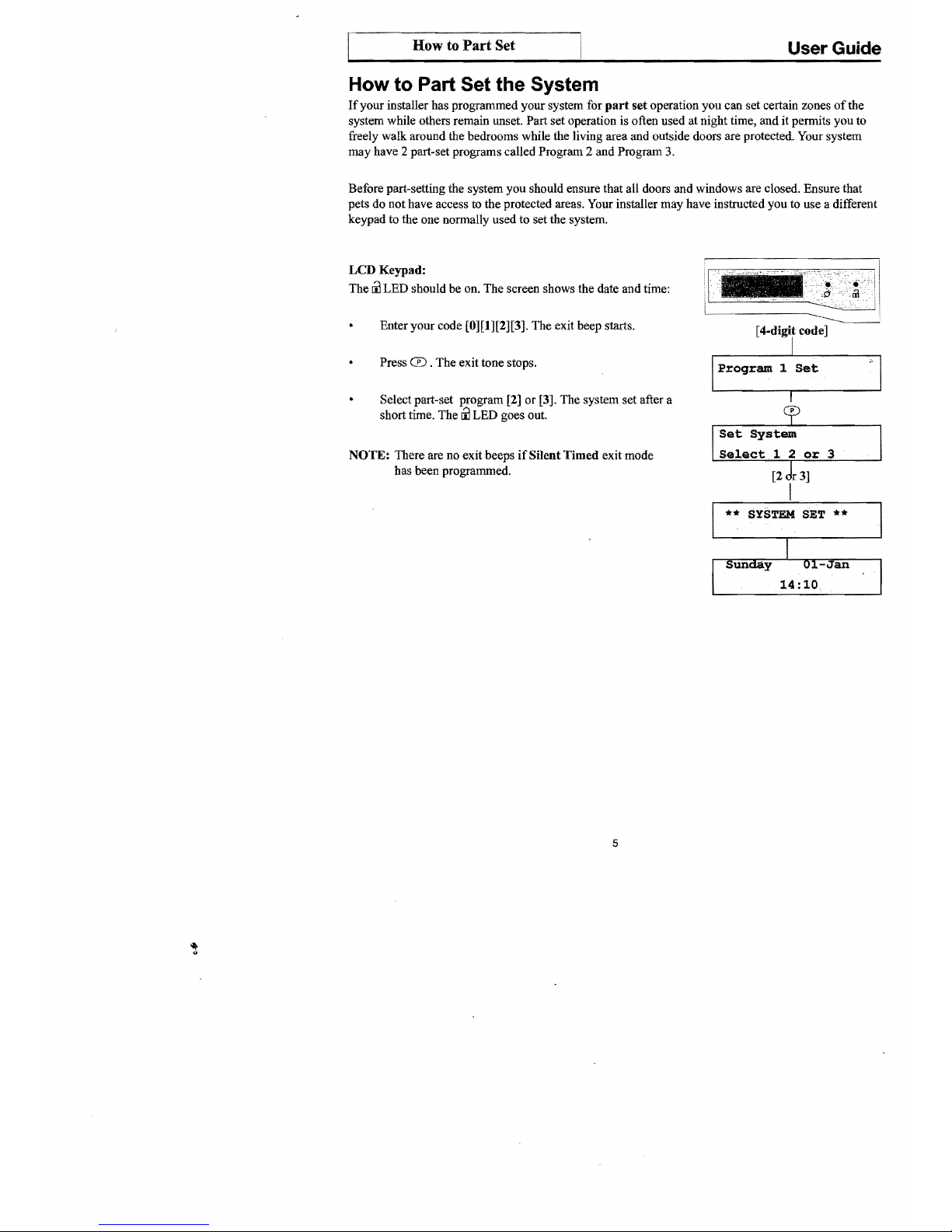
How to Part Set the System
If
your installer has programmed your system for part
set
operation you can set certain zones
of
the
system while others remain unset. Part set operation is often used at night time, and it permits you to
freely walk around the bedrooms while the living area and outside doors are protected. Your system
may have 2 part-set programs called Program 2 and Program 3.
Before part-setting the system you should ensure that all doors and windows are closed. Ensure that
pets do not have access to the protected areas. Your installer may have instructed you to use a different
keypad to the one normally used to set the system.
LCD
Keypad:
The
ill
LED should be on. The screen shows the date and time:
Enter your code [0][1][2][3]. The exit beep starts.
Press
CD
. The exit tone stops.
Select part-set program [2) or [3]. The system set after a
short time. The
ill
LED goes out.
NOTE: There are no exit beeps
if
Silent
Timed
exit mode
has been programmed.
I
Program 1 Set
"1
or
3
SYSTEM
SET **
5
Page 7

How to Silence an
Alarm··~
User Guide
LED
Keypad:
The
til
LED should be on.
Enter your code [0][1][2][3]. The exit beep starts.
Press the CD key. The exit tone stops and the zone LEDs
lto
3
come on.
Select part-set program [2]
or
[3]. The system sets after a
short time. The
til
LED goes out.
NOTE: There are no exit beeps
if
Silent Timed exit mode has been
programmed.
©sos
©.-"
I
@1iI
(6)~~(~~~
O'@
::.
[0][1][2][3] then CD
I
I
[2
or
3]
I
12345678
©©©©©©©©
O'@
__
__
©sos
"'~
©.-"
©1iI
How to Silence an Alarm and Reset the System
If
your system goes into alarm then be aware that intruders may
be in the premises. Seek assistance before investigating the
cause
of
the alarm.
LCD
Keypad:
Enter your code [0][ 1 ][2][3]. The alarm stops.
The
screen alternates, showing what caused the alarm
and
prompting for user reset.
When two
or
more alarms have occured, the first alarm
has
an
F below the zone number, Tamper
or
PA.
Subsequent alarms will have a
1 indicating where the
alarm has taken place.
Press
0.
The system resets and displays the date and time
if
there are no open Tampers,
PA
or
Fire zones to cause a
fault lockout.
The
system can be reset
by
the
user only ifthe installer
has programmed it to do so.
If
the message Engineer
Restore Required appears
on
screen then the user
must
contact the installer.
After
30
seconds the system displays the date and time.
6
Enter
Your
Code
I
[0][1][2][3]
Res~ored
by
User
Sunday
Oi-Jan
14:10
Page 8

How
to
Omit
Zones
User
Guide
LED
Keypad:
Enter your code [0][1][2][3].
The
alann
stops, and the Zone,
-?
or
sos LEDs come on to show the
[0][1][2][3]
cause
of
the alann.
NOTE: When
2
or
more LEDs are on, the flashing indicator shows the first
alann, and the steady indicators show the second and subsequent
alanns.
@ill
I
Press®
.
®
If
the Zone,
-?
or
® LEDs go out
and
the
00
LED
comes
on, the system has been reset.
If
any ofthe LEDs continue to flash then the system has been
programmed to
be
reset by the installer. In this case you must call the
installer to reset the system.
If
all LEDs light steady (not flashing), and the keypad stops working,
then the system has entered a fault-lockout. You must-call the installer
to rectifY this fault.
How to Omit Zones
If
you cannot set the
alann
system because a detector is faulty and in constant
alann
you
may
need
to
omit its zone from the alarm system.
A zone which has been omitted cannot cause an alann. Omitted
zones will
be
restored after the system is unset.
Before a zone can be omitted it has to be enabled
by
the installer as a Used
Zone
and as an
Omit
AUowzone.
LCD
Keypad:
[4-digit code]
Enter your [ 4-digit code] to start the exit procedure (for
I
more infonnation see
How to Set the System).
Program 1 Set
Press 8 and the exit beep tone stops, and the first
used zone that can
be
omitted appears on the display.
Press the zone [ number]
or
@ to
be
omitted.
The display now shows the zone as omitted.
If
a long
reject tone is heard, then the zone cannot
be
omitted.
cb
Press GO
or
allow the system to continue to set.
I
Program 1 Set
NOTE:
Zn
Zone number
**
SYSTEM
SET **
7
12345678
@@@@@@@@
C!
@
__,___
@sos:
@.-"
[Descriptor]
Omitted
Page 9

How to Quick Set
User Guide
LED Keypad:
Enter your [4-digit code] to start the exit procedure (for
more information see How to
Set the System).
Press 8 and the exit beep tone stops, and all LEOs for used
zones that can be omitted come on.
Press the zone [number] to be omitted. The LED now flashes to
show the zone as omitted.
If
a flat reject tone is heard, then the
zone cannot be omitted.
Press
Q)
or allow the system to set.
How to Quick Set the System
When you set the system you usually have about
30
seconds to exit the premises. This also means
that you need to wait 30 seconds for the system to set. You can reduce this time to
just
five seconds
by
carrying out a
Quick
Set.
Enter your [4-digit code] to start the exit procedure. The exit beep tone starts.
(For more information see
How
to
Set
the
System).
Press
Q)
to Quick Set the system and the exit beep tone changes to a more rapid tone.
The system sets in five seconds, and the exit tone stops.
Single Key Setting
If
enabled by the engineer, the setting process can be started by pressing Set, rather than entering a user
8
Page 10

O@
©sos
©
....
@Iil
How to Set Up Chime Mode
User Guide
How to Set Up Chime Mode
Chime is a low security facility for use when the system is unset.
It
is particularly useful in a shop to
warn
of
customers presence,
or
in a house to warn when a back door has been opened. When a Chime
zone detects movement the system produces a
brief
tw(}-tone sound, and the Zone LED comes on.
To
set any zone to Chime.
LCD Keypad:
The
lil
LED is on, indicating that the system is unset.
Press
ffi.
The screen shows the first zone that is
NO
already set up for Chime (possibly none).
[Number]
Press the zone [number] to toggle it in and out
of
chime.
YES
When you have finished using the Chime mode press
®
or
®
wait a few seconds for the display screen to the date and time.
I
Sunday
Ol-Jan
.
14:10
I
NOTE:
Zn
= Zone number
LED Keypad:
The
lil
LED
is
on, indicating that the system is unset.
Press
ffi.
The zone LEDs come on to show those
I
zones that are already set up for Chime (possibly none).
[Number]
I
Press the zone [
number]
to toggle it in and out
of
chime.
When you have finished using the Chime mode press
® or
wait a few seconds. The zone LED goes off.
9
Page 11

How to Change User Codes
User Guide
Changing Codes Using User 1
You should change your code regularly to prevent potential intruders from knowing your code. All
codes are 4-digits.
The
factory set code
is
[0][1][2][3]. User code I can only
be
changed
by
user
1.
To change user code:
LCD
Keypad:
o then [0][1][2][3]
Press
0 and then enter your code [0][1][2][3].
The
iil
I
LED goes
off
to indicate that you are in Programming
lo>walk
Test
mode. The first menu
Walk
Test
appears on the screen.
Press
[8]
on the keypad to enter User Set-Up.
8>Set
Up
User
[Number]
Press
[1]
or
[2] on the keypad to edit the required user.
[1]
or
[2]
Enter the new [ 4-digit code].
If
the code is accepted the
system produces a double beep.
If
it is rejected the code
may
already
be
in use and the system produce a long tone.
You must choose a different 4-digit code.
[
4-digit
code]
I
Upon the last keypress the code
is
saved.
I
Code
Saved
I
Press ® twice to exit Programming mode.
The
iil
®
LED
comes on and the screen displays the date
and
time.
I
Sunday
01-Jan
14:10
I
.
LED
Keypad:
o then [0][1][2][3]
Press 0 and then enter your code [0][1][2][3].
The./
LED comes on and the
iil
LED goes
off
to indicate that you
are in Programming mode.
12345678
©©©©©©©©
--"'~--©sos
(J
@
@
.....
I
©Iil
Press [8]
on
the keypad. LEDs 1 and 2 are
on
to
indicate
[y]
that you have two options, user I and user 2.
12345678
@@©©©©©© (J @
--'_--@$O$
Press [1]
or
[2] on the keypad to edit the required user.
@
.....
LEDs 1-4 are on.
©Iil
Enter the
new
[4-digit code]. Ifthe code is accepted the
system produces a double beep.
If
it
is
rejected the code
may already
be
in use
and
the system produces a long tone.
You
must
choose a different 4-digit code.
Upon the last keypress the code is saved. LEDs 1-4 are off.
Press
® twice to exit Programming mode.
The
iil LED
comes on
and
the
./
goes off.
10
[1]
or
[2]
then [4-digit code]
I
Page 12

c-------------How
to Change User Codes (contd) i
User
Guide
Changing Codes using User 2
Your
alann
system can have a second user code. You may find it useful to set up user code 2 for use by
a neighbour for use when you are on holiday. User code 2 operates like user code
1,
but it cannot be
used to change
or
delete user code
1.
To change user code 2:
LCD
Keypad:
Press CD and then enter user 2 [4-digit code]. The
III
LED goes
off
to indicate that you are in Programming
mode. The first menu Walk Test appears on the screen.
Press [8] to edit user 2.
Enter the
new
[4-digit code].
If
the code is accepted the
system produces a double beep.
If
it is rejected the code
may already be in use and the system produces a long
tone. You must choose a different 4-digit code.
Upon the last keypress the code is saved.
Press CD twice to exit Programming mode. The
III
LED comes on and the screen shows the date and time.
LED
Keypad:
Press CD
and
then enter user 2 [4-digit code].
The
"."..
LED comes on and the
III
LED goes
off
to indicate that
you
are in Programming mode.
Press the [8]
to edit user 2. LEDs 1-4
are
on.
Enter the new [4-digit code].
Ifthe
code is accepted the
system produces a double beep.
If
it is rejected the code
may already be in use and the system will produce a flat tone.
You must choose a different 4-digit code.
Upon the last keypress the code is saved. LEDs 1-4 are off.
Press CD twice to exit Programming mode. The
III
LED
comes on and the""'" goes off.
11
CD then [4-digit code]
I
I.o>walk
Test
I~~~
Code
I
[4-digit code]
I
I
Code
Saved
I
CD
I
Ol-Jan
I
Sunday
14:10
CD then [4-digit code]
<ii\(§I~~~<?!~9><Q)~
""
cJ
®
@sos
®
.....
I @cil
[8]
I
[
4-digit
code]
I
12345678
®®@®@@@@
cJ
®
--,,~--@sos
®
.....
I @cil
CD
.--_~I
__
----,
12345678
@@@@@@@@
cJ
®
--,._--@sos
@
.....
®Dl
Page 13

How
to
Delete User Code 2
User
Guide
How to Delete User Code 2
You
can
delete the second code to prevent it being used. User 1
or
user 2 can delete user code 2.
CD then [0][\][2][3]
To
delete user code 2 using user code 1
IO>Walk
Test
I
LCD
Keypad:
Press
CD
and then enter your code [0][1][2][3]. The
~
00
LED
goes
off
to indicate that you are in Programming
"
mode. The first menu
Walk
Test
appears
on
the screen.
s>set
Up
I)
I
.User
1
Press
[8]
on
the keypad to enter User Set-Up.
Press [2] to edit user code 2.
I~~~~
Code
I
Press G to delete user code 2.
G
I
I
Code
Deleted
The message
Code
Deleted
is displayed on the screen.
I
Press ® twice to exit Programming mode. The
00
LED
®
comes on and the screen displays the date and time.
I
01-Jan
I
Sunday
14:10
CD then [0][11[2][3]
LED
Keypad:
1~-:::-l
___
@$OS
Press CD and then enter your code [0][1][2][3]. The
00
@@@@@@:@@ c ® :
@i)~
;
LED goes
off
to indicate that you are in Programming
@UI
!
mode.
Press [8] on the keypad to enter User Set-Up. LEDs I
and 2 are on.
11
I.i
"
Press [2] to edit user code 2. LEDs 1-4 are on.
Press
G to delete user code 2.
User code 2 is deleted. LEDs 1-4 are off.
Press
® twice to exit Programming mode. The
00
LED
comes
on
and
the
.?
LED
goes off.
12
Page 14

@m
User
Guide
To delete user code 2 using user code 2
LCD
Keypad:
Press CD and then enter the user 2 [4-digit code].
CD then [4
j
digit
code]
The
til
LED goes
off
to indicate that you are in
Programming mode. The first menu
Walk
Test
appears
on
/o>walk
Test
the screen.
Press [8] on the keypad
to edit user code 2.
Press
8 to delete user code
2.
The
message
Code
Deleted is displayed on the screen.
Press
® twice to exit Programming mode.
The
til
LED
comes
on
and the screen displays the date and time.
LED
Keypad:
Press CD and then enter the user 2 [4-digit code]. The
®
I
Sunday
Ol-Jan
.
14
:10
I
CD then [4-digit code]
til
LED goes
off
to indicate that you are in Programming
mode.
I
Press [8]
on
the keypad
to
edit user code 2. LEDs 1-4 are
[8]
I
on.
12345678
@@@@@@@@
!J@
--L>_--@SOS
@.,....
Press 8 to delete user code 2.
User code 2 is deleted. LEDs 1-4 are off.
Press
® twice to exit Programming mode. The
ril
LED
comes on and
the.?
LED goes off.
13
Page 15

"
Duress Code
User Guide
Duress Code
Your alarm system can have a duress code. The Duress code
is
used in a hold-up situation where there
is pressure to set or unset the system. The Duress code operates like your normal code but in addition it
silently ·sends a signal to the Alarm Receiving Centre. The operator at the ARC may request the Police
to attend your premises.
The duress code can only set up, edited and deleted by the installer while in
Engineer program mode.
14
Page 16

I
1
How
to View the Event
i~g-J
User Guide
How to View the Event Log
LCD Keypad:
The
event log gives a display
of
all
the
events that have taken place. The events are arranged
by
date
and time. Up to 250 events can
be
stored in the memory. When
the
log reaches 250 events and another
event takes place, the oldest event drops out.
To view the event log:
Press
eD
and then enter your code [0][1][2][3].
Thew
LED
eDthen
[0][1)[2][3]
goes
off
to
indicate that you are in Programming mode.
The
first menu Walk Test appears on the screen.
I
lo>walk
Test
Press CD.
I
CD
Choose [1] for Event
Log
in LCD screen.
I .
Event
Log
~
1 LCD, 2
LED?
____
~
.
The last event (250) appears on
LCD
screen.
To go forward through the event log in sequence, press
G .
[ ]
To go back through
the
event log in sequence, press
00
.
Press
® twice to leave
the
menu.
Togo
to a specific event:
PresseD.
Key in the Event Number you want to see (e.g. 150).
Press
Q)
.
The
event appears on the LCD screen.
Press
Q)
again to see further details ofthe
event.
luser
4
Press
® twice to leave
the
menu option.
~
Cf
!C>View
Event
Log
~
15
2S0>ENG
ACCESS
08:44:03
17-Ma
Page 17

12345678
@@@@@@@@
(I
@
--_--@sos
@ ....
@1iJ
User Guide
How
to
Test
the
Alarm
System
2 =
LED
Keypad:
The LED keypad is limited to show the last eight set periods with the eighth being the oldest. Zone,
sos
and../'
LEOs are on, to show zone in alann . A flashing LED indicates the first zone in alann.
00
indicates the status ofthe panel at the time
of
the alann.
Press CD and then enter your code [0][1][2][3]. The
00
LED goes
CD
then [Q][I][2][3]
off
and
the../'
LED comes on to indicate that you are in
I
Programming mode.
Press
® to enter into Event Log menu. LEOs 1 and 2 are on.
Press
[2] for LED keypad. The first zone to activate is indicated
cr
by a flashing LED.
I
Press
[1
to
8]
for the desired event
or
® to go through
events
in
sequence.
Press CD twice to leave
the
menu.
How to Test Your Alarm system
You should check that your alann system still works correctly by periodically carrying out the alann
system tests described here.
How
to Test the Bell, Strobe and Internal Sounder
This function tests the alann function ofthe Bell, Strobe or Internal Sounder. Pressing the appropriate
key.
[1-3] toggle the function ON
or
OFF. Using the ® also selects the appropriate alann function.
Pressing [0] turns all alann outputs to OFF.
Pressing
(l)
toggles the selected
alann
output.
Pressing CD turns
off
all outputs and leaves the function.
The outputs are:
1 = Bell, 2 = Strobe, 3 = Sounder
NOTE:
To test the Low volume sounder enable option 3 only. To test for a high volume sounder
enable both options 2 and 3 together.
16
Page 18

r-;::------------~-l
I
~esting
the Alarm System (contd)
User
Guide
LCD
Keypad:
Press
(P)
and then enter your code [0][1][2][3]. The
Iil
LED
goes
off
to indicate that you are in Programming mode. The
first menu,
Walk
Test
appears on the screen.
Press
Gi0
for menu
Alarm
Test.
Press [1]
or
(P)
to
enter into first function
ON
or
OFF.
Press the
Gi0
or
number [2]
or
[3] for the other functions.
Press
®
to
leave the menu.
LED
keypad
Press
(P)
and then enter your code [0][1][2][3].
The
Iil
LED
goes
off
and
the
.r
LED comes
on
to indicate that you
are in Programming mode.
Press II} for menu
Alarm
Test.
Press [1] or 0 to toggle first function
ON
or
OFF.
Press number [2] and [3] for the other functions.
Press
® twice to exit Programming mode. The
Iil
LED
comes on and the
.r
LED
goes off.
17
(P)
then [0][1)[2][3]
I .
lo>walk
Test
Gi0
I
11>Alarm
Test
I
I
[1]
or0
I
01:
Bell
OFF
I
Gi0
or I[Number]
~trobe.
I
cp
!l>Alarm
Test
(P)
then [0][1)[2][3]
_.__.---L.I~__
-,
2345678
@@@~@@@l
ct!i
G=
-~~~I~
~:i'
[1]
I
Page 19

How to
do
a Walk Test
User
Guide
How to do a Walk Test
Walk around your property, and in
tum
cause each detector to go into alann. Also, open and close
all door and windows that are protected by the system. For each detector (including door or window
sensor) that is activated the system produces a series
of
beeps, and the associated zone is indicated on
the keypad.
NOTE: Do not test any Personal Attack, Fire
or
Tamper keys during the Walk Test since these are
still active and will cause a full alarm.
If
any ofthe tests fail, or you are unsure ofthe correct procedure, contact your installer
CD then [0][11[2][3]
LCD Keypad:
Press
CD
and then enter your code [0][l][2][3]. The
00
LED goes
off
to indicate that you are in Programming mode.
The first menu
Walk Test appears on the screen.
00r[0]
Press 0
or
[0]. Zones 1-8 have a zero (0)
below each
TP
number.
00
I
When a zone is successfully tested, number 1 replaces the
O.
®
Zones are added
to
the list as each one is activated.
I
l0>wal.k
Test
Press ®
to
leave the menu
or
0 to restart the Walk Test.
LED keypad
Press
CD
and then enter your code [0][1][2][3]. The
00
LED
CD then
[0][1][2][3]
goes
off
and
the./'
LED comes on to indicate that you are
in Programming mode,
Walk Test.
12345678
@@@@@@@@
o@
--"~--@SO$
@
....
Press 0 or [0]. Zones 1-8 are off.
I @Ol
o
When a zone is sucsessfully tested, the LED is on.
Zones are added to list as each one is activated.
Press
® to leave the menu
or
0 to restart the Walk Test.
18
Page 20

! How
to
Set Up tbe Time & Date J
User Guide
How to Set up the Time and Date
LCD
Keypad:
Press CD and then enter your code [0][1][2][3]. The
Iil
LED goes off, indicating that you are in Programming
mode.
The first menu
Walk
Test appears on the screen.
Press [4] and the
Time
and
Date
Screen appears.
The
Time
can be modified in hours, minutes and seconds
in the format HH:MM:SS. The number keys on the
keypad 0-9 are used for this function. As each digit
is
modified the cursor moves to the next one. When the time
is
correct press
Q)
to accept the change and move
to
the
next screen
or
to cancel the change press ® twice.
The
Date
can be changed in
day,
month, year format
DD-MM-
YY.
The number keys on the keypad 0-9 are used
for this function.
As each digit
is
modified the cursor moves to the next one.
When the date is correct press
Q)
to accept the change or to
cancel the change press
® twice.
LED
Keypad:
CD
then [0][1)[2)[3]
I
lo>walk
Test
I
[4]
Time
and
Date
Time?
13:46:17
I
Q)
Time
and
Date
Date?
17-05-06
Q)
I
14>set
Up
'rime
and
Date
If
required, the time and date can be entered as per the procedure for the LCD keypad. However no
information will be indicated on the LED keypad. The only indication on the LED keypad that you are
in menu 4,
Set
up
Time
and
Date,
is
that LEDs 1 to 6 on the LED Keypad will
be
ON.
19
Page 21

-----
Notes
-----
--~--~---.------------~-
...
----~--,,-.------~
....
----------
.------
..
-----------
.~----------.--------
20
Page 22

External Siren Time:
____________
_
Siren delay:
___________
_
Area
,Protected
Zone Name Program 1 Program 2 Program 3
Zone 1
Zone 2
Zone 3
Zone 4
ZoneS
Zone 6
Zone 7
Zone 8
T = Timed (EntryiExit Zone)
TI
= Time Inhibited (Access zone to keypad)
I
= Immediate
(E
The panels conform to the requirements
of
the European EMC and Low Voltage
directives, and
cany
the
CE
mark.
© Copyright Honeywell Security
EKZ014500A
Page 23

External Siren Time:
____________
_
Siren delay:
__________
_
Area
Protected
Zone Name
Program 1 Program 2 Program 3
Zone 1
Zone 2
Zone 3
Zone 4
Zone 5
Zone 6
Zone 7
Zone 8
T = Timed (EntryiExit Zone)
TI
= Time Inhibited (Access zone to keypad)
I
= Immediate
(€
Tile panels confonn
to
tile reqnirements
of
tile European EMC and Low Voltage
directives, and carry tile CE mark.
© Copyright Honeywell Security
EKZ014500A
 Loading...