

Honeywell Acuix IP Installation Manual

ACUIX™IP Series
Rugged Housing and Dome
Installation Guide
Document 800-02460 – Rev A – 08/08

Revisions
Issue Date Revisions
A 08/08 New document
2
Explanation of Symbols
WARNING! The exclamation point in a red octagon is a WARNING. Failure to take or
avoid a specific action could result in physical harm to a person or
irreparable damage to equipment.
ACUIX IP Rugged Housing and Dome Installation Guide
Caution The lightning flash with arrowhead symbol within an equilateral triangle alerts
the user to the presence of uninsulated dangerous voltage within the
enclosure of the product that may be of sufficient magnitude to constitute a
risk of electric shock to the person.
Caution The exclamation point in a yellow equilateral triangle is a Caution. Failure to
take or avoid a specified action could result in loss of data or damage to
equipment and may contain important operating and maintenance servicing
information.
FCC Compliance Statement
Information to the User: This equipment has been tested and found to comply with the limits for a Class B digital
device. Pursuant to Part 15 of the FCC Rules, these limits are designed to provide reasonable protection against
harmful interference in a residential installation. This equipment generates, uses, and can radiate radio frequency
energy and, if not installed and used in accordance with the instruction manual, may cause harmful interference to
radio communications. However, there is no guarantee that interference will not occur in a particular installation.
If this equipment does cause harmful interference to radio or television reception, which can be determined by turning
the equipment off and on, the user is encouraged to try to correct the interference. For example, try orienting or
relocating the receiving antenna, increasing the separation between the equipment and receiver, or connecting the
equipment to an outlet on a different circuit.
Document 800-02460 Rev A 3
08/08
ACUIX IP Rugged Housing and Dome Installation Guide
Changes or modifications not expressly approved by the party responsible for compliance
could void the user’s authority to operate the equipment.
Users of the product are responsible for checking and complying with all federal, state and
local laws and statutes concerning the monitoring and recording of video and audio signals.
Honeywell Video Systems shall not be held responsible for the use of this product in violation
of current laws and statutes.
Canadian Compliance Statement
This Class B digital apparatus complies with Canadian ICES-003.
Cet appareil numérique de la classe B est conforme à la norme NMB-003 du Canada.
Manufacturer’s Declaration of Conformance
North America
The equipment supplied with this guide conforms to UL60065, CAN/CSA C22.2 No. 60065:03.
Europe
The manufacturer declares that the equipment supplied with this guide is compliant with the essential protection
requirements of the EMC directive 2004/108/EC and the Low Voltage Directive LVD 2006/95/EC, conforming to the
requirements of standards EN 55022 for emissions, EN 50130-4 for immunity, and EN 60065 for Electrical Equipment
safety.
Australia
This Class B digital apparatus complies with Australian Communications Authority (ACA) C-Tick standards, supplier
number N219.
Document 800-02460 Rev A 4
08/08
ACUIX IP Rugged Housing and Dome Installation Guide
Warnings and Cautions
Read the following cautions and warnings prior to installation and use of this product.
All installations and servicing must be performed by qualified technical personnel and
must be in accordance with all national and local mechanical and electric codes.
To prevent injury, this apparatus must be securely attached to the wall/ceiling in
accordance with the installation instructions.
To prevent damage to the interface board, follow standard industry precautions for
electrostatic discharge sensitive devices.
Consider using a UPS source to ensure satisfactory performance.
Using replacement parts or accessories other than the original manufacturers may invalidate the
warranty.
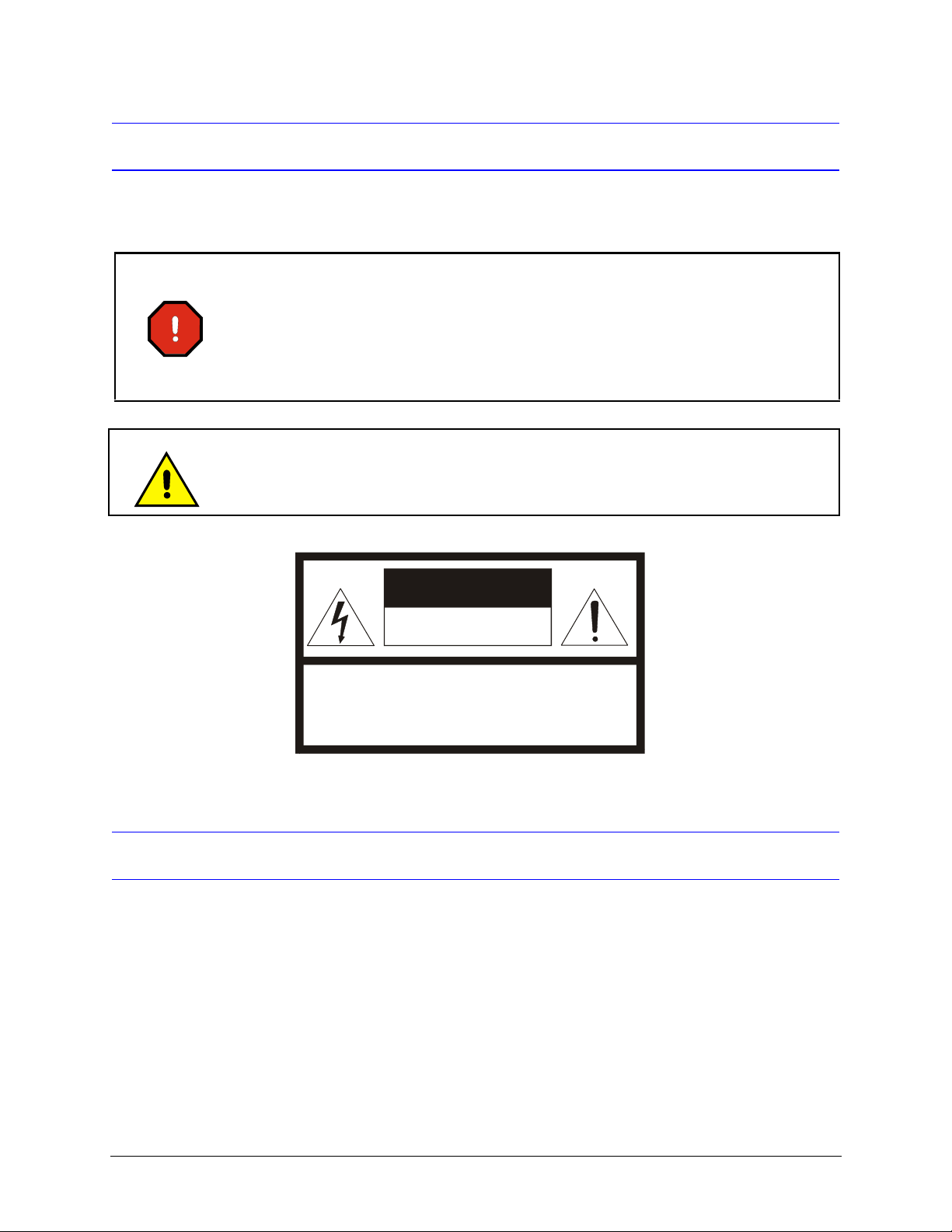
CAUTION
RISK OF ELECTRIC SHOCK
DO NOT OPEN
CAUTION: TO REDUCE THE RISK OF ELECTRIC SHOCK,
DO NOT REMOVE COVER (OR BACK).
NO USER-SERVICEABLE PARTS INSIDE.
REFER SERVICING TO QUALIFIED SERVICE PERSONNEL.
Important Safety Instructions
BEFORE OPERATING OR INSTALLING THE UNIT, READ AND FOLLOW ALL INSTRUCTIONS.
AFTER INSTALLATION, retain the safety and operating instructions for future reference
1. HEED WARNINGS - Adhere to all warnings on the unit and in the operating instructions.
Document 800-02460 Rev A 5
08/08

ACUIX IP Rugged Housing and Dome Installation Guide
2. INSTALLATION
• Install in accordance with the manufacturer’s instructions.
• Installation and servicing should be performed only by qualified and experienced technicians to conform to
all local codes and to maintain your warranty.
• Do not install the unit in an extremely hot or humid location, or in a place subject to dust or mechanical
vibration. The unit is not designed to be waterproof. Exposure to rain or water may damage the unit.
• Any wall or ceiling mounting of the product should follow the manufacturer’s instructions and use a
mounting kit approved or recommended by the manufacturer.
3. POWER SOURCES - This product should be operated only from the type of power source indicated on the
marking label. If you are not sure of the type of power supplied to your facility, consult your product dealer or
local power company.
4. HEAT - Situate away from items that produce heat or are heat sources such as radiators, heat registers, stoves,
or other products (including amplifiers).
5. MOUNTING SYSTEM - Use only with a mounting system recommended by the manufacturer, or sold with the
product.
6. ATTACHMENTS - Do not use attachments not recommended by the product manufacturer as they may result in
the risk of fire, electric shock, or injury to persons.
7. ACCESSORIES - Only use accessories specified by the manufacturer.
8. CLEANING - Do not use liquid cleaners or aerosol cleaners. Use a damp cloth for cleaning.
9. SERVICING - Do not attempt to service this unit yourself as opening or removing covers may expose you to
dangerous voltage or other hazards. Refer all servicing to qualified service personnel.
10. REPLACEMENT PARTS - When replacement parts are required, be sure the service technician has used
replacement parts specified by the manufacturer or have the same characteristics as the original part.
Unauthorized substitutions may result in fire, electric shock or other hazards.
Warranty and Service
Subject to the terms and conditions listed on the Product Warranty Card, during the warranty period Honeywell will
repair or replace, at its sole option, free of charge, any defective products returned prepaid. In the U.S.A. and Canada,
call 1.800.796.2288.
In the event you have a problem with any Honeywell Video product, please call Customer Service for assistance or to
request a Return Merchandise Authorization (RMA) number. Be sure to have the model and serial number, and the
nature of the problem available for the technical service representative. Prior authorization must be obtained for all
returns, exchanges, or credits. Items shipped to Honeywell without a clearly identified Return Merchandise
Authorization (RMA) number may be refused.
WEEE (Waste Electrical and Electronic Equipment). Correct disposal of this product
(applicable in the European Union and other European countries with separate collection
systems). This product should be disposed of, at the end of its useful life, as per applicable
local laws, regulations, and procedures
Document 800-02460 Rev A 6
08/08

Contents
About Using This Guide . . . . . . . . . . . . . . . . . . . . . . . . . . . . . . . . . . . . . . . . . . 9
Installation Overview . . . . . . . . . . . . . . . . . . . . . . . . . . . . . . . . . . . . . . . 10
Related Documents. . . . . . . . . . . . . . . . . . . . . . . . . . . . . . . . . . . . . . . . 11
Wiring and Power Cautions and Requirements . . . . . . . . . . . . . . . . . . . . . . . . . . . . . . 11
Wiring and Power Cautions. . . . . . . . . . . . . . . . . . . . . . . . . . . . . . . . . . . . 11
Recommended Wiring . . . . . . . . . . . . . . . . . . . . . . . . . . . . . . . . . . . . . . 12
Power Requirements . . . . . . . . . . . . . . . . . . . . . . . . . . . . . . . . . . . . . . . 12
Step 1: Connect the Field and Terminal Block Wiring . . . . . . . . . . . . . . . . . . . . . . . . . . . 13
About the Terminal Blocks (J1, J4 and J6) and Switch (SW1). . . . . . . . . . . . . . . . . . 13
Connecting the Wiring to the Housing Interface Board . . . . . . . . . . . . . . . . . . . . . 14
Step 2: Set Switches on the Scan Assembly Circuit Board . . . . . . . . . . . . . . . . . . . . . . . . 17
About the SW5 and SW6 DIP Switch Settings . . . . . . . . . . . . . . . . . . . . . . . . . . 17
Setting DIP Switches SW5 and SW6 . . . . . . . . . . . . . . . . . . . . . . . . . . . . . . . 17
Step 3: Mount the Rugged Housing Bracket . . . . . . . . . . . . . . . . . . . . . . . . . . . . . . . 19
Step 4: Mount the Housing to the Ceiling or Wall . . . . . . . . . . . . . . . . . . . . . . . . . . . . . 20
Step 5: Install the Scan Assembly into the Housing . . . . . . . . . . . . . . . . . . . . . . . . . . . . 21
Step 6: Install the Lower Dome onto the Housing . . . . . . . . . . . . . . . . . . . . . . . . . . . . . 22
Step 7: Install the ACUIX IP Software and Configure the Dome . . . . . . . . . . . . . . . . . . . . . . 22
ACUIX IP Rugged Housing and Dome Installation Guide
Document 800-02460 Rev A 7
08/08

Figures and Tables
Figures
Figure 1-1 ACUIX IP Housing Interface Board Layout . . . . . . . . . . . . . . . . . . . . . . . . . . 14
Figure 1-2 J6 Terminal Block Alarm Connection . . . . . . . . . . . . . . . . . . . . . . . . . . . . . 16
Figure 1-3 Ferrite Bead Installation Location. . . . . . . . . . . . . . . . . . . . . . . . . . . . . . . 16
Figure 1-4 Rugged Housing Cable Access Hole . . . . . . . . . . . . . . . . . . . . . . . . . . . . . 16
Figure 1-5 (A) PCB Location (B) DIP Switch Location (C) DIP Switch Example . . . . . . . . . . . . . 18
Figure 1-6 Rugged Housing Bracket Hole Dimensions . . . . . . . . . . . . . . . . . . . . . . . . . 20
Figure 1-7 Insert the Scan Assembly into the Housing. . . . . . . . . . . . . . . . . . . . . . . . . . 21
Figure 1-8 Rugged Housing - Lower Dome . . . . . . . . . . . . . . . . . . . . . . . . . . . . . . . 22
Tables
Table 1-1 Related Documents and External Links . . . . . . . . . . . . . . . . . . . . . . . . . . . . 11
Table 1-2 ACUIX IP Recommended Wiring . . . . . . . . . . . . . . . . . . . . . . . . . . . . . . . . 12
Table 1-3 Wire Gauge Required for Maximum Distance to Dome . . . . . . . . . . . . . . . . . . . . 12
Table 1-4 Power Supplies . . . . . . . . . . . . . . . . . . . . . . . . . . . . . . . . . . . . . . . . . 12
Table 1-5 ACUIX IP Terminal Strip Pins and Functions (J1 and J6) . . . . . . . . . . . . . . . . . . . 15
Table 1-6 ACUIX IP DIP Switch Settings (SW5 and SW6) . . . . . . . . . . . . . . . . . . . . . . . . 17
8
 Loading...