

Honeywell ACUIX, ACUIX HDCFP0000, ACUIX HDCGN0000, ACUIX HDCGP0000 User Manual

ACUIX™
High Speed Dome
User Manual
Document 800-01023 – Rev A – 02/08

Revisions
Issue Date Revisions
1.00 05/07 New document
1.01 05/07 Revised document (HJZTP privacy zone revision)
A 02/08 Document p/n changed from 900.0849 rev 1.01. Removed 23X WDR & TDN (Hitachi
VK-S454R) camera, added 18X Color (Sony FCB-48C), 18X TDN (Sony FCB-490D)
and 26X WDR & TDN (Sony FCB-990D) cameras. Added Class A warning to p. 3.

FCC Compliance Statement
Information to the User: This equipment has been tested and found to comply with the limits for a Class B digital device.
Pursuant to Part 15 of the FCC Rules, these limits are designed to provide reasonable protection against harmful
interference in a residential installation. This equipment generates, uses, and can radiate radio frequency energy and,
if not installed and used in accordance with the instruction manual, may cause harmful interference to radio
communications. However, there is no guarantee that interference will not occur in a particular installation.
If this equipment does cause harmful interference to radio or television reception, which can be determined by turning
the equipment off and on, the user is encouraged to try to correct the interference. For example, try orienting or
relocating the receiving antenna, increasing the separation between the equipment and receiver, or connecting the
equipment to an outlet on a different circuit.
Caution Changes or modifications not expressly approved by the party responsible for compliance could void the
user's authority to operate the equipment.
Users of the product are responsible for checking and complying with all federal, state and local
laws and statutes concerning the monitoring and recording of video and audio signals.
Honeywell Video Systems shall not be held responsible for the use of this product in violation of
current laws and statutes.
Canadian Compliance Statement
This Class B digital apparatus complies with Canadian ICES-003.
Cet appareil numérique de la classe B est conforme à la norme NMB-003 du Canada.
Manufacturer’s Declaration of Conformance
The manufacturer declares that the equipment supplied with this guide is compliant with the essential protection
requirements of the EMC directive 89/336/EEC and the Low Voltage Directive LVD 73/23 EEC, conforming to the
requirements of standards EN 55022 for emissions, EN 50130-4 for immunity, and EN 60065 for Electrical Equipment
safety.
Document 800-01023 Rev A 3
02/08
Explanation Of Graphical Objects
The lightning flash with arrowhead symbol within an equilateral triangle is intended to alert the user to the
presence of uninsulated "dangerous voltage" within the enclosure of the product that may be of sufficient
magnitude to constitute a risk of electric shock to the person.
The exclamation point within an equilateral triangle is intended to alert the user to the presence of
important operating and maintenance servicing instructions in the literature accompany the product.
Important Safety Instructions
READ INSTRUCTIONS - All safety and operating instructions should be read before the unit is operated.
1. RETAIN INSTRUCTIONS - The safety and operating instructions should be retained for future reference.
2. HEED WARNINGS - All warnings on the unit and in the operating instructions should be adhered to.
3. FOLLOW INSTRUCTIONS - All operating and use instructions should be followed.
4. CLEANING - Unplug the unit from the outlet before cleaning. Do not use liquid cleaners or aerosol cleaners. Use
a damp cloth for cleaning.
5. ATTACHMENTS - Do not use attachments not recommended by the product manufacturer as they may result in
the risk of fire, electric shock, or injury to persons.
6. ACCESSORIES - Only use accessories specified by the manufacturer. Do not place this product on an unstable
cart, stand, tripod, bracket, or table. The product may fall, causing serious injury to a child or adult and serious
damage to the equipment. Use only with a cart, stand, tripod, bracket, or table recommended by the
manufacturer, or sold with the product. Any mounting of the product should follow the manufacturer's
instructions and should use a mounting accessory recommended by the manufacturer. Wall or shelf mounting
should follow the manufacturer's instructions and should use a mounting kit approved by the manufacturer.
7. A product and cart combination should be moved with care. Quick stops, excessive force, and uneven surfaces
may cause the product and cart combination to overturn.
8. POWER SOURCES - This product should be operated only from the type of power source indicated on the
marking label. If you are not sure of the type of power supplied to your facility, consult your product dealer or
local power company.
9. OVERLOADING - Do not overload outlets and extension cords as this can result in a risk of fire or electric shock.
10. POWER-CORD PROTECTION - Power supply cords should be routed so that they are not likely to be walked on
or pinched by items placed upon or against them, paying particular attention to cords, plugs, and convenience
receptacles.
11. SERVICING - Do not attempt to service this unit yourself as opening or removing covers may expose you to
dangerous voltage or other hazards. Refer all servicing to qualified service personnel.
4
12. DAMAGE REQUIRING SERVICE - Unplug the unit from the outlet and refer servicing to qualified service
personnel under the following conditions:
a. When the power-supply cord or plug is damaged.
b. If liquid has been spilled, or objects have fallen into the unit.
c. If the unit has been exposed to rain or moisture.
d. If the unit does not operate normally by following the operating instructions. Adjust only those controls that
are covered by the operating instructions as an improper adjustment of other controls may result in damage
and will often require extensive work by a qualified technician to restore the unit to its normal operation.
e. If the unit has been dropped or the enclosure has been damaged.
f. When the unit exhibits a distinct change in performance - this indicates a need for service.
13. REPLACEMENT PARTS - When replacement parts are required, be sure the service technician has used
replacement parts specified by the manufacturer or have the same characteristics as the original part.
Unauthorized substitutions may result in fire, electric shock or other hazards.
14. SAFETY CHECK - Upon completion of any service or repairs to this unit, ask the service technician to perform
safety checks to determine that the unit is in proper operating condition.
15. LIGHTNING AND POWER LINE SURGES - For added protection of this unit when it is left unattended and unused
for long periods of time, unplug it from the wall outlet and disconnect the cable system. This will prevent damage
to the unit due to lightning and power-line surges.
16. HEAT - The product should be situated away from heat sources such as radiators, heat registers, stoves, or other
products (including amplifiers) that produce heat.
17. INSTALLATION - Install in accordance with the manufacturer’s instructions. Do not install the unit in an extremely
hot or humid location, or in a place subject to dust or mechanical vibration. The unit is not designed to be
waterproof. Exposure to rain or water may damage the unit.
Prior to installation and use of this product, please observe the following cautions and warnings.
Caution
CAUTION
RISK OF ELECTRIC SHOCK
DO NOT OPEN
CAUTION: TO REDUCE THE RISK OF ELECTRIC SHOCK,
DO NOT REMOVE COVER (OR BACK).
NO USER-SERVICEABLE PARTS INSIDE.
REFER SERVICING TO QUALIFIED SERVICE PERSONNEL.
Document 800-01023 Rev A 5
02/08
Warning
Warning! Installation and servicing must be performed by qualified personnel in accordance
with current IEE wiring regulations.
Warning! The PSU must be wired to a double pole fuse spur with 3mm separation. The 3A
fuse spur must be located close to the PSU.
Warning! Using replacement parts or accessories other than the original manufacturers may
invalidate the warranty.
Warning! To prevent injury, this apparatus must be securely attached to the wall/ceiling in
accordance with the installation instructions.
6

ACUIX High Speed Dome User Manual
Contents
About This Document. . . . . . . . . . . . . . . . . . . . . . . . . . . . . . . . . . . . . . . . . . . . 15
Overview of Contents. . . . . . . . . . . . . . . . . . . . . . . . . . . . . . . . . . . . . . . . . . . 15
Related Documents . . . . . . . . . . . . . . . . . . . . . . . . . . . . . . . . . . . . . . . . . . . 16
1 Installing the Pan and Tilt Camera Assembly and Lower Dome . . . . . . . . . . . . . . . . . . 17
Introduction . . . . . . . . . . . . . . . . . . . . . . . . . . . . . . . . . . . . . . . . . . . . . . . . . 17
Models . . . . . . . . . . . . . . . . . . . . . . . . . . . . . . . . . . . . . . . . . . . . . . . . . . . 17
Installing the Pan and Tilt Camera Assembly . . . . . . . . . . . . . . . . . . . . . . . . . . . . . . . 18
Installing the Lower Dome . . . . . . . . . . . . . . . . . . . . . . . . . . . . . . . . . . . . . . . . .20
Indoor or Outdoor Pendant. . . . . . . . . . . . . . . . . . . . . . . . . . . . . . . . . . . . 20
2 Switch Settings . . . . . . . . . . . . . . . . . . . . . . . . . . . . . . . . . . . . . . . . . . . . 21
Protocol Settings . . . . . . . . . . . . . . . . . . . . . . . . . . . . . . . . . . . . . . . . . . . . . . 22
Baud Rate. . . . . . . . . . . . . . . . . . . . . . . . . . . . . . . . . . . . . . . . . . . . . . . . . . 23
Parity . . . . . . . . . . . . . . . . . . . . . . . . . . . . . . . . . . . . . . . . . . . . . . . . . . . . 24
Sample Switch Settings . . . . . . . . . . . . . . . . . . . . . . . . . . . . . . . . . . . . . . . . . . 24
Honeywell Diamond . . . . . . . . . . . . . . . . . . . . . . . . . . . . . . . . . . . . . . . 24
VCL - RS485 . . . . . . . . . . . . . . . . . . . . . . . . . . . . . . . . . . . . . . . . . . . 25
IntelliBus™ . . . . . . . . . . . . . . . . . . . . . . . . . . . . . . . . . . . . . . . . . . . . 25
Camera Address Settings . . . . . . . . . . . . . . . . . . . . . . . . . . . . . . . . . . . . . . . . . 25
Address Examples . . . . . . . . . . . . . . . . . . . . . . . . . . . . . . . . . . . . . . . . 26
DIP Switch Address Override. . . . . . . . . . . . . . . . . . . . . . . . . . . . . . . . . . . 26
Factory Defaults . . . . . . . . . . . . . . . . . . . . . . . . . . . . . . . . . . . . . . . . . . . . . . 26
Restore Factory Defaults . . . . . . . . . . . . . . . . . . . . . . . . . . . . . . . . . . . . . 27
RJ45 Ethernet Connection . . . . . . . . . . . . . . . . . . . . . . . . . . . . . . . . . . . . . . . . . 27
3 Operation and Programming with Honeywell Diamond Protocol . . . . . . . . . . . . . . . . . . 29
Introduction . . . . . . . . . . . . . . . . . . . . . . . . . . . . . . . . . . . . . . . . . . . . . . . . . 29
HEGS5000/5001 Controller . . . . . . . . . . . . . . . . . . . . . . . . . . . . . . . . . . . . . . . . 29
Power Up . . . . . . . . . . . . . . . . . . . . . . . . . . . . . . . . . . . . . . . . . . . . . 29
Reset ACUIX . . . . . . . . . . . . . . . . . . . . . . . . . . . . . . . . . . . . . . . . . . . 30
Manual Control . . . . . . . . . . . . . . . . . . . . . . . . . . . . . . . . . . . . . . . . . . 30
18X Color Camera (FCB-EX48C) . . . . . . . . . . . . . . . . . . . . . . . . . . . . . . . . . 33
18X True Day/Night Camera with Wide Dynamic Range (FCB-EX490D) . . . . . . . . . . . . 33
26X True Day/Night Camera with Wide Dynamic Range (FCB-EX990D) . . . . . . . . . . . . 33
35X True Day/Night Camera with Wide Dynamic Range, Progressive Scanning and Image Stabi-
lization (VK-S654) . . . . . . . . . . . . . . . . . . . . . . . . . . . . . . . . . . . . . . . . . 34
Freeze and Unfreeze Video. . . . . . . . . . . . . . . . . . . . . . . . . . . . . . . . . . . . 35
Flashback Operation . . . . . . . . . . . . . . . . . . . . . . . . . . . . . . . . . . . . . . . 35
NightShot Mode . . . . . . . . . . . . . . . . . . . . . . . . . . . . . . . . . . . . . . . . . 36
Alarm Operation . . . . . . . . . . . . . . . . . . . . . . . . . . . . . . . . . . . . . . . . . 36
Find Home . . . . . . . . . . . . . . . . . . . . . . . . . . . . . . . . . . . . . . . . . . . . 37
Presets . . . . . . . . . . . . . . . . . . . . . . . . . . . . . . . . . . . . . . . . . . . . . . 38
Preset Tours . . . . . . . . . . . . . . . . . . . . . . . . . . . . . . . . . . . . . . . . . . . 43
Rev A Document 800-01023
7
02/08

Contents
Mimic Tours. . . . . . . . . . . . . . . . . . . . . . . . . . . . . . . . . . . . . . . . . . . . 47
Sector IDs . . . . . . . . . . . . . . . . . . . . . . . . . . . . . . . . . . . . . . . . . . . . . 49
Privacy Zones. . . . . . . . . . . . . . . . . . . . . . . . . . . . . . . . . . . . . . . . . . . 51
HJTZP Controller . . . . . . . . . . . . . . . . . . . . . . . . . . . . . . . . . . . . . . . . . . . . . . 54
Power Up . . . . . . . . . . . . . . . . . . . . . . . . . . . . . . . . . . . . . . . . . . . . . 54
Reset ACUIX . . . . . . . . . . . . . . . . . . . . . . . . . . . . . . . . . . . . . . . . . . . 54
Manual Control . . . . . . . . . . . . . . . . . . . . . . . . . . . . . . . . . . . . . . . . . . 54
Freeze/Unfreeze Video . . . . . . . . . . . . . . . . . . . . . . . . . . . . . . . . . . . . . . 56
Flashback Operation . . . . . . . . . . . . . . . . . . . . . . . . . . . . . . . . . . . . . . . 56
NightShot Mode . . . . . . . . . . . . . . . . . . . . . . . . . . . . . . . . . . . . . . . . . 56
Alarm Operation . . . . . . . . . . . . . . . . . . . . . . . . . . . . . . . . . . . . . . . . . 56
Find Home . . . . . . . . . . . . . . . . . . . . . . . . . . . . . . . . . . . . . . . . . . . . 57
Presets . . . . . . . . . . . . . . . . . . . . . . . . . . . . . . . . . . . . . . . . . . . . . . 57
Preset Tours . . . . . . . . . . . . . . . . . . . . . . . . . . . . . . . . . . . . . . . . . . . 58
Mimic Tours. . . . . . . . . . . . . . . . . . . . . . . . . . . . . . . . . . . . . . . . . . . . 58
Sector IDs . . . . . . . . . . . . . . . . . . . . . . . . . . . . . . . . . . . . . . . . . . . . . 59
Privacy Zones. . . . . . . . . . . . . . . . . . . . . . . . . . . . . . . . . . . . . . . . . . . 59
4 Operation and Programming with Honeywell VCL Protocol . . . . . . . . . . . . . . . . . . . . 61
Introduction . . . . . . . . . . . . . . . . . . . . . . . . . . . . . . . . . . . . . . . . . . . . . . . . . 61
Power Up . . . . . . . . . . . . . . . . . . . . . . . . . . . . . . . . . . . . . . . . . . . . . . . . . . 61
Reset ACUIX . . . . . . . . . . . . . . . . . . . . . . . . . . . . . . . . . . . . . . . . . . . . . . . . 62
Manual Control . . . . . . . . . . . . . . . . . . . . . . . . . . . . . . . . . . . . . . . . . . . . . . . 62
Lens Control . . . . . . . . . . . . . . . . . . . . . . . . . . . . . . . . . . . . . . . . . . . 63
Freeze/Unfreeze Video—Preset 95 . . . . . . . . . . . . . . . . . . . . . . . . . . . . . . . . . . . . 63
Flashback Operation—Preset 96 . . . . . . . . . . . . . . . . . . . . . . . . . . . . . . . . . . . . . 64
NightShot Mode—Preset 94 . . . . . . . . . . . . . . . . . . . . . . . . . . . . . . . . . . . . . . . . 64
Find Home . . . . . . . . . . . . . . . . . . . . . . . . . . . . . . . . . . . . . . . . . . . . . . . . . 64
Presets . . . . . . . . . . . . . . . . . . . . . . . . . . . . . . . . . . . . . . . . . . . . . . . . . . . 64
Program Preset . . . . . . . . . . . . . . . . . . . . . . . . . . . . . . . . . . . . . . . . . . 66
Recall Preset . . . . . . . . . . . . . . . . . . . . . . . . . . . . . . . . . . . . . . . . . . . 66
Preset Tours . . . . . . . . . . . . . . . . . . . . . . . . . . . . . . . . . . . . . . . . . . . . . . . . 66
Run Preset Tour. . . . . . . . . . . . . . . . . . . . . . . . . . . . . . . . . . . . . . . . . . 68
Stop a Preset Tour . . . . . . . . . . . . . . . . . . . . . . . . . . . . . . . . . . . . . . . . 68
Sector IDs. . . . . . . . . . . . . . . . . . . . . . . . . . . . . . . . . . . . . . . . . . . . . . . . . . 69
Privacy Zones. . . . . . . . . . . . . . . . . . . . . . . . . . . . . . . . . . . . . . . . . . . . . . . . 69
Mimic Tours. . . . . . . . . . . . . . . . . . . . . . . . . . . . . . . . . . . . . . . . . . . . . . . . . 71
Programming Mimic Tours . . . . . . . . . . . . . . . . . . . . . . . . . . . . . . . . . . . . 71
Mimic Tour Operation. . . . . . . . . . . . . . . . . . . . . . . . . . . . . . . . . . . . . . . 72
Deleting Privacy Zones, Presets, Preset Tours, and Sectors . . . . . . . . . . . . . . . . . . 72
5 Operation and Programming with IntelliBus™ Protocol. . . . . . . . . . . . . . . . . . . . . . . 75
Factory Default Switch Settings . . . . . . . . . . . . . . . . . . . . . . . . . . . . . . . . . . . . . . 75
Configuration Upload/Download . . . . . . . . . . . . . . . . . . . . . . . . . . . . . . . . . . . . . . 76
Configuration Default . . . . . . . . . . . . . . . . . . . . . . . . . . . . . . . . . . . . . . . . . . . . 76
Configuration Data Saving . . . . . . . . . . . . . . . . . . . . . . . . . . . . . . . . . . . . . . . . . 76
Firmware Upgrade . . . . . . . . . . . . . . . . . . . . . . . . . . . . . . . . . . . . . . . . . . . . .77
6 ACUIX Password Feature. . . . . . . . . . . . . . . . . . . . . . . . . . . . . . . . . . . . . . . 79
Enabling the Password Feature . . . . . . . . . . . . . . . . . . . . . . . . . . . . . . . . . . . . . . 79
Logging On . . . . . . . . . . . . . . . . . . . . . . . . . . . . . . . . . . . . . . . . . . . . . . . . .80
Changing the 4-Digit PIN . . . . . . . . . . . . . . . . . . . . . . . . . . . . . . . . . . . . . . . . . . 80
Resetting Privacy Zone Password (Diamond or IntelliBus Protocols) . . . . . . . . . . . . . . . . . . . 81
Delete Privacy Zone Programming. . . . . . . . . . . . . . . . . . . . . . . . . . . . . . . . . . . . . 82
7 On-Screen Setup Menus . . . . . . . . . . . . . . . . . . . . . . . . . . . . . . . . . . . . . . . 83
Introduction . . . . . . . . . . . . . . . . . . . . . . . . . . . . . . . . . . . . . . . . . . . . . . . . . 83
Rev A Document 800-01023
8
02/08

ACUIX High Speed Dome User Manual
Control/Video Requirements . . . . . . . . . . . . . . . . . . . . . . . . . . . . . . . . . . . . . . . . 83
Honeywell Diamond Protocol . . . . . . . . . . . . . . . . . . . . . . . . . . . . . . . . . . . . . . . 84
Honeywell VCL Protocol . . . . . . . . . . . . . . . . . . . . . . . . . . . . . . . . . . . . . . . . . .85
Honeywell VCL Coax Control Protocol. . . . . . . . . . . . . . . . . . . . . . . . . . . . . . . . . . . 86
3rd Party Protocols . . . . . . . . . . . . . . . . . . . . . . . . . . . . . . . . . . . . . . . . . . . . . 87
Menu Tree . . . . . . . . . . . . . . . . . . . . . . . . . . . . . . . . . . . . . . . . . . . . . . . . . 88
Main Menu . . . . . . . . . . . . . . . . . . . . . . . . . . . . . . . . . . . . . . . . . . . . . . . . . 89
Selecting the Language . . . . . . . . . . . . . . . . . . . . . . . . . . . . . . . . . . . . . 89
Display Options . . . . . . . . . . . . . . . . . . . . . . . . . . . . . . . . . . . . . . . . . . 89
Control Options . . . . . . . . . . . . . . . . . . . . . . . . . . . . . . . . . . . . . . . . . . 92
Diagnostic Options . . . . . . . . . . . . . . . . . . . . . . . . . . . . . . . . . . . . . . . 102
Camera Options, 18X WDR & True Day/Night and 26X WDR, True/Day Night Camera
(FCB-EX490D and FCB-EX990D Respectively) . . . . . . . . . . . . . . . . . . . . . . . . 105
Camera Options, 35X WDR & True Day/Night Camera with Image Stabilization and Motion De-
tection
(VK-S654) . . . . . . . . . . . . . . . . . . . . . . . . . . . . . . . . . . . . . . . . . . . . 110
Function Programming . . . . . . . . . . . . . . . . . . . . . . . . . . . . . . . . . . . . . 116
Enhanced Settings . . . . . . . . . . . . . . . . . . . . . . . . . . . . . . . . . . . . . . . 123
Appendix A Troubleshooting . . . . . . . . . . . . . . . . . . . . . . . . . . . . . . . . . . . . .127
Technical Support . . . . . . . . . . . . . . . . . . . . . . . . . . . . . . . . . . . . . . . . . . . . 127
Problem: No Video . . . . . . . . . . . . . . . . . . . . . . . . . . . . . . . . . . . . . . . . . . . . 127
Problem: General Video Problems (Video Over UTP Only) . . . . . . . . . . . . . . . . . . . . . . . 128
Video is Inverted . . . . . . . . . . . . . . . . . . . . . . . . . . . . . . . . . . . . . . . . 128
Video is Poor . . . . . . . . . . . . . . . . . . . . . . . . . . . . . . . . . . . . . . . . . . 128
Problem: Video, But No Control . . . . . . . . . . . . . . . . . . . . . . . . . . . . . . . . . . . . . 129
Problem: Lens Out of Optical Focus . . . . . . . . . . . . . . . . . . . . . . . . . . . . . . . . . . . 130
Problem: Cannot Find Home or Does Not Go to a Preset. . . . . . . . . . . . . . . . . . . . . . . . 130
Problem: Pan and Tilt is Jerky . . . . . . . . . . . . . . . . . . . . . . . . . . . . . . . . . . . . . . 130
Problem: Video Zooms For No Reason . . . . . . . . . . . . . . . . . . . . . . . . . . . . . . . . . 131
Appendix B Specifications . . . . . . . . . . . . . . . . . . . . . . . . . . . . . . . . . . . . . .133
ACUIX Housings . . . . . . . . . . . . . . . . . . . . . . . . . . . . . . . . . . . . . . . . . . . . . 133
ACUIX Cameras . . . . . . . . . . . . . . . . . . . . . . . . . . . . . . . . . . . . . . . . . . . . . 134
Pan and Tilt Specifications . . . . . . . . . . . . . . . . . . . . . . . . . . . . . . . . . . . . . . . . 135
Operating/Programming Specifications . . . . . . . . . . . . . . . . . . . . . . . . . . . . . . . . . 136
ACUIX Lower Dome . . . . . . . . . . . . . . . . . . . . . . . . . . . . . . . . . . . . . . . . . . . 137
Regulatory Specifications . . . . . . . . . . . . . . . . . . . . . . . . . . . . . . . . . . . . . . . . 137
Appendix C Pelco Emulation . . . . . . . . . . . . . . . . . . . . . . . . . . . . . . . . . . . . .139
Purpose. . . . . . . . . . . . . . . . . . . . . . . . . . . . . . . . . . . . . . . . . . . . . . . . . . 139
ACUIX Mimic Tour Operation. . . . . . . . . . . . . . . . . . . . . . . . . . . . . . . . . . . . . . . 139
Appendix D Digital Video Recorder Integration . . . . . . . . . . . . . . . . . . . . . . . . . . .141
Purpose. . . . . . . . . . . . . . . . . . . . . . . . . . . . . . . . . . . . . . . . . . . . . . . . . . 141
DVR and Camera protocols . . . . . . . . . . . . . . . . . . . . . . . . . . . . . . . . . . . . . . . 141
Index. . . . . . . . . . . . . . . . . . . . . . . . . . . . . . . . . . . . . . . . . . . . . . . . . . . . 143
Rev A Document 800-01023
9
02/08

Contents
Rev A Document 800-01023
10
02/08

ACUIX High Speed Dome User Manual
Figures
Figure 1-1 ACUIX Pan and Tilt Camera Assembly . . . . . . . . . . . . . . . . . . . . . . . . . . . . 18
Figure 1-2 ACUIX Housing . . . . . . . . . . . . . . . . . . . . . . . . . . . . . . . . . . . . . . . . 19
Figure 1-3 ACUIX Pan and Tilt Camera Assembly Locking Rails. . . . . . . . . . . . . . . . . . . . . 19
Figure 1-4 Pendant Lower Dome Installation . . . . . . . . . . . . . . . . . . . . . . . . . . . . . . . 20
Figure 2-1 ACUIX Pan and Tilt Camera Assembly . . . . . . . . . . . . . . . . . . . . . . . . . . . . 21
Figure 2-2 Location of DIP and Rotary Switches on Main Board . . . . . . . . . . . . . . . . . . . . . 21
Figure 3-1 Sectors IDs. . . . . . . . . . . . . . . . . . . . . . . . . . . . . . . . . . . . . . . . . . . 49
Figure 3-2 Sector ID Coordinates . . . . . . . . . . . . . . . . . . . . . . . . . . . . . . . . . . . . . 50
Rev A Document 800-01023
11
02/08

Figures
Rev A Document 800-01023
12
02/08

ACUIX High Speed Dome User Manual
Tables
Table 1-1 ACUIX Pan and Tilt Camera Assembly Model Numbers. . . . . . . . . . . . . . . . . . . . 17
Table 2-1 DIP Switch SW5 ACUIX Protocol Settings . . . . . . . . . . . . . . . . . . . . . . . . . . . 22
Table 2-2 DIP Switch SW6 ACUIX Baud Rate Settings . . . . . . . . . . . . . . . . . . . . . . . . . . 23
Table 2-3 DIP Switch SW6 ACUIX Parity Settings. . . . . . . . . . . . . . . . . . . . . . . . . . . . . 24
Table 2-4 ACUIX Camera Addresses . . . . . . . . . . . . . . . . . . . . . . . . . . . . . . . . . . . 25
Table 3-1 HEGS5000 Joystick Operation . . . . . . . . . . . . . . . . . . . . . . . . . . . . . . . . . 31
Table 3-2 HEGS5000/5001 Camera Lens Control . . . . . . . . . . . . . . . . . . . . . . . . . . . . 32
Table 3-3 35X Camera Feature Dependencies . . . . . . . . . . . . . . . . . . . . . . . . . . . . . . 35
Table 3-4 Pre-programmed Presets. . . . . . . . . . . . . . . . . . . . . . . . . . . . . . . . . . . . 38
Table 3-5 Program Preset Menu Commands . . . . . . . . . . . . . . . . . . . . . . . . . . . . . . . 39
Table 3-6 Preset Title Operation. . . . . . . . . . . . . . . . . . . . . . . . . . . . . . . . . . . . . . 41
Table 3-7 Still Preset Operation . . . . . . . . . . . . . . . . . . . . . . . . . . . . . . . . . . . . . . 42
Table 3-8 Preset Tour Commands . . . . . . . . . . . . . . . . . . . . . . . . . . . . . . . . . . . . 44
Table 3-9 Sector ID Commands. . . . . . . . . . . . . . . . . . . . . . . . . . . . . . . . . . . . . . 50
Table 3-10 Privacy Zone Commands. . . . . . . . . . . . . . . . . . . . . . . . . . . . . . . . . . . . 53
Table 3-11 HJZTP Joystick Operation . . . . . . . . . . . . . . . . . . . . . . . . . . . . . . . . . . . 55
Table 4-1 HJZTP Joystick Operation . . . . . . . . . . . . . . . . . . . . . . . . . . . . . . . . . . . 62
Table 4-2 Pre-programmed Presets ACUIX (VCL) . . . . . . . . . . . . . . . . . . . . . . . . . . . . 65
Table 4-3 Preset Tour Programming Fields. . . . . . . . . . . . . . . . . . . . . . . . . . . . . . . . 67
Table 6-1 Default User PINs . . . . . . . . . . . . . . . . . . . . . . . . . . . . . . . . . . . . . . . . 80
Table 7-1 Program Alarm Field Entry . . . . . . . . . . . . . . . . . . . . . . . . . . . . . . . . . . . 94
Table 7-2 Alarm States . . . . . . . . . . . . . . . . . . . . . . . . . . . . . . . . . . . . . . . . . . 95
Table 7-3 Alarm Input Configuration . . . . . . . . . . . . . . . . . . . . . . . . . . . . . . . . . . . 96
Table 7-4 Pan and Tilt Reverse Operation . . . . . . . . . . . . . . . . . . . . . . . . . . . . . . . . 96
Table 7-5 Find Home Operation. . . . . . . . . . . . . . . . . . . . . . . . . . . . . . . . . . . . . . 97
Table 7-6 Default Function Field Entry . . . . . . . . . . . . . . . . . . . . . . . . . . . . . . . . . . 99
Table 7-7 Default Function Operation. . . . . . . . . . . . . . . . . . . . . . . . . . . . . . . . . . . 99
Table 7-8 Auto Focus Operation . . . . . . . . . . . . . . . . . . . . . . . . . . . . . . . . . . . . 100
Table 7-9 Preset Tour Auto Focus Operation . . . . . . . . . . . . . . . . . . . . . . . . . . . . . . 100
Table 7-10 Cx Code Last Hexadecimal Digit . . . . . . . . . . . . . . . . . . . . . . . . . . . . . . . 104
Table 7-11 High Light White Balance Mode Settings . . . . . . . . . . . . . . . . . . . . . . . . . . 108
Table 7-12 Still Preset Operation . . . . . . . . . . . . . . . . . . . . . . . . . . . . . . . . . . . . . 109
Table 7-13 Auto Exposure Control Mode Settings . . . . . . . . . . . . . . . . . . . . . . . . . . . . 111
Table 7-14 Manual Exposure Modes . . . . . . . . . . . . . . . . . . . . . . . . . . . . . . . . . . . 112
Table 7-15 Auto Slow Shutter Limits . . . . . . . . . . . . . . . . . . . . . . . . . . . . . . . . . . . 113
Rev A Document 800-01023
13
02/08

Tables
Table 7-16 Still Preset Operation . . . . . . . . . . . . . . . . . . . . . . . . . . . . . . . . . . . . . 114
Table 7-17 Preset Tour Field Entries . . . . . . . . . . . . . . . . . . . . . . . . . . . . . . . . . . . 118
Table 7-18 Recommended Lift Settings for Cable Lengths . . . . . . . . . . . . . . . . . . . . . . . 123
Table 7-19 Recommended Gain Settings for Cable Lengths . . . . . . . . . . . . . . . . . . . . . . 124
Table B-1 Housing Specifications . . . . . . . . . . . . . . . . . . . . . . . . . . . . . . . . . . . . 133
Table B-2 Camera Specifications . . . . . . . . . . . . . . . . . . . . . . . . . . . . . . . . . . . . 134
Table B-3 Pan and Tilt Specifications . . . . . . . . . . . . . . . . . . . . . . . . . . . . . . . . . . 135
Table B-4 Lower Dome Light Loss Specifications. . . . . . . . . . . . . . . . . . . . . . . . . . . . 137
Table B-5 Regulatory Specifications. . . . . . . . . . . . . . . . . . . . . . . . . . . . . . . . . . . 137
Table C-1 ACUIX Mimic Tours Mapped to Pelco Pattern Tours. . . . . . . . . . . . . . . . . . . . . 139
Table D-1 Protocol settings for ACUIX PTZ dome camera system . . . . . . . . . . . . . . . . . . . 141
Rev A Document 800-01023
14
02/08

About This Document
This document introduces the ACUIX™, a high-performance PTZ (pan/tilt/zoom) camera
system, and describes how to install, configure, and operate the PTZ dome.
This document demonstrates how to install the camera assembly and lower dome into
the housing and then program and operate the camera using one of the available
protocols. Troubleshooting and Specifications reference sections are also included.
ACUIX High Speed Dome User Manual
Overview of Contents
This document contains the following chapters and appendixes:
• Chapter 1, Installing the Pan and Tilt Camera Assembly and Lower Dome, introduces
the ACUIX dome and describes the camera assembly and lower dome installation.
• Chapter 2, Switch Settings, explains the different DIP and rotary switches available
and their uses.
• Chapter 3, Operation and Programming with Honeywell Diamond Protocol, provides
instruction for programming and operation of an ACUIX set to Honeywell Diamond
protocol and controlled by an HEGS5000/HEGS5001 controller.
• Chapter 4, Operation and Programming with Honeywell VCL Protocol, demonstrates
the programming and operation of an ACUIX set to Honeywell VCL protocol and
controlled by an HJZTP controller.
• Chapter 5, Operation and Programming with IntelliBus™ Protocol, describes
additional features that are provided by the IntelliBus™ protocol.
• Chapter 6, ACUIX Password Feature, provides an overview of the ACUIX password
protection feature and its options.
• Chapter 7, On-Screen Setup Menus, covers the on-screen setup menus, and setting
up the control, camera and special features.
• Appendix A, Troubleshooting, provides answers for common technical issues.
• Appendix B, Replacement Parts, lists the materials that may assist when installing
and servicing the ACUIX product line.
• Appendix B, Specifications, shows the ACUIX specifications.
• Appendix C, Pelco Emulation, describes the operation of ACUIX Mimic Tours when
set for Pelco protocol and controlled by a Pelco keyboard.
• Appendix D, Digital Video Recorder Integration, describes the required protocols for
using an ACUIX PTZ camera with a Honeywell DVR.
Document 800-01023 Rev A 15
02/08

Related Documents
For more information about topics that are relevant to ACUIX, see the documents listed
below.
Document title Part number
ACUIX Housing Installation Guide 800-01760
ACUIX Quick Set-Up Poster 800-00248
HDPRM2 Parapet Mount Install Guide 900.0877
HDXWM1 Decorative Wall Mount Install Guide 900.0868
HDCM1 Indoor Pendant Mount Install Guide 900.0869
16

ACUIX High Speed Dome User Manual
1
Installing the Pan and Tilt Camera Assembly
and Lower Dome
Introduction
Models
This chapter describes installing the ACUIX pan and tilt camera assembly in the housing
and installing the lower dome on the housing. Installation of the camera assembly is the
same regardless of the housing type. The following instructions assume the housing
mount has been installed and the housing has been installed on the mount. See Related
Documents on page 16 for the names and part numbers of the mount and housing
installation guides.
Refer to the following table for the ACUIX pan and tilt camera assembly model numbers.
Table 1-1 ACUIX Pan and Tilt Camera Assembly Model Numbers
Model Number Description
HDCAN0000 ACUIX Pan and Tilt with 18X Color, NTSC Camera
HDCAP0000 ACUIX Pan and Tilt with 18X Color, PAL Camera
HDCJN0000 ACUIX Pan and Tilt with 18X WDR & TDN, NTSC Camera
HDCJP0000 ACUIX Pan and Tilt with 18X WDR & TDN, PAL Camera
HDCFN0000 ACUIX Pan and Tilt with 26X WDR & TDN, NTSC Camera
Document 800-01023 Rev A 17
02/08
Installing the Pan and Tilt Camera Assembly and Lower Dome
Table 1-1 ACUIX Pan and Tilt Camera Assembly Model Numbers
Model Number Description
HDCFP0000 ACUIX Pan and Tilt with 26X WDR & TDN, PAL Camera
HDCGN0000 ACUIX Pan and Tilt with 35X WDR & TDN w/ EIS, NTSC Camera
HDCGP0000 ACUIX Pan and Tilt with 35X WDR & TDN w/ EIS, PAL Camera
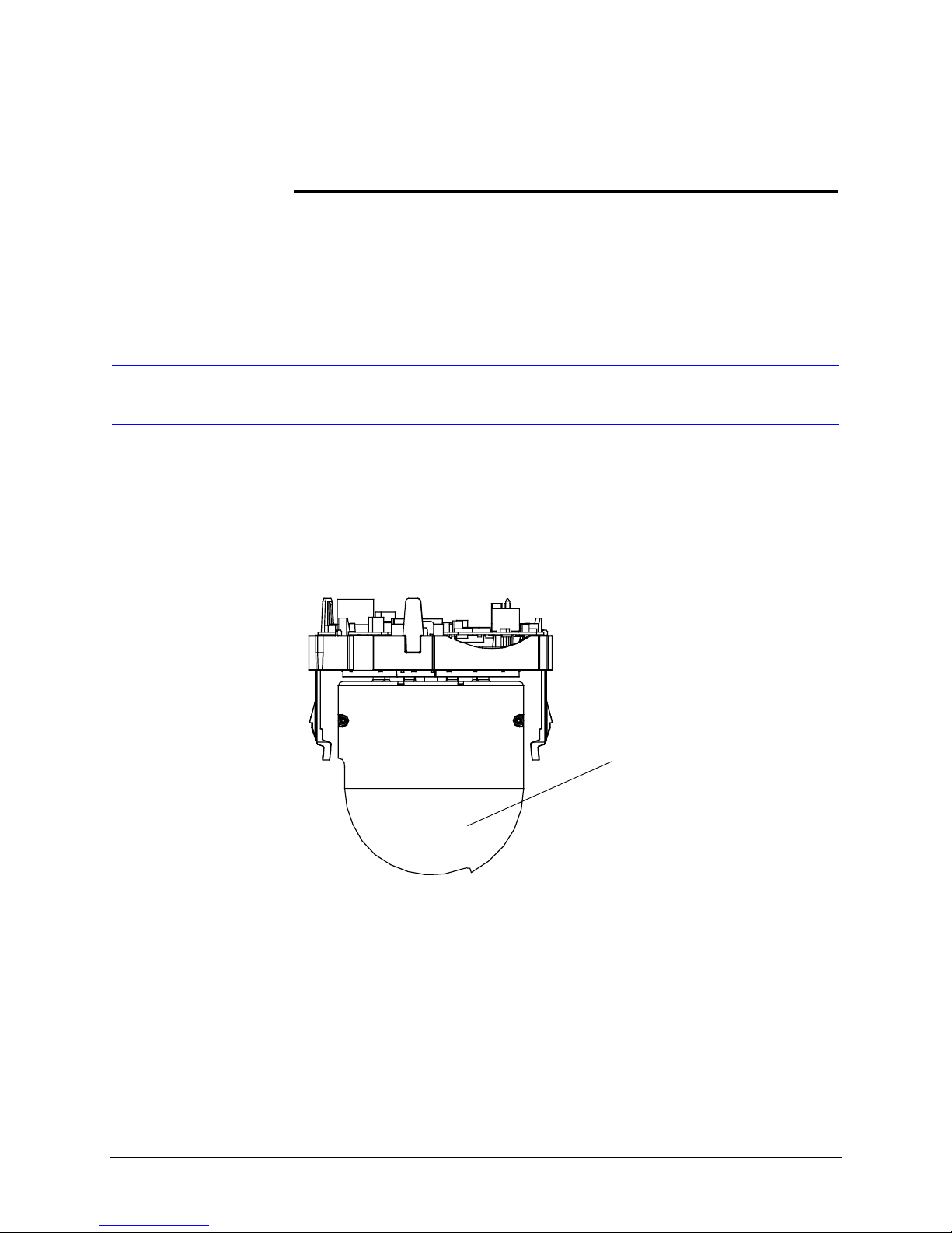
Installing the Pan and Tilt Camera Assembly
1. Set the switches on the printed circuit board as required for your system
configuration. See Chapter 2, Switch Settings.
Figure 1-1 ACUIX Pan and Tilt Camera Assembly
Printed Circuit Board (Set Switches)
Camera
2. Line up the alignment label (yellow label with black dot) below the locking guide in
the housing with the alignment label (yellow label with black dot) on the locking rail
on the pan and tilt camera assembly.
18
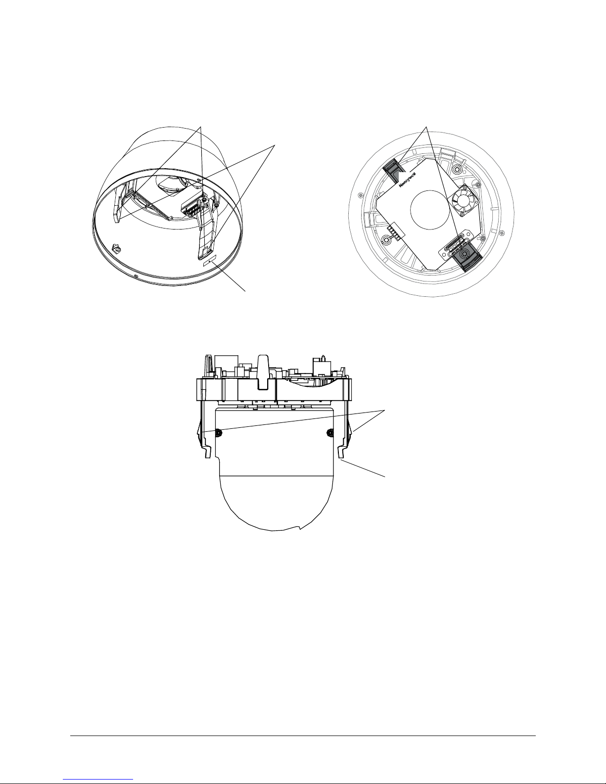
Figure 1-2 ACUIX Housing
ACUIX High Speed Dome User Manual
Locking guide
(2 places)
Locking guide
(2 places)
Ensure the rails on the
pan and tilt assembly
lock into the holes on
the housing guides
Alignment label (yellow
label with black dot)
Figure 1-3 ACUIX Pan and Tilt Camera Assembly Locking Rails
Ensure the 2 rails on the
camera assembly lock
into the holes on the
housing guides
Alignment label
(yellow label with
black dot)
3. Push the camera assembly into the housing until it snaps into place.
Document 800-01023 Rev A 19
02/08
Installing the Pan and Tilt Camera Assembly and Lower Dome
Installing the Lower Dome
Indoor or Outdoor Pendant
1. Hook the lanyard attached to the lower dome on the retaining bracket in the
housing.
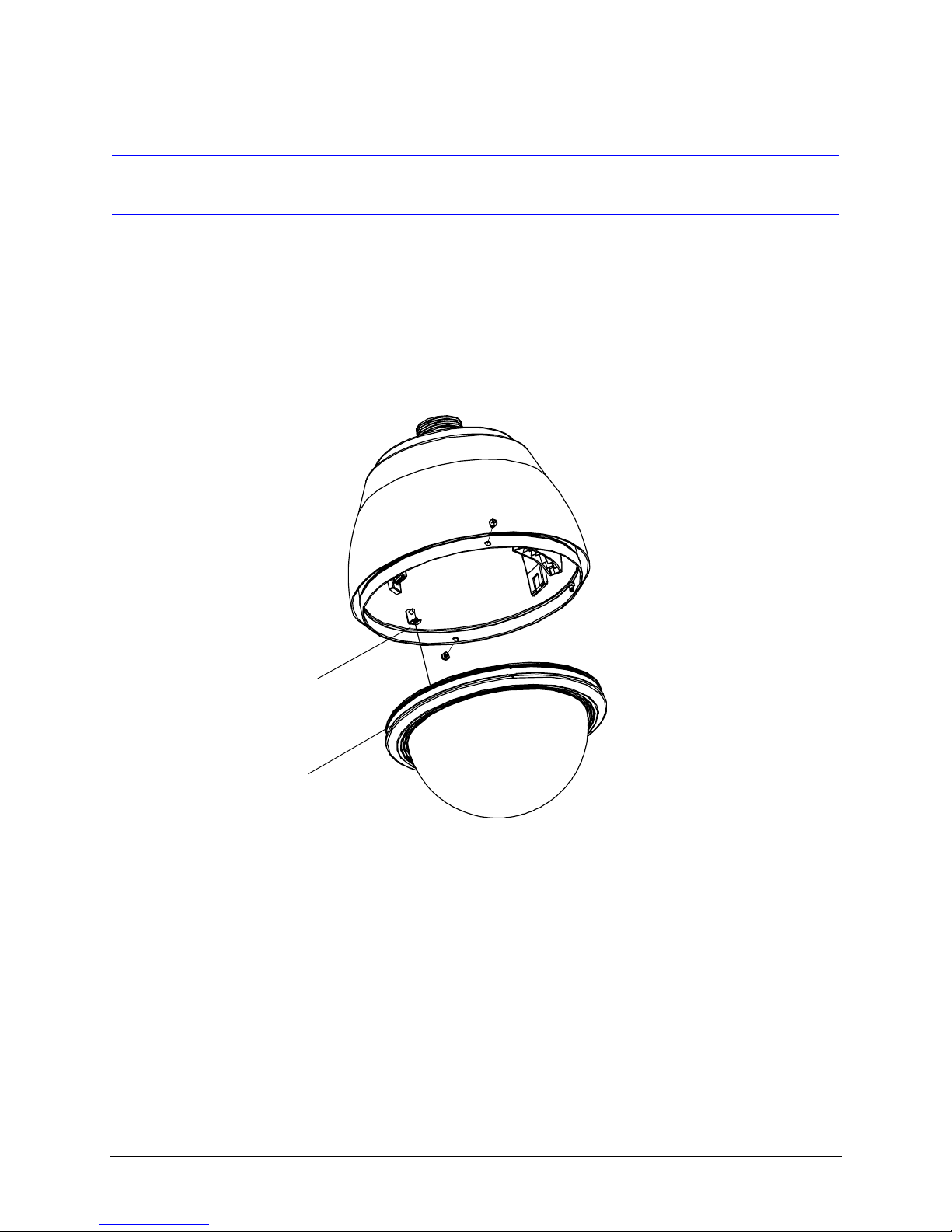
Figure 1-4 Pendant Lower Dome Installation
Hook lanyard from
lower dome to retaining
bracket in housing
Trim ring
2. Ensure the trim ring is in place around the lower dome.
3. Press the lower dome into the housing.
4. Secure the lower dome to the housing by installing the two screws provided with the
lower dome.
20
Switch Settings
The ACUIX has two DIP switches (SW5 and SW6) on the pan and tilt printed circuit board
(PCB) for setting the protocol, baud rate, and parity. These settings must match the
control equipment settings.
There are four rotary switches (SW1, SW2, SW3, and SW4) for setting the ACUIX logical
address for control purposes.
A DIP switch can also be used to restore the default settings and another DIP switch to
override the switch settings for the logical address.
ACUIX High Speed Dome User Manual
2
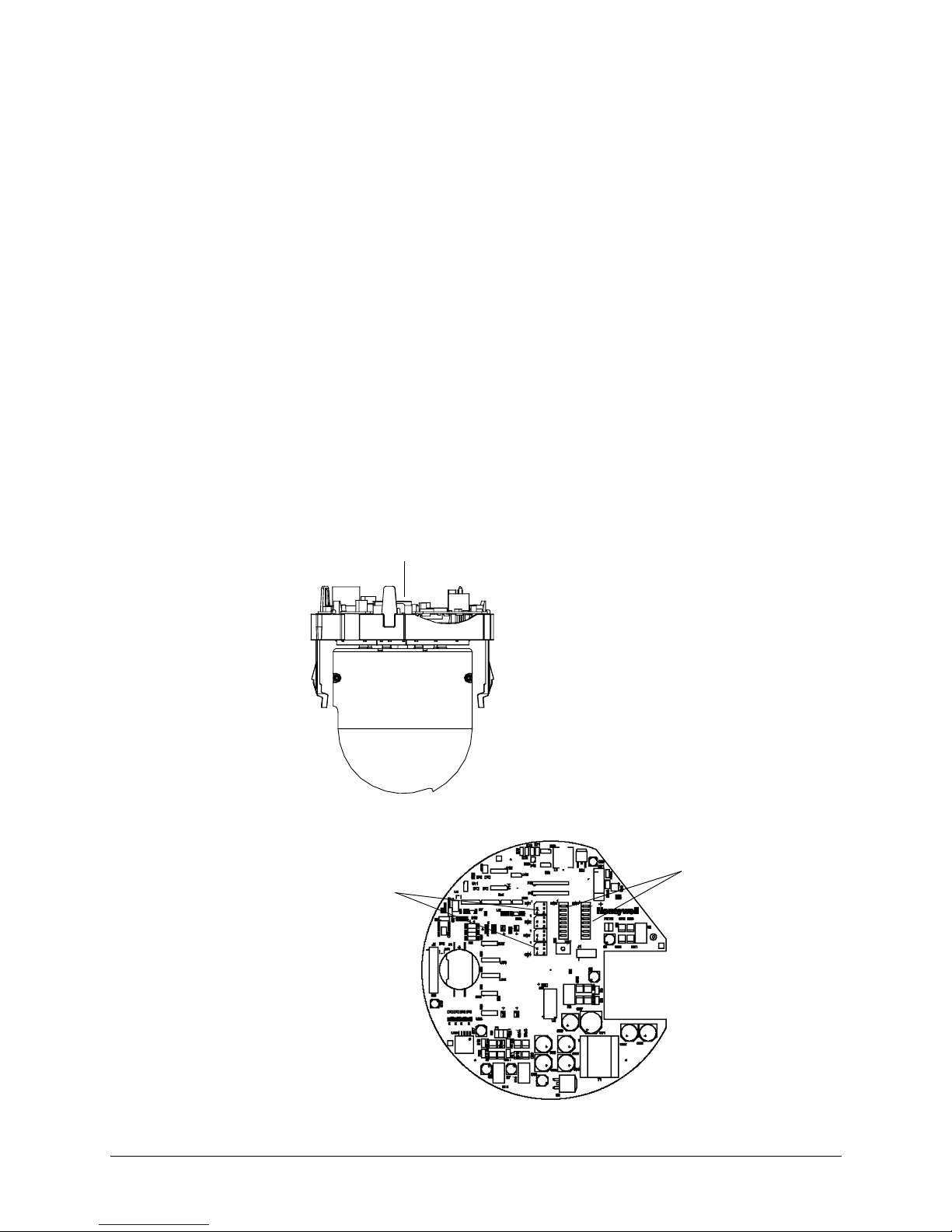
Figure 2-1 ACUIX Pan and Tilt Camera Assembly
Printed circuit board
Figure 2-2 Location of DIP and Rotary Switches on Main Board
Rotary switches
SW1, SW2,
SW3, & SW4
DIP switches
SW5 and SW6
Document 800-01023 Rev A 21
02/08

Switch Settings
Protocol Settings
DIP switch SW5 is used to select the protocol setting for your ACUIX. See Table 2-1 for
more information. The default protocol setting for the ACUIX is the Honeywell Diamond
protocol.
Note If there are invalid settings on SW5 or SW6 regarding protocol or baud rate,
Table 2-1 DIP Switch SW5 ACUIX Protocol Settings
Protocol Name
the system defaults to Diamond protocol at 9600 baud rate.
Switch Position
12345678
IntelliBus™ OFF OFF OFF OFF OFF OFF OFF OFF
Diamond ON OFF OFF OFF OFF OFF OFF OFF
MAXPRO Mode OFF ON OFF OFF OFF OFF OFF OFF
VCL - RS485 ON ON OFF OFF OFF OFF OFF OFF
VCL Video Telemetry
(Control over Coax)
Pelco P ON OFF ON OFF OFF OFF OFF OFF
Pelco D OFF ON ON OFF OFF OFF OFF OFF
OFF OFF ON OFF OFF OFF OFF OFF
22

Baud Rate
ACUIX High Speed Dome User Manual
DIP SW6, position 1 through 4 are used to set the baud rate. The baud rate of the ACUIX
and the control equipment must be the same.
Note If there are invalid settings on SW5 or SW6 regarding protocol or baud rate,
the system defaults to Diamond protocol at 9600 baud rate.
Table 2-2 DIP Switch SW6 ACUIX Baud Rate Settings
Switch Position
Baud Rate
1234
600 OFFOFFOFFOFF
1200 ON OFF OFF OFF
2400 OFF ON OFF OFF
4800 ON ON OFF OFF
9600 OFF OFF ON OFF
19200 ON OFF ON OFF
38400 OFF ON ON OFF
57600 ON ON ON OFF
115200 OFF OFF OFF ON
Document 800-01023 Rev A 23
02/08

Switch Settings
Parity
DIP Switch SW6, positions 5 and 6 are used to set the parity.
Table 2-3 DIP Switch SW6 ACUIX Parity Settings
Switch Position
Parity
None OFF OFF
Even ON OFF
Odd OFF ON
Note SW6, position 7 should be kept OFF. This switch is only used during
development for debugging purposes.
56
Sample Switch Settings
Legend for the following samples:
1 = On/ 0 = Off
Honeywell Diamond
For Honeywell Diamond protocol, the commonly used setting is 9600 baud, even parity.
SW5 - 10000001 (positions 1–8).
In above SW5–8 is ON to force reading from DIP switches. See DIP Switch Address
Override, page 26, for more information on setting SW5–8.
SW6 - 00101000 (positions 1–8) sets the ACUIX to 9600 baud with even parity.
24

VCL - RS485
IntelliBus™
ACUIX High Speed Dome User Manual
For VCL - RS485 protocol, the commonly used setting is 9600 baud, no parity.
SW5 - 11000001 (positions 1–8).
In above SW5–8 is ON to force reading from DIP switches. See DIP Switch Address
Override, page 26, for more information on setting SW5–8.
SW6 - 00100000 (positions 1–8) sets the ACUIX to 9600 baud with no parity.
SW5 - 00000001 (positions 1–8).
In above SW5–8 is ON to force reading from DIP switches. See DIP Switch Address
Override, page 26, for more information on setting SW5–8.
SW6 - 01100000 (positions 1–8) sets the ACUIX to 38400 baud with no parity.
Camera Address Settings
Address selection is via rotary switches SW1, SW2, SW3, and SW4.
Table 2-4 ACUIX Camera Addresses
Address Value
SW1 Units digit
SW2 Tens digit
SW3 Hundreds digit
SW4 Thousands digit
Caution The ACUIX can be addressed from 0000 to 9999. The addressing
scheme may be restricted due to the limitations of the controller
being used to control the ACUIX. For example, the
HEGS5000/HEGS5001 controllers can control camera addresses 1
to 256. The HJZTP can control camera addresses 1 to 128.
Document 800-01023 Rev A 25
02/08

Switch Settings
Address Examples
1. To set the camera address to 1, set SW1 = 1, SW2 = 0, SW3 = 0, SW4 = 0
(CAM - 0001).
2. To set the camera address to 125, set SW1 = 5, SW2 = 2, SW3 = 1, SW4 = 0
(CAM - 0125).
Note If the ACUIX is set to address 0000, it will respond to control commands for
any address. That is, if the ACUIX is set to address 0000 and the operator
sends control commands for address 2, the ACUIX addressed 0000 will
perform the commands for address 2. No validation is performed on the
addresses by the ACUIX.
DIP Switch Address Override
DIP Switch SW5–8 can be set so the ACUIX sets the camera address based on the rotary
switch settings or from memory. SW5–8 should be kept ON during normal operation so that
the logical address can be changed from the on-screen setup menus.
SW5–8
OFF Logical address stored in memory overrides the DIP Switch settings.
ON The ACUIX is forced to read from the rotary switches and overrides the logical
Factory Defaults
The factory default settings are as follows:
Protocol Honeywell Diamond
Baud rate 9600
address stored in memory.
Parity No parity
Address Even
Termination None
26

Restore Factory Defaults
SW5–7 is looked at only when the ACUIX is powered up. If this switch is ON at the time of
power up, the factory defaults will be restored. For an already powered dome, you must
place switch SW5–7 in the ON position, and then cycle the power to the ACUIX for the
factory default settings to be restored.
SW5–7
OFF Normal Operation.
ON Restore Factory Default settings.
Note It is not advisable to keep this DIP switch (SW5–7) in the ON position. Once
ACUIX High Speed Dome User Manual
the factory default is achieved after a single power cycling, place SW5–7
back to the OFF position.
RJ45 Ethernet Connection
The RJ45 connector located on the ACUIX interface board is used for production use and
testing only and has no functionality during normal dome use. This will not damage your
ACUIX dome, but may affect your network. Honeywell recommends you DO NOT connect
your network to the RJ45 connector.
Document 800-01023 Rev A 27
02/08

Switch Settings
28

ACUIX High Speed Dome User Manual
3
Operation and Programming with Honeywell
Diamond Protocol
Introduction
The availability of the ACUIX features and the way the ACUIX features are controlled is
governed by the controller being used and the ACUIX protocol setting. This chapter
describes the operation of the ACUIX set to Honeywell Diamond protocol and controlled
by a model HEGS5000, HEGS5001 or HJZTP joystick controller.
HEGS5000/5001 Controller
Power Up
Upon power up of the ACUIX, a start up
screen displays the protocol, baud rate,
parity, data bits, camera model, and
software (VXWorks and FPGA) release
dates and versions. If the Honeywell
startup screen has been turned off in the
setup menus, an X displays in its place.
---- ACUIX Dome ----
Protocol ........... Diamond
9600 baud no parity -8bits
Camera ............... Model
Honeywell Video Systems
DOMEApp date version B0
FPGABit date version B1
Please wait......_8
Document 800-01023 Rev A 29
02/08
CAM-0006 M

Operation and Programming with Honeywell Diamond Protocol
If the ACUIX is set to find home on startup, the message Finding Home... displays on
the monitor. Once the ACUIX has found home, the message Home Found... is briefly
displayed.
If the ACUIX is not set to find home on startup, the ACUIX finds home when it receives the
first control command. After the ACUIX finds home, the operator can control the ACUIX.
Reset ACUIX
To reset an ACUIX using an HEGS5000/5001 controller you must be logged in as a Master
user on the controller. This reset is the same as if power was removed from the ACUIX and
then restored.
1. Press Dome Menu. Dome Setup Menu displays in the controller’s LCD window. If
Dome Setup Menu is not displayed, press + or - until it displays.
2. Press Enter to access the Dome Setup Menu.
3. Press 4 for Diagnostic Options.
4. Press 7 for Scan and Camera Reset.
Manual Control
You can also press Clear/Manual on the HEGS5000/5001 controller four times to reset the
ACUIX.
Note To restore the ACUIX to factory default settings, you can access the
on-screen setup menus or make use of the DIP switches as described in
Restore Factory Defaults on page 27.
Manual control of an ACUIX dome includes pan, tilt, zoom, focus, and iris. To manually
control an ACUIX, the address of the ACUIX must be selected as the control camera. When
an operator performs a command at the controller, the controller sends out the control
command with the control camera address.
Example: The operator has camera 2 selected as the control camera on the controller. The
operator performs the tilt function on the controller. The controller sends out the tilt
command to camera address 2. All the ACUIX domes on the control loop receive the
command, but only the ACUIX with address 2 performs the tilt command. If the ACUIX is
set to address 0, CAM-0000, the ACUIX responds to commands for all addresses.
When the ACUIX is being manually controlled the letter
M (manual) is added to the camera ID. The camera
message must be turned on in the Display Options
menu for it to be added to the video signal and viewed
on a monitor.
30
CAM-0001 M
 Loading...