

Honeywell acuix es Quick Installation Manual
ACUIX™ ES PTZ Dome Quick Installation Guide
(
)
Pre-installation Cautions
All types of installations must be performed by qualified technical personnel and must be in accordance with all national and local mechanical and electrical codes.
Ensure the mounting surface and installation hardware can hold the combined weight of the scan assembly, housing, lower dome and mount. Any wall or ceiling
mounting of the product should follow the manufacturer’s instructions for the mount used and use best installation practice appropriate for the structure and
material the mount is being attached to.
To prevent damage to the mainboard, follow standard industry precautions for electrostatic discharge sensitive devices.
Cable preparation should be completed prior to the installation. Each dome requires 24V AC at 1 A or 12V DC at 1.5 A. The power supply should be located as
close to the dome as possible for service and electrical isolation purposes.
How to Use this Guide
1. Follow the instructions on pages 2 or 3 for your specific installation type (indoor pendant, surface mount or in-ceiling).
2. Refer to pages 1 and 4 for switch, power and wiring information, which is the same for all installations.
3. Numbered steps have cross references to the insets labeled A through F.
These instructions are only a basic guide. Refer to the ACUIX ES Installation and Configuration Guide for detailed safety and installation information not included here and to configure the domes. Not all models or options are shown and the step order may vary.
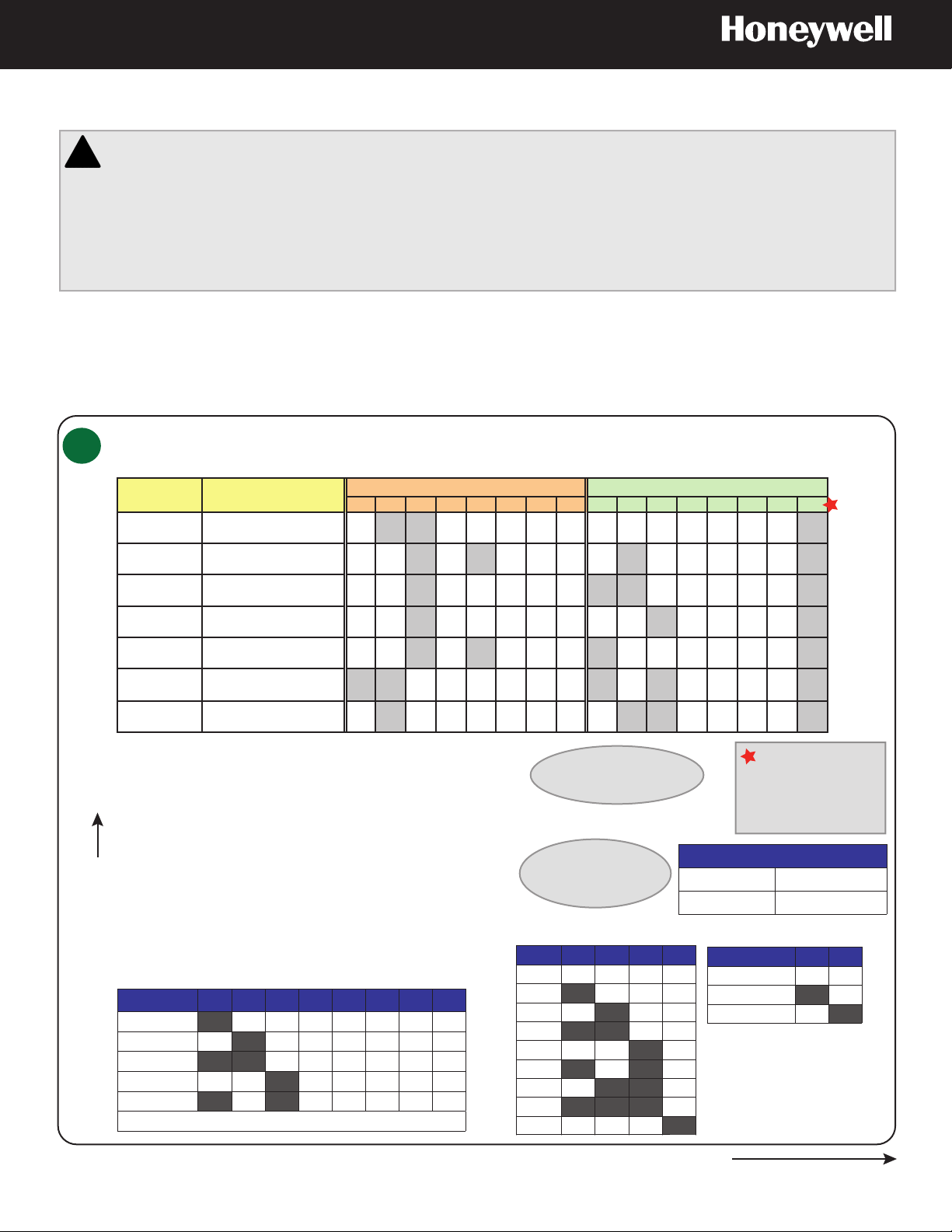
Scan Assembly Mainboard Switches SW2 to SW5
A
Typical SW2 and SW3 Switch Settings (Protocol, Baud and Parity)
Protocol
Baud and Parity
Description
IntelliBus™ 38400 baud, no parity OFF ON ON OFF OFF OFF OFF OFF OFF OFF OFF OFF OFF OFF OFF ON
MAXPRO* 9600 baud, even parity* OFF OFF ON OFF ON OFF OFF OFF OFF ON OFF OFF OFF OFF OFF ON
SW2 - Baud and Parity Settings SW3 – Protocol Setting
1 2 3 4 5 6 7 8 1 2 3 4 5 6 7 8
VCL - RS485** 9600 baud, no parity** OFF OFF ON OFF OFF OFF OFF OFF ON ON OFF OFF OFF OFF OFF ON
VCL UTC 9600 baud, no parity OFF OFF ON OFF OFF OFF OFF OFF OFF OFF ON OFF OFF OFF OFF ON
Diamond 9600 baud, even parity OFF OFF ON OFF ON OFF OFF OFF ON OFF OFF OFF OFF OFF OFF ON
Pelco P 4800 baud, no parity
ON ON OFF OFF OFF OFF OFF OFF ON OFF ON OFF OFF OFF OFF ON
(default for P-type control)
Pelco D 2400 baud, no parity
OFF ON OFF OFF OFF OFF OFF OFF OFF ON ON OFF OFF OFF OFF ON
(default for D-type control)
* NTSC default settings: MAXPRO-mode protocol, 9600 baud, even parity.
** PAL default settings: VCL 485 protocol, 9600 baud, no parity.
SW5 RS485 Termination
NTSC or PAL settings are
based on camera model.
ON
SW5: RS485 Termination
SW5 on
other side
SW4 - Address
SW3 - Protocol
SW2 - Baud/Parity
SW4: Dome Address
Binary Value/Dome
Address
1 (default)
2
3
4
5
See the ACUIX ES Installation and Configuration Guide for a more extensive table.
SW4/1 SW4/2 SW4/3 SW4/4 SW4/5 SW4/6 SW4/7 SW4/8
OFF OFF OFF OFF OFF OFF OFF
ON
OFF
ON ON
OFF OFF
ON
OFF OFF OFF OFF OFF OFF
ON
OFF OFF OFF OFF OFF OFF
OFF OFF OFF OFF OFF
ON
OFF
OFF OFF OFF OFF OFF
ON
SW5 is located on the
opposite side from the
DIP switches.
SW2: Baud Rate and Parity
Baud Rate SW2/1 SW2/2 SW2/3 SW2/4
600 OFF OFF OFF OFF
1200 ON OFF OFF OFF
2400 OFF ON OFF OFF
4800 ON ON OFF OFF
9600
OFF OFF ON OFF
default
19200 ON OFF ON OFF
38400 OFF ON ON OFF
57600 ON ON ON OFF
115200 OFF OFF OFF ON
Switch SW5 RS485 Termination
OFF (default)
ON
Parity SW2/5 SW2/6
None (PAL default)
Even (NTSC default)
Odd
DIP Switch Close Up
For most installations,
leave SW3-8 ON,
otherwise users can
make changes from
the OSD menu.
Not terminated
Terminated in 120 Ohms
OFF OFF
ON OFF
OFF ON
1
Installing the Indoor Pendant or Surface Mount Dome
All ACUIX ES pendant/surface mount shipments include both the skirt and top cap.
Use the part appropriate to the type of installation.
Refer to inset
Indoor Pendant (Using the Top Cap)
Drill the mount holes into the ceiling or wall. Before securing the mount to the
1
B
surface, pull the field wiring through the mount. Make sure the wires extend at
least 12 inches (305 mm) past the end of the ceiling or wall mount threaded
pipe.
Pull the wiring from the mount and through the top cap. Cut the cable length
2
to 6 inches (152 mm). Screw the top cap into the wall or ceiling threaded
pipe. For the wall mount, use the supplied conduit.
Surface Mount (Using the Skirt)
Pull the wires through the skirt wiring access hole and mount the skirt on the
1
B
ceiling.
Finish pulling the field wiring through the skirt. Cut the cable length to 6
2
inches (152 mm).
Both Installations (Pendant and Surface)
A
F
Set the switches on the scan assembly mainboard (SW2, SW3, SW4 and
3
SW5) and the outside of the scan assembly (SW1). Attach the lanyard from
the top cap or skirt to the scan assembly.
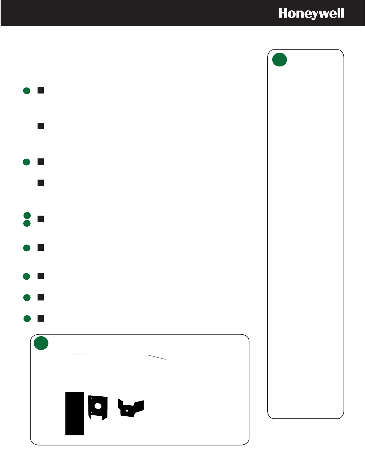
Pendant
C
and Surface
Components
Top Cap
Skirt
Scan Assembly*
* Surface mount with skirt shown
Remove the plugs from the scan assembly, screw the wiring (power, RS485 data,
4
F
contacts) into the holes then put the plugs back. If required, connect the BNC (for
coax).
Secure the scan assembly to the top cap or skirt using 8-32 0.375 Pan Phil
5
C
machine screws.
Align the 3 hooks on the cover with the 3 holes on the inside of the top cap or
6
C
skirt. Rotate the cover until it is secure inside the top cap or skirt.
Align the 2 holes on the lower dome with the 2 screw holes on either side of
7
C
the scan assembly. Secure the lower dome to the scan assembly.
Indoor Pendant
B
Ceiling mount
(HDCM1)
Top cap
Cover
Lower dome
Corner adapter
(HDXCMA1)
Surface Mount
Skirt
Pole mount adapter
(HDXPMA1)
Wiring
access hole
Wall mount
(HDVWM1)
Pendant installed
with a wall mount
Video Switch, Plugs and
BNC Connector
Cover
Lower Dome
Pendant Mounts and Adapters
2
 Loading...