

Honeywell Activ8 PIR, 8IR103 Installation Instructions Manual

PRODUCT DESCRIPTION
Activ8 PIR
Activ8 PIR Activ8 PIR
Activ8 PIR
8IR103
PIR MOTION DETECTOR
With PET IMMUNITY up to 25Kg
INSTALLATION INSTRUCTIONS
English
P/N 7101507 REV. F A.Y.
The Activ8 PIR detector uses a special
designed optical Lens with unique Quad
(Four element) PIR Sensor and new ASIC
based electronics optimized to eliminate false
alarms, caused by small animals and Pets.
The Activ8 PIR provides unprecedented levels
of immunity against visible light.
The Detector offers an exceptional level of
detection capability and stability for every
security installation.
The Activ8 PIR is supplied with Wide Angle
lens.
Activ8 PIR FEATURES DETECTION PATTERN
TYPICAL INSTALLATION
FEATURES
• Quad Linear Imaging Technology for
sharp analysis of body dimensions and
differentiation from background and
animals.
• New ASIC based electronics.
• Immunity to animals up to 25kg (55 lbs).
• 18m Detection Range with Wide Angle
Lens.
• Temperature compensation.
• Compact Design for Residential
Installation.
• Variable pulse width adjustment.
• Sensitivity adjustment.
• Environmental immunity.
• Height installation calibration
free (1.8m – 2.4m).
• LED Remote function.
SELECT MOUNTING LOCATION
Choose a location most likely to intercept an
intruder. See detection pattern. The Quad high
quality sensor detects motion crossing the beam;
it is less sensitive detecting motion towards the
detector.
The Activ8 PIR performs best when provided with
a constant and stable environment.
AVOID THE FOLLOWING LOCATIONS
∗ Facing direct sunlight.
∗ Facing areas subject to rapid
temperature changes.
∗ Areas with air ducts or substantial air
flows.
REMOVAL OF FRONT COVER MOUNTING THE DETECTOR
1. To remove the front cover, unscrew the holding
screw and gently raise the front cover.
2. To remove the PC board, carefully unscrew the
holding screw located on the PC board.
3. Break out the desired holes for proper
installation.
4. The circular and rectangular indentations at the
bottom base are the knockout holes for wire
entry. You may also use mounting holes that are
not in use for running the wiring into the
detector.(For option with bracket - lead wire
through the bracket)
5. Mount the detector base to the wall, corner or
ceiling. (For option with bracket install bracket).
6. Reinstall the PC board by fully tightening the
holding screw. Connect wire to terminal block.
7. Replace the cover by inserting it back in the
appropriate closing pins and screw in the holding
screw.
KNOCKOUT HOLES
DETECTOR INSTALLATION
TERMINAL BLOCK CONNECTIONS
Terminals 1 & 6 - Marked “EOL ” – End of line
option.
Terminals 2 & 3 - Marked “ TAMPER ”
If a Tamper function is required connect these
terminals to a 24-hour normally closed protective
zone in the control unit. If the front cover of the
detector is opened, an immediate alarm signal will
be sent to the control unit.
Terminals 4 & 5 - Marked “ RELAY ”
These are the output relay contacts of the
detector. Connect to a normally closed zone in the
control panel.
Terminal 7 - Marked “ + ” (+12V)
Connect to a positive Voltage output of 8.2 -16Vdc
source (usually from the alarm control unit)
Terminal 8 - Marked “ - ” (GND)
Connect to the negative Voltage output or ground
of the control panel.
PCB LAYOUT
A.
Wire access
holes
B. Use for flat
wall
mounting
C. Corner
mounting use all 4
holes.
Sharp left o
r
right angle
mounting use 2 holes
(top and
bottom)
D. For bracket
mounting
D
B
B
B
B
C C
C C
Unscrew the holding
screw and open base
A
A
A
The Activ8 PIR provides Pet immunity up
to 25Kg (55 lbs). For better immunity
avoid installation in areas where pets can
reach upwards.
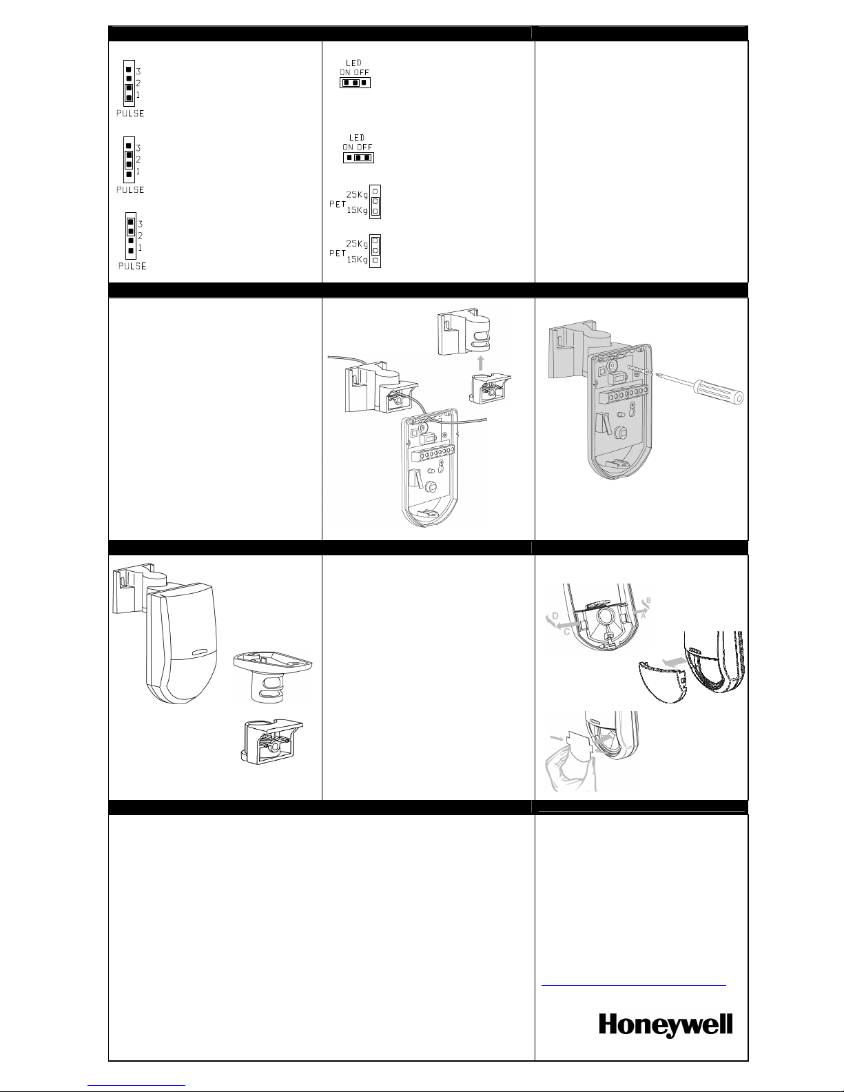
SETTING-UP THE DETECTOR
PULSE WIDTH JUMPER SETTING
LED ENABLE JUMPER SETTING
PET IMMUNITY JUMPER SETTING
PIR SENSITIVITY ADJUSTMENT
POTENTIOMETER– adjustment according to
protected area range.
Use the potentiometer to adjust the detection
range between 68% and 100% (factory set to
84%). Rotate the potentiometer clockwise to
increase range, counter-clockwise to decrease
range.
WIRE SIZE REQUIREMENTS
Use #22 AWG (0.5 mm) or wires with a larger
diameter. Use the following table to determine
required wire gauge (diameter) and length of wire
between the detector and the control panel.
Wire Length m 200 300 400 800
Wire Diameter mm .5 .75 1.0 1.5
Wire Length ft. 800 1200 2000 3400
Wire Gauge # 22 20 18 16
TESTING BRACKET INSTALLATION OPTION
TEST PROCEDURES
WAIT FOR ONE MINUTE OF WARM UP TIME
AFTER APPLYING 12 VDC POWER.
CONDUCT TESTING WITH THE PROTECTED
AREA CLEARED OF ALL PEOPLE.
Walk test
1. Remove front cover.
The pulse jumper must be in position 1. The
LED must be enabled.
2. Replace the front cover.
3. Start walking slowly across the detection zone.
4. Observe that the detector’s LED lights
whenever motion is detected.
5. Allow 5 sec. between each test for the detector
to stabilize.
6. After the walk test is completed, the LED may
be disabled.
NOTE:
Walk tests should be conducted, at least once a
year, to confirm proper operation and coverage of
the detector.
WALL AND CEILING INSTALLATION REPLACING THE LENS
ADDING A FILTER
1. Remove the front cover.
2. Using a small flat screwdriver, press on left
and right snaps of the lens and pull the lens
out from its place (front cover side).
3. Replace a new lens.
4. Push the lens to its place by pressing again
from outside of the front cover until a click is
heard.
5. Replace front cover.
Filter for immunity of 6000 Lux
(Adding the filter may reduce sensitivity by 10%)
TECHNICAL SPECIFICATION
MODEL Activ8 PIR
Detection Method Quad (Four element) PIR
Power Input 9.6 to 16 VDC
Current Draw Standby: 8mA (± 5%)
Active: 10mA (± 5%)
Temperature
Compensation YES
Pulse Width Adjustable
Alarm Period 2 sec (± 0.5sec)
Alarm Output N.C 28VDC 0.1 A with 27Ohm series protection resistor
Tamper Switch N.C 28VDC 0.1A with
10 Ohm series protection resistor - open when cover is removed
Warm Up Period 60sec (± 5sec)
LED Indicator LED is ON during alarm
Operating Temperature -20
°
C to +60°C
(-4°F to +140°F)
RFI Protection 30V/m 10 - 1000MHz
EMI Protection 50,000V of electrical interference from lightning through power line
Dimensions 90mm x 59mm x 37mm
(3.54’’ x 2.32’’ x 1.46’’)
Weight 40gr (1.4oz)
Honeywell Security & Communications
(UK64)Newhouse Industrial Estate
Motherwell
Lanarkshire
ML1 5SB
Tel +44 (0)1698 738200
Fax +44 (0)1698 738300
Tech Support: +44 (0)844 8000 235
intruder/uk/curityse/com.honeywell.www
.
Very stable environment
Jumper #1 = ON
Without PET
Moderate nuisance situation
Jumper #2 = ON
PET up to 15 kg (33.1 lb)
Relatively high chance of false
alarms
Jumper #3 = ON
PET up to 25 kg (55 lb)
LED ON
LED OFF
Immunity to an
animal up to 15 kg
Immunity to an
animal up to 25 kg
In EN 50131-2-2 and PD6662:2010 Grade 2 compliant installations, do not use swivel mount brackets
 Loading...