

Step
Mount
3
Step
Check Signal Strength
2
2C
4C
4C
Connect AC transformer
Plug in the transformer to an available AC source
Check that signal strength is at least 3-5 bars lit
solid at mounting location
Unplug the transformer
Step
Activate Radio
1
Activate radio by using AlarmNet Direct Website at
https://services.alarmnet.com/ or by calling AlarmNet
Technical Support at 800-222-6525, option 1.
A
B
C
D
Signal Strength (RSSI) Function LED Display
Step
Power Up and Program
5
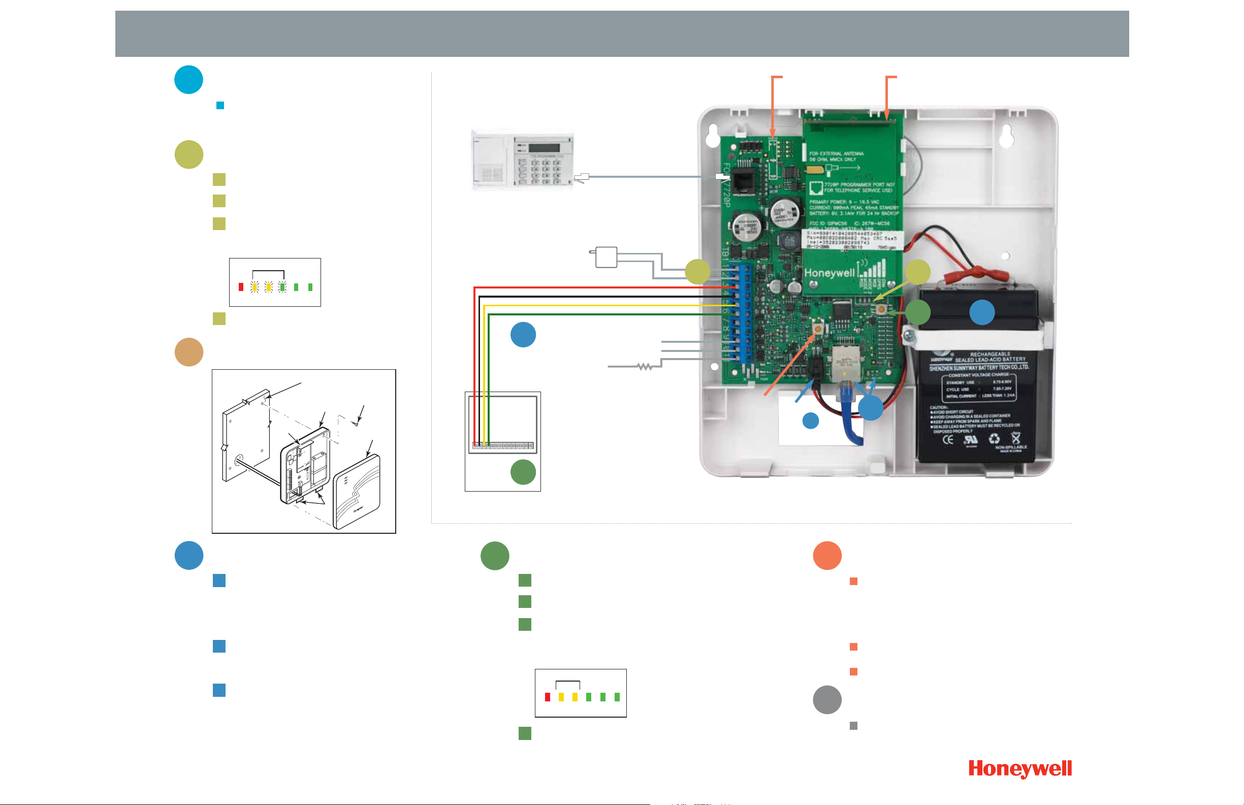
Plug in transformer to a 120V AC source and connect the battery
Power up control panel
Check that module is in ECP mode. Press and hold RSSI/Mode
status switch. Red LED and both Yellow LEDs should be off.
(Refer to Installation and Setup Guide if using any other mode)
Use the web-based programming tool on the AlarmNet Direct
website or the 7720P Programmer to complete programming
(see Installation and Setup Guide for instructions)
Step
Wire
4
Connect control panel wiring
– 12VDC in (red)
– GND (black)
– ECP input (yellow)
– ECP output (green)
7845i-GSM only – Connect to an Ethernet port – the Ethernet
has been detected when the right-most LED is lit in the network
connectivity LCD display
Place the battery inside the case back
– Snap the battery clip onto the right side of the case back and
secure the left side with the screw provided
– After all wiring connections have been made, connect battery
cables to the battery terminals
– Connect battery cable to connector J1
Step
Register
6
The GSM module requires an AlarmNet-i account and may
be registered by one of the following methods:
– Via web-based programming on
https://services.alarmnet.com/alarmnetdirect
– Via 7720P Programmer
– By calling AlarmNet Technical Assistance at 1-800-222-6525
When replacing 7845C series modules, registration may be
done by entering a PIN number
See Installation and Setup Guide for complete instructions
Step
Enable Optional Remote Services*
7
Enable service at https://services.alarmnet.com/alarmnetdirect
Once enabled proceed to https://services.alarmnet.com/totalconnect
7845i-GSM shown at actual size
RSSI/Mode Status Indicator Switch
2A
Zone 6 Input
Zone 7 Input
Fault Output to
Panel Zone Input
Connection for
7720P Programmer
EOLR
AC Transformer
Internal antenna
Tamper
switch
Connector
J1 for
LEDs: Status (green)
Message (yellow)
Fault (red)
L/GSMiSTEP/D
© 2007 Honeywell International Inc.
Quick Set-Up Guide for 7845GSMR Digital Cellular Communicator/7845i-GSM Internet and Digital Cellular Communicator
T
A
B
C
A
B
C
D
4A
4B
5B
5C
Control ECP
Terminals
*Service subscription required
Note: Radio will not display
signal strength until the activation
has been completed. You may
need to power-cycle the radio
to confirm activation.
Min. Lit
ON
INTERNAL
ANTENNA
GYGGRY
WALL OR
MOUNTING
SURFACE
CASE
BACK
MOUNTING
SCREW (4)
(TYP)
CASE
FRON
M1
RSSI
M0
GPRS
IBS
TAB S
OFF
OFF
GYGGRY
 Loading...