

Page 1

Dolphin™ 75e
Preliminary Draft, Not for Release - Please Review 2-3-2015
powered by Android 4.4
User’s Guide
Page 2

Disclaimer
Preliminary Draft, Not for Release - Please Review 2-3-2015
Honeywell International Inc. (“HII”) reserves the right to make changes in specifications and other information contained in this
document without prior notice, and the reader should in all cases consult HII to determine whether any such changes have been
made. The information in this publication does not represent a commitment on the part of HII.
HII shall not be liable for technical or editorial errors or omissions contained herein; nor for incidental or consequential damages
resulting from the furnishing, performance, or use of this material. HII disclaims any and all responsibility and liability for the
selection and use of software and/or hardware to achieve intended results.
This document contains proprietary information that is protected by copyright. All rights are reserved. No part of this document
may be photocopied, reproduced, or translated into another language without the prior written consent of HII.
Web Address: www.honeywellaidc.com
Trademarks
Android, Google, Google Play and other marks are trademarks of Google Inc.
The Bluetooth trademarks are owned by Bluetooth SIG, Inc., U.S.A. and licensed to Honeywell.
Other product names mentioned in this manual may be trademarks or registered trademarks of their respective companies and
are the property of their respective owners.
Patents
For patent information, please refer to www.hsmpats.com.
2015 Honeywell International Inc. All rights reserved.
Page 3

Table of Contents
Preliminary Draft, Not for Release - Please Review 2-3-2015
Chapter 1 - Dolphin 75e Terminal Agency Information
Label Locations....................................................................................................................1-1
Model Number and Serial Number.................................................................................1-1
Approvals by Country...........................................................................................................1-1
FCC Requirements ..............................................................................................................1-2
Dolphin RF Terminal—802.11a/b/g/n/ac, Bluetooth, and/or GSM .................................1-2
Canadian Compliance, Conformité à la règlementation canadienne...................................1-2
RF Exposure Information (SAR) ..........................................................................................1-2
R&TTE Compliance Statement—802.11a/b/g/ac, Bluetooth ...............................................1-3
Honeywell Scanning & Mobility Product Environmental Information....................................1-3
USA, Canada NRTL Safety .................................................................................................1-3
LED Safety...........................................................................................................................1-3
Pacemakers, Hearing Aids and Other Electrically Powered Devices ..................................1-3
Microwaves ..........................................................................................................................1-4
Chapter 2 - Getting Started
Out of the Box ......................................................................................................................2-1
Memory Card Specifications ..........................................................................................2-1
Initial Setup for Dolphin 75e Terminal..................................................................................2-1
Install the Battery ...........................................................................................................2-1
Charge the Battery .........................................................................................................2-2
Power On the Terminal ..................................................................................................2-4
Unlock the Screen..........................................................................................................2-4
Customize the Home Screen and Access Apps ..................................................................2-5
Status Bar ......................................................................................................................2-5
Notification Panel ...........................................................................................................2-6
Common Status and Notification Icons ..........................................................................2-6
Search Bar .....................................................................................................................2-7
Personalize the Home Screen Panels and Favorites Tray ............................................2-7
Apps and Widgets .........................................................................................................2-8
Navigation/Function Buttons ................................................................................................2-8
Hotkeys ..........................................................................................................................2-9
Virtual Keyboard ..................................................................................................................2-9
Using the Virtual Keyboard ............................................................................................2-9
Turning Power On/Off ..........................................................................................................2-9
Suspend Mode.....................................................................................................................2-9
Airplane Mode....................................................................................................................2-10
Replacing the Battery.........................................................................................................2-10
Resetting the Terminal.......................................................................................................2-11
Hard Reset (Cold Boot)................................................................................................2-11
Soft Reset (Warm Boot) ...............................................................................................2-11
Connecting the Terminal to a Computer via a USB Connection........................................2-12
iii
Page 4

File Browser Power Tool ................................................................................................... 2-12
Preliminary Draft, Not for Release - Please Review 2-3-2015
Browser Menu..............................................................................................................2-12
\Honeywell ...................................................................................................................2-12
AutoInstall Settings............................................................................................................2-13
Additional Resources......................................................................................................... 2-13
Chapter 3 - Hardware Overview
Standard Configurations for the Dolphin 75e ...................................................................... 3-1
Peripherals for the Dolphin 75e ........................................................................................... 3-1
Accessories for the Dolphin 75e.......................................................................................... 3-2
Holsters (Model HOLSTER-2 and 6000-HOLSTER)..................................................... 3-2
Wrist Lanyard (Model SL-LANYARD-1).........................................................................3-2
Stylus or Stylus and Tether Kit (Model 70e-Stylus or 70e-STYLUSTHR KIT)............... 3-2
Stylus Battery Door Kits.................................................................................................3-2
Battery (Models 70e-BTSC and 70e-BTEC).................................................................. 3-2
Features of the Dolphin 75e ................................................................................................ 3-3
Front, Bottom, and Right Panels....................................................................................3-3
Back, Top, and Left Panels............................................................................................3-6
Feature Descriptions: Back, Top, and Left Panels ........................................................ 3-7
The I/O Connector ...............................................................................................................3-8
Battery .................................................................................................................................3-8
Replacement Battery Specifications .............................................................................. 3-8
Charging Options...........................................................................................................3-9
Charging Time ...............................................................................................................3-9
Important Charging Guidelines.................................................................................... 3-10
Managing Battery Power ............................................................................................. 3-10
Storing Batteries .......................................................................................................... 3-11
Guidelines for Battery Pack Use and Disposal ............................................................ 3-11
System Resets .................................................................................................................. 3-12
Hardware Maintenance ..................................................................................................... 3-12
Installing a Memory Card................................................................................................... 3-12
Installation and/or Replacement ..................................................................................3-12
Chapter 4 - Using the Scan Image Engine
Overview.............................................................................................................................. 4-1
LED Safety .......................................................................................................................... 4-1
Image Engine Specifications ............................................................................................... 4-1
Field of View .................................................................................................................. 4-1
Depth of Field ................................................................................................................ 4-1
Supported Bar Code Symbologies ............................................................................... 4-2
Decoding ............................................................................................................................. 4-2
Using the Scan Demo to Decode a Bar Code ...............................................................4-2
Automatic Scanning....................................................................................................... 4-3
Continuous Scanning.....................................................................................................4-3
Configuring the Scan Demo Application........................................................................ 4-4
Using the ScanTool Power Tool ....................................................................................4-5
Aiming Beam ................................................................................................................. 4-6
iv
Page 5

Capturing Images ................................................................................................................4-6
Preliminary Draft, Not for Release - Please Review 2-3-2015
Taking an Image with the Imaging Demo ......................................................................4-6
Using the IQ Image Demo to decode intelligent bar codes and capture images........... 4-7
Using the Signature Demo.............................................................................................4-8
Uploading Images................................................................................................................4-8
Chapter 5 - Using the Color Camera
Overview.............................................................................................................................. 5-1
Opening the Camera app and Adjusting the Settings ......................................................... 5-1
Adjusting the Camera/Video Settings.................................................................................. 5-1
Taking a Picture................................................................................................................... 5-1
Taking a Panoramic Picture ................................................................................................ 5-2
Uploading Pictures and Videos ........................................................................................... 5-2
Chapter 6 - Settings
Overview.............................................................................................................................. 6-1
Wireless & Network Settings ............................................................................................... 6-1
Device Settings.................................................................................................................... 6-1
Sound Settings .............................................................................................................. 6-1
Display Settings............................................................................................................. 6-1
Honeywell Smart Sensors Settings ............................................................................... 6-2
Storage Settings ............................................................................................................ 6-2
Battery Settings ............................................................................................................. 6-2
Apps Settings.................................................................................................................6-2
Managing Apps.............................................................................................................. 6-3
Personal Settings ................................................................................................................ 6-4
Accounts & sync ............................................................................................................6-4
Security.......................................................................................................................... 6-4
Language & input ................................................................................................................6-6
Language....................................................................................................................... 6-6
Spelling Correction ........................................................................................................ 6-6
Personal Dictionary........................................................................................................6-6
Keyboard & Input Methods ............................................................................................ 6-6
Backup & reset .............................................................................................................. 6-7
System................................................................................................................................. 6-7
Date & Time...................................................................................................................6-7
Accessibility ...................................................................................................................6-7
Developer options.......................................................................................................... 6-7
About Phone.................................................................................................................. 6-7
Chapter 7 - Communication
Wireless & Networks Settings ............................................................................................. 7-1
Connecting the Terminal to a Wireless Network .................................................................7-1
v
Page 6

Wi-Fi Network Connections ................................................................................................. 7-2
Preliminary Draft, Not for Release - Please Review 2-3-2015
Turning Wi-Fi Networking On or Off .............................................................................. 7-2
Connecting to a Wi-Fi Network...................................................................................... 7-2
Receiving Network Notifications ....................................................................................7-2
Adding a Wi-Fi Network ................................................................................................. 7-2
Advanced Wi-Fi Settings and Network Utilities ................................................................... 7-2
Advanced Wi-Fi Menu ................................................................................................... 7-2
Wi-Fi Radio Settings Power Tool......................................................................................... 7-3
Wireless Manager Power Tool ............................................................................................ 7-3
Airplane Mode ..................................................................................................................... 7-4
Virtual Private Networks (VPN) ........................................................................................... 7-4
Adding a VPN ................................................................................................................ 7-4
Connecting to a VPN .....................................................................................................7-4
Disconnecting from a VPN.............................................................................................7-5
Ethernet Communication ..................................................................................................... 7-5
Chapter 8 - Working with Bluetooth and NFC Technology
Bluetooth Technology..........................................................................................................8-1
Turning the Bluetooth Radio On or Off ..........................................................................8-1
Pairing and Trusted Devices..........................................................................................8-1
Connecting to Other Bluetooth Devices......................................................................... 8-1
Configuring or Unpairing Bluetooth Devices.................................................................. 8-1
Making the Terminal Discoverable ................................................................................ 8-1
Bluetooth Menu Options ................................................................................................8-2
Sharing Pictures and Video ...........................................................................................8-2
Near Field Communication (NFC) Technology.................................................................... 8-3
Hardware Requirements................................................................................................ 8-3
Security Recommendation.............................................................................................8-3
NFC Settings ................................................................................................................. 8-3
Reading NFC Tags ........................................................................................................ 8-4
Transferring screen content via NFC............................................................................. 8-4
Using the NFC Demos................................................................................................... 8-4
Chapter 9 - Dolphin 70e Black HomeBase (Model 70e-HB)
Overview.............................................................................................................................. 9-1
Unpacking the HomeBase...................................................................................................9-1
Optional Equipment ....................................................................................................... 9-1
Charging Overview .............................................................................................................. 9-1
Communications..................................................................................................................9-1
Convenient Storage.............................................................................................................9-1
Capacity............................................................................................................................... 9-2
Dimensions..........................................................................................................................9-2
Weight ................................................................................................................................. 9-2
Parts and Functions.............................................................................................................9-3
Front Panel ................................................................................................................... 9-3
Back Panel ......................................................................................................................... 9-4
Bottom Panel ....................................................................................................................... 9-4
vi
Page 7

Power .................................................................................................................................. 9-4
Preliminary Draft, Not for Release - Please Review 2-3-2015
Connecting Power to the HomeBase .................................................................................. 9-5
Charging the Main Battery................................................................................................... 9-5
Charging a Spare Battery in the Auxiliary Battery Well ....................................................... 9-5
Communication....................................................................................................................9-6
Requirements ................................................................................................................ 9-6
Setting Up and Connecting the Dolphin Terminal to the HomeBase............................. 9-6
Mounting the HomeBase ..................................................................................................... 9-6
Optional DIN Rail Mount................................................................................................ 9-6
Additional Hardware ...................................................................................................... 9-6
Installing the DIN Rail ....................................................................................................9-7
Chapter 10 - Dolphin 70e Black eBase (Model 70e-EHB)
Overview............................................................................................................................ 10-1
Unpacking the eBase ........................................................................................................ 10-1
Optional Equipment ..................................................................................................... 10-1
Charging Overview ............................................................................................................ 10-1
Convenient Storage........................................................................................................... 10-1
Capacity............................................................................................................................. 10-2
Dimensions........................................................................................................................ 10-2
Weight ............................................................................................................................... 10-2
Parts and Functions........................................................................................................... 10-3
Front Panel .................................................................................................................. 10-3
Back Panel ....................................................................................................................... 10-4
Bottom Panel ..................................................................................................................... 10-5
Power ................................................................................................................................ 10-5
Connecting Power to the eBase ........................................................................................ 10-5
Charging the Main Battery................................................................................................. 10-5
To Power a Terminal and Charge its Main Battery............................................................ 10-5
Charging a Spare Battery in the Auxiliary Battery Well .................................................... 10-6
Communication..................................................................................................................10-6
Establishing Ethernet Communication......................................................................... 10-6
Establishing USB Communication............................................................................... 10-7
Mounting the eBase........................................................................................................... 10-8
Chapter 11 - Dolphin 70e Black Mobile Base (Model 70e-MB)
Overview............................................................................................................................ 11-1
Charging Overview ............................................................................................................ 11-1
Convenient Storage........................................................................................................... 11-1
Dimensions........................................................................................................................ 11-1
Weight ............................................................................................................................... 11-1
Mobile Base Components ................................................................................................ 11-2
Adjustable Arm with Suction Cup Base for Windshield Mounting ..................................... 11-2
Mounting the Mobile Base ................................................................................................. 11-3
Safety Precautions.......................................................................................................11-3
Installation.................................................................................................................... 11-3
vii
Page 8

Charging the Main Battery................................................................................................. 11-4
Preliminary Draft, Not for Release - Please Review 2-3-2015
To Power a Terminal and Charge its Main Battery...................................................... 11-5
Removing the Cable .......................................................................................................... 11-6
Chapter 12 - Dolphin 70e Black ChargeBase (Model 70e-CB)
Overview............................................................................................................................ 12-1
Unpacking the ChargeBase............................................................................................... 12-1
Charging Overview ............................................................................................................ 12-1
Convenient Storage........................................................................................................... 12-1
Capacity............................................................................................................................. 12-1
Dimensions........................................................................................................................ 12-2
Weight ............................................................................................................................... 12-2
Parts and Functions........................................................................................................... 12-2
Front Panel .................................................................................................................. 12-2
Dock LEDs................................................................................................................... 12-2
Back Panel ........................................................................................................................ 12-3
Power Supply Connector ............................................................................................. 12-3
Bottom Panel ..................................................................................................................... 12-3
Power ................................................................................................................................ 12-3
Connecting Power to the ChargeBase ....................................................................... 12-4
Charging the Main Battery........................................................................................... 12-4
To Power a Terminal and Charge its Main Battery...................................................... 12-4
Mounting the ChargeBase.................................................................................................12-4
Optional DIN Rail Mount.............................................................................................. 12-5
Additional Hardware .................................................................................................... 12-5
Installing the DIN Rail ..................................................................................................12-5
Chapter 13 - Dolphin 70e Black Net Base (Model 70e-NB)
Unpacking the Net Base.................................................................................................... 13-1
Optional Equipment ..................................................................................................... 13-1
Charging Overview ............................................................................................................ 13-1
Convenient Storage........................................................................................................... 13-1
Capacity............................................................................................................................. 13-1
Dimensions........................................................................................................................ 13-2
Weight ............................................................................................................................... 13-2
Parts and Functions........................................................................................................... 13-2
Front Panel .................................................................................................................. 13-2
Bottom Panel ..................................................................................................................... 13-4
Power ................................................................................................................................ 13-4
Connecting Power to the Net Base..............................................................................13-4
Charging the Main Battery........................................................................................... 13-4
To Power a Terminal and Charge the Main Battery .................................................... 13-4
viii
Page 9

Communication..................................................................................................................13-5
Preliminary Draft, Not for Release - Please Review 2-3-2015
Establishing Ethernet Communication......................................................................... 13-5
Bottom Panel ............................................................................................................... 13-6
Optional DIN Rail Mount.............................................................................................. 13-6
Additional Hardware .................................................................................................... 13-6
Installing the DIN Rail ..................................................................................................13-7
Chapter 14 - Customer Support
Product Service and Repair............................................................................................... 14-1
Technical Assistance.........................................................................................................14-1
Warranty Disclaimer: Proper Use of a Touch Screen Mobile Device ................................ 14-1
Limited Warranty ............................................................................................................... 14-1
How to Extend Your Warranty ........................................................................................... 14-2
ix
Page 10

x
Preliminary Draft, Not for Release - Please Review 2-3-2015
Page 11
1
!
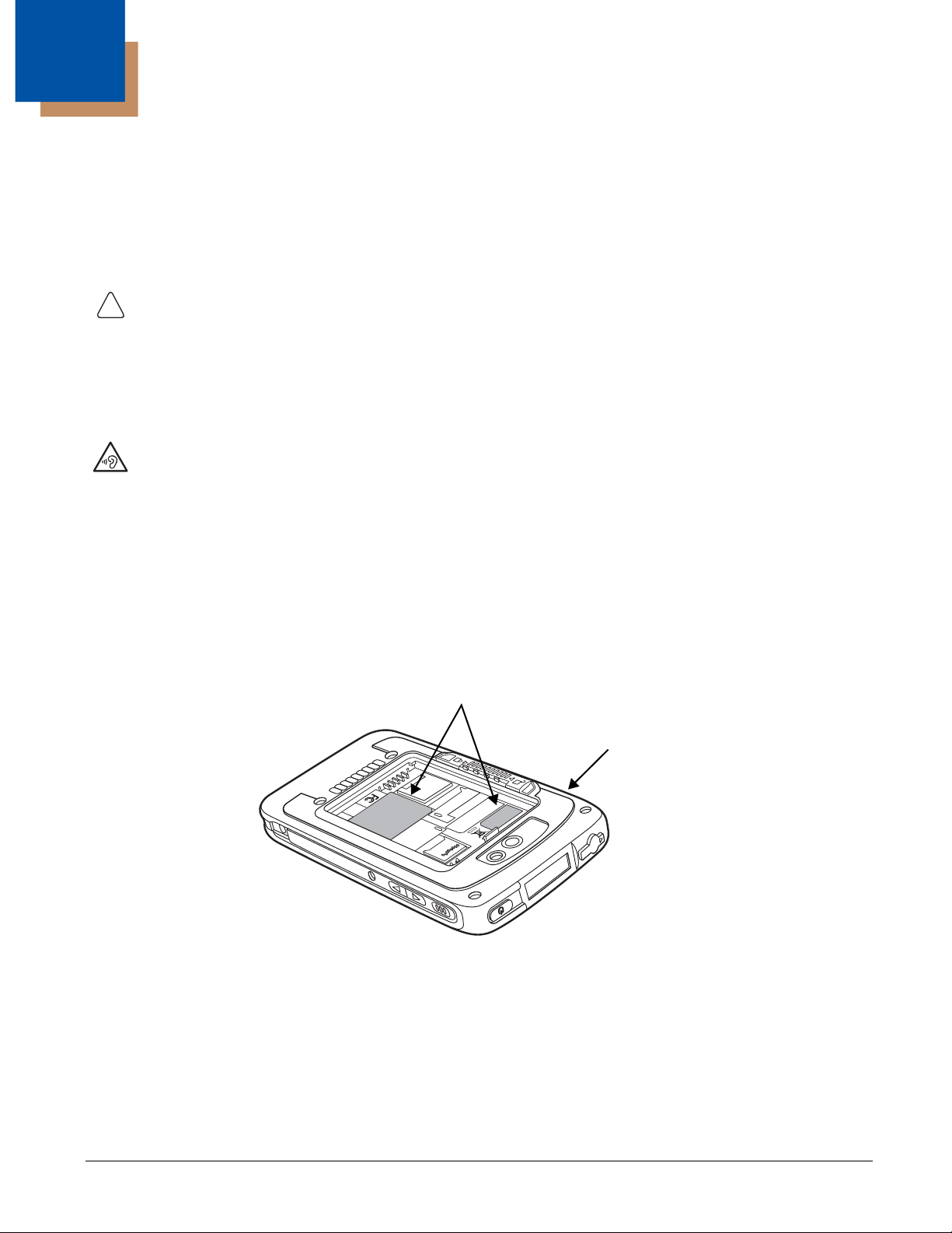
Back Panel of the terminal with the battery door
and battery removed.
Compliance Labels and Marks
Preliminary Draft, Not for Release - Please Review 2-3-2015
Dolphin 75e Terminal Agency Information
Dolphin 75e handheld computers meet or exceed the requirements of all applicable standards organizations for safe operation.
However, as with any electrical equipment, the best way to ensure safe operation is to operate them according to the agency
guidelines that follow. Read these guidelines carefully before using your Dolphin terminal.
This documentation is relevant for the following Dolphin models: 75eL00 and 75eL0N.
Caution: Read the Guidelines for Battery Pack Use and Disposal on page 3-16 and all cautionary markings on the
battery, charging peripheral, or device using the battery before attempting to install, use, or charge the battery. Risk
of fire and burns if improperly handled. Do not open, crush, heat above 60°C (140°F), or incinerate.
Caution: Any changes or modifications not expressly approved by the grantee of this device could void the user’s
authority to operate the equipment.
Mise en
garde:
Warning: To prevent possible hearing damage, do not listen at high volume levels for long periods.
For body worn operation, this device has been tested and meets the limits regarding human exposure to electromagnetic
radiation set forth in related FCC, IC and EC rules, guidelines and standards for use with the following body worn accessories:
HOLSTER-2 and 6000-HOLSTER. Use of other accessories may not ensure compliance with the mentioned rules.
Fonctionnement près du corps:
ce dispositif a été testé et s'avère conforme aux règles et lignes directrices des normes FCC, IC et EC, relatives aux limites
d'une exposition humaine sécuritaire au rayonnement électromagnétique pour une utilisation près du corps des accessoires
suivants: HOLSTER-2 et 6000-HOLSTER.
L'utilisation d'autres accessoires peut ne pas assurer la conformité avec les règles mentionnées.
Tout changement ou modification non expressément approuvées par le bénéficiaire de cet appareil peut annuler
l'autorisation d'utiliser l'équipement.
Label Locations
Model Number and Serial Number
The model (item) number and serial number for the terminal are located on labels affixed to the bottom of the battery well.
Approvals by Country
Refer to the Honeywell Scanning & Mobility compliance center at www.honeywellaidc.com/compliance to review and download
any publicly available documentation pertaining to the certification of this product in a given country.
1 - 1
Page 12

FCC Requirements
Preliminary Draft, Not for Release - Please Review 2-3-2015
Dolphin RF Terminal—802.11a/b/g/n/ac, Bluetooth, and/or GSM
This device complies with Part 15 of the FCC Rules. Operation is subject to the following two conditions:
1. This device may not cause harmful interference.
2. This device must accept any interference received, including interference that may cause undesired operation.
This equipment has been tested and found to comply with the limits for a Class B digital device pursuant to Part 15 of the
FCC Rules. These limits are designed to provide reasonable protection against harmful interference in a residential
installation. This equipment generates, uses, and can radiate radio frequency energy and, if not installed and used in
accordance with the instructions, may cause harmful interference to radio communications. However, there is no guarantee
that interference will not occur in a particular installation. If this equipment does cause harmful interference to radio or
television reception, which can be determined by turning the equipment off and on, the user is encouraged to try to correct
the interference by one or more of the following measures:
• Reorient or relocate the receiving antenna.
• Increase the separation between the equipment and receiver.
• Connect the equipment into an outlet on a circuit different from that to which the receiver is connected.
• Consult the dealer or an experienced radio/TV technician for help.
If necessary, the user should consult the dealer or an experienced radio/television technician for additional suggestions.
The user may find the following booklet helpful: “Something About Interference.” This is available at FCC local regional
offices. Our company is not responsible for any radio or television interference caused by unauthorized modifications of this
equipment or the substitution or attachment of connecting cables and equipment other than those specified by our
company. The correction is the responsibility of the user. Use only shielded data cables with this system.
Canadian Compliance, Conformité à la règlementation canadienne
This device complies with Industry Canada license-exempt RSS standard(s). Operation is subject to the following two
conditions:
1. This device may not cause harmful interference.
2. This device must accept any interference received, including interference that may cause undesired operation.
5GHz band: Sub-band 5.150 - 5.250 GHz of the 5GHz LE-LAN (License Exempt Local Area Network Devices) supported in this
device is permitted for indoor operation only.
Cet appareil est conforme aux normes RSS avec exemption de licence d'Industrie Canada. Son fonctionnement est assujetti
aux conditions suivantes:
1. Cet appareil ne doit pas causer de brouillage préjudiciable.
2. Cet appareil doit pouvoir accepter tout brouillage reçu, y compris le brouillage pouvant causer un fonctionnement
indésirable.
Bande 5 Ghz: La bande inferieure de 5,150 à 5,250 GHz de la 5GHz LE-LAN (License Exempt Local Area Network Devices)
pris en charge dans ce dispositif est autorisée pour une utilisation en intérieur uniquement.
RF Exposure Information (SAR)
This device meets the government's requirements for exposure to radio waves. This device is designed and manufactured not to
exceed the emission limits for exposure to radio frequency (RF) energy set by the Federal Communications Commission of the
U.S. Gover nment.
The exposure standard for wireless devices employs a unit of measurement known as the Specific Absorption Rate, or SAR.
The SAR limit set by the FCC is 1.6W/Kg and for Europe 2W/Kg. Although the SAR is determined at the highest certified power
level, the actual SAR level of the device while operating can be well below the maximum value. This is because the device is
designed to operate at multiple power levels so as to use only the poser required to reach the network. In general, the closer you
are to a wireless base station antenna, the lower the power output.
1 - 2
Page 13

The highest reported SAR values for head, body-worn accessory and simultaneous transmission use conditions are: ____ W/kg
!
Preliminary Draft, Not for Release - Please Review 2-3-2015
(____ g), ____ W/kg (____ g) and ____ W/kg (____ g).
The highest reported CE SAR values for head, body-worn accessory and simultaneous transmission use conditions are: ____
W/kg (____ g), ____ W/kg ( ____ g), ____ W/kg ( ____ g).
While there may be differences between the SAR levels of various devices and at various positions, they all meet the
government requirement.
The FCC has granted an Equipment Authorization for this device with all reported SAR levels evaluated as in compliance with
the FCC RF exposure guidelines. SAR information on this device is on file with the FCC and can be found under the Display
Grant section of www.fcc.gov/oet/ea/fccid after searching on FCC ID: HD5-75EL00 and HD5-75EL0N.
R&TTE Compliance Statement—802.11a/b/g/ac, Bluetooth
The CE marking indicates compliance with the following directives:
• 1995/5/EC R&TTE
• 2011/65/EU RoHS (Recast)
In addition, this product complies to 2006/95/EC Low Voltage Directive when supplied with the recommended power supply.
European Contact:
Hand Held Products Europe B.V.
Nijverheidsweg 9-13
5627 BT Eindhoven
The Netherlands
Honeywell shall not be liable for use of our product with equipment (i.e., power supplies, personal computers, etc.) that is not CE
marked and does not comply with the Low Voltage Directive.
The equipment is intended for use throughout the European Community; PAN European Frequency Range: 2.400–2.4835 GHz.
Operating Frequency Ranges:
• 2400 - 2483.5 MHz, Wideband Data Transmission Systems (WLAN IEEE 802.11 b,g,n at 2.4 GHz);
• 5150 - 5350 MHz and 5470 - 5725 MHz, Wideband Data Transmission Systems (WLAN/RLAN IEEE 802.11 a,n,ac at 5 GHz);
• Operation on sub-band 5150 - 5350 MHz is permitted indoor only.
Honeywell Scanning & Mobility Product Environmental Information
Refer to www.honeywellaidc.com/environmental for the RoHS / REACH / WEEE information.
USA, Canada NRTL Safety
UL and C-UL listed: UL60950-1 2nd Edition, and CSA C22.2 No. 60950-1-07 2nd Edition.
LED Safety
LEDs have been tested and classified as “EXEMPT RISK GROUP” to the Standard: IEC 62471:2006.
Caution! Do not view directly with optical instruments.
Pacemakers, Hearing Aids and Other Electrically Powered Devices
Most manufacturers of medical devices adhere to the IEC 601-1-2 standard. This standard requires devices to operate properly
in an EM Field with a strength of 3V/m over a frequency range of 26 to 1000MHz. The maximum allowable field strength emitted
by the Dolphin terminal is 0.3V/m according to Subpart B of Part 1 of the FCC rules. Therefore, the RF from the Dolphin terminal
has no effect on medical devices that meet the IEC specification.
1 - 3
Page 14

Microwaves
Preliminary Draft, Not for Release - Please Review 2-3-2015
The radio in the Dolphin RF terminal operates on the same frequency band as a microwave oven. Therefore, if you use a
microwave within range of the Dolphin RF terminal you may notice performance degradation in your wireless network. However,
both your microwave and your wireless network will continue to function.
1 - 4
Page 15
2
!
2
1
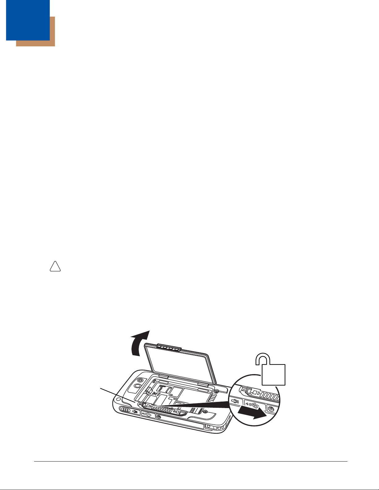
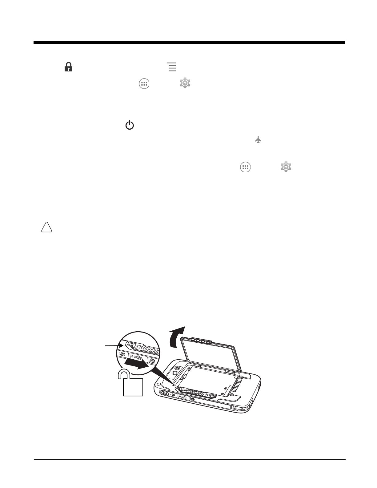
Battery Door Lock
Preliminary Draft, Not for Release - Please Review 2-3-2015
Getting Started
Out of the Box
Verify that the carton contains the following items:
• Dolphin 75e handheld computer (terminal)
• 1 GB, 2 GB or 4 GB microSD™ Memory Card (Optional)
• 3.7V Li-ion rechargeable battery
• USB charge/communication cable
• Power adapter with regional plug adapters
• Quick start guide
• Compliance regulatory sheet
If you ordered accessories for your terminals, verify that they are also included with the order. Be sure to keep the original
packaging in the event that the Dolphin terminal should need to be returned for service.
Memory Card Specifications
Honeywell recommends the use of Single Level Cell (SLC) industrial grade microSD or microSDHC™ memory cards with
Dolphin terminals for maximum performance and durability. Contact a Honeywell sales representative for additional
information on qualified memory card options.
Initial Setup for Dolphin 75e Terminal
Install the Battery
Before installing the main battery, read the Guidelines for Battery Pack Use and Disposal on page 3-11.
The terminal is shipped with the battery packaged separate from the unit. To install the battery, follow the installation steps
illustrated. For information on how to remove the battery, see Replacing the Battery on page 2-10.
Ensure all components are dry prior to placing the battery in the terminal. Mating wet components may cause
damage not covered by the warranty.
We recommend use of Honeywell Li-ion battery packs. Use of any non-Honeywell battery may result in damage
not covered by the warranty.
Important: All battery and connector doors must be present, undamaged, and properly closed to maintain the
environmental rating of the terminal.
Note: Standard battery and standard battery door shown.
2 - 1
Page 16

Charge the Battery
3
4
5
6
Apply pressure to the edges of the
battery door before engaging the lock to
ensure the door is properly closed.
!
!
Preliminary Draft, Not for Release - Please Review 2-3-2015
The power source for the Dolphin terminal is the 3.7V Li-ion rechargeable battery located under the battery door on the
back panel of the device. See Battery on page 3-8 for additional information on battery storage, use, and disposal.
Important: Removing the battery from the terminal erases all non-persistent memory. Always place the terminal in Suspend
mode before removing the battery. For information on how to remove the battery from the terminal, see
Replacing the Battery on page 2-10.
Before Initial Use
Dolphin terminals ship with the battery significantly discharged of power. After installing the battery in the terminal, charge
the battery with a Dolphin 75e compatible charging peripheral for a minimum of 4 hours for the standard battery pack or 6
hours for the extended battery pack. When using the 70e-USB Charge/Communication cable to charge from a 500mA
USB port on a host device, charge the battery for a minimum of 6 hours for the standard battery and 8 hours for the
extended battery.
Note: Inadequate source current may interfere with effective battery charging; see Important Charging Guidelines on page
3-10 for additional information.
We recommend use of Honeywell peripherals, power cables, and power adapters. Use of any non-Honeywell
peripherals, cables, or power adapters may cause damage not covered by the warranty.
Dolphin 75e model terminals are designed for use with the following charging devices and cables: 70e-HB, 70e-CB,
70e-EHB, 70e-NB, 70e-MB, 70e-MC, and 70e-USB ADAPTERKIT. See pages 3-1 and 3-2 for additional information on
peripherals and accessories.
Ensure all components are dry prior to mating terminals/batteries with peripheral devices. Mating wet
components may cause damage not covered by the warranty.
2 - 2
Page 17
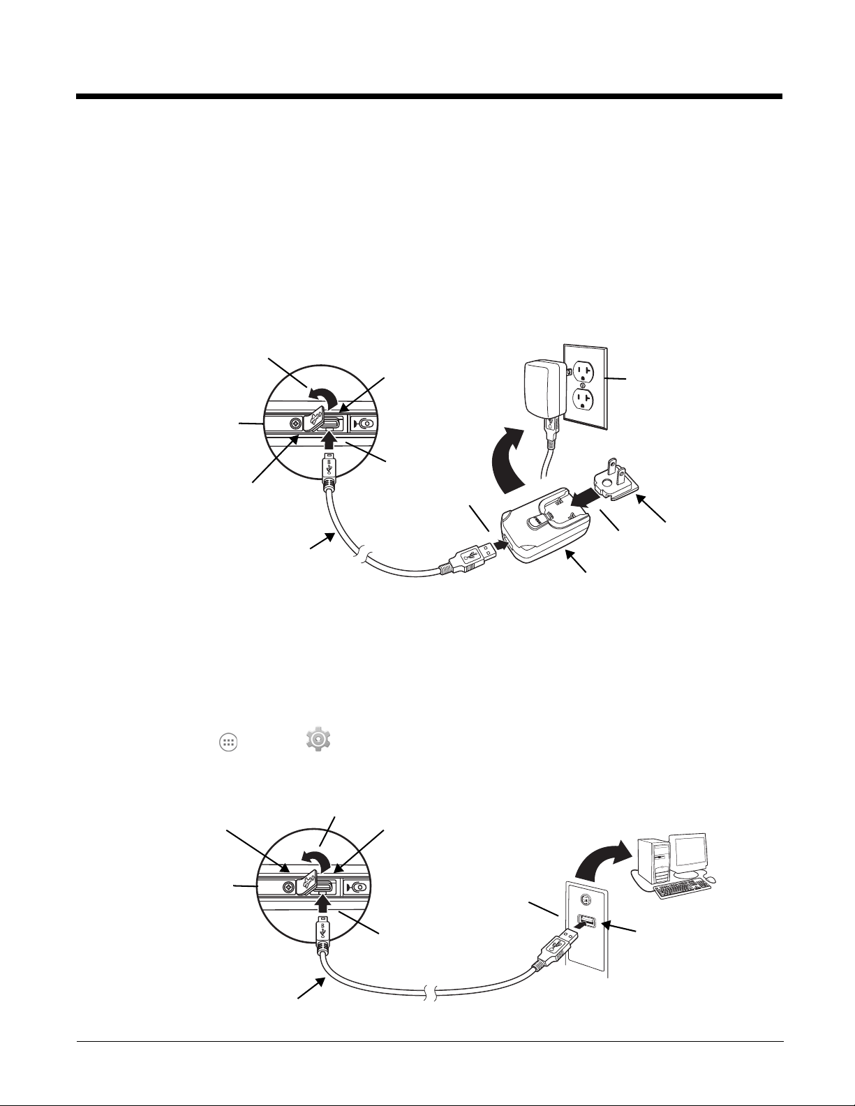
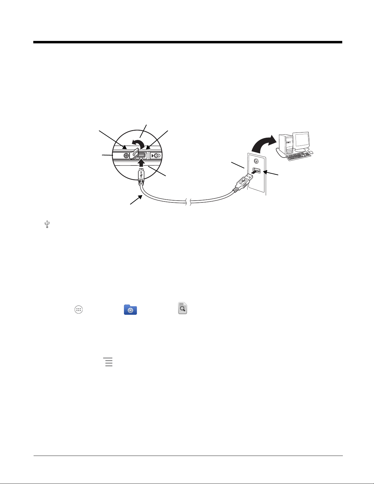
Using the USB Charge/Communication Cable (Model 70e-USB ADAPTERKIT)
USB Door
Plug Adapter
1
3
4
2
Micro USB Port
Power Adapter
5
Right Side Panel
of the Terminal
USB Charge/Communication Cable
USB Port on Host Device
USB Door
1
3
2
Micro USB Port
Right Side Panel
of the Terminal
USB Charge/Communication Cable
Preliminary Draft, Not for Release - Please Review 2-3-2015
Dolphin 75e terminals ship with a USB Charge/Communication Cable and a power adapter with regional plug
adapters. The USB Charge/Communication cable provides two options for charging the terminal. Use the cable in
conjunction with the provided power supply adapter and plug adapter to charge the terminal from a power outlet
(Option 1) or connect the cable to a high-power USB port to charge from a host device (Option 2).
Warning: The terminal shall only be connected to CTIA certified adapters, products that bear the USB-IF logo or
products that have completed the USB-IF compliance program when using the micro USB port as a
charging source.
Option 1: Charging from a power outlet
Use only a UL Listed power supply, which has been qualified by Honeywell with an output rated at 5VDC and 1A with
the device.
Option 2: Charging from a high power USB port on a host device (PC)
Charging the battery through a USB port takes more time than direct charging using the provided power supply.
Inadequate source current may lengthen the charge time or prevent the battery from charging if the terminal is drawing
more current than supplied by the USB port. The maximum current supplied by a USB Host can vary from 100mA to
500mA. Do not attempt to charge the terminal from a 100mA source. An active Dolphin terminal uses more current
than supplied by a 100mA source causing the terminal to continue to draw power from the battery. See Important
Charging Guidelines on page 3-10 for additional information.
To u ch All Apps > Settings > Battery to verify the battery is charging.
Note: Placing the terminal in Suspend mode while charging reduces the current draw of the terminal and shortens the
charging time of the battery.
2 - 3
Page 18
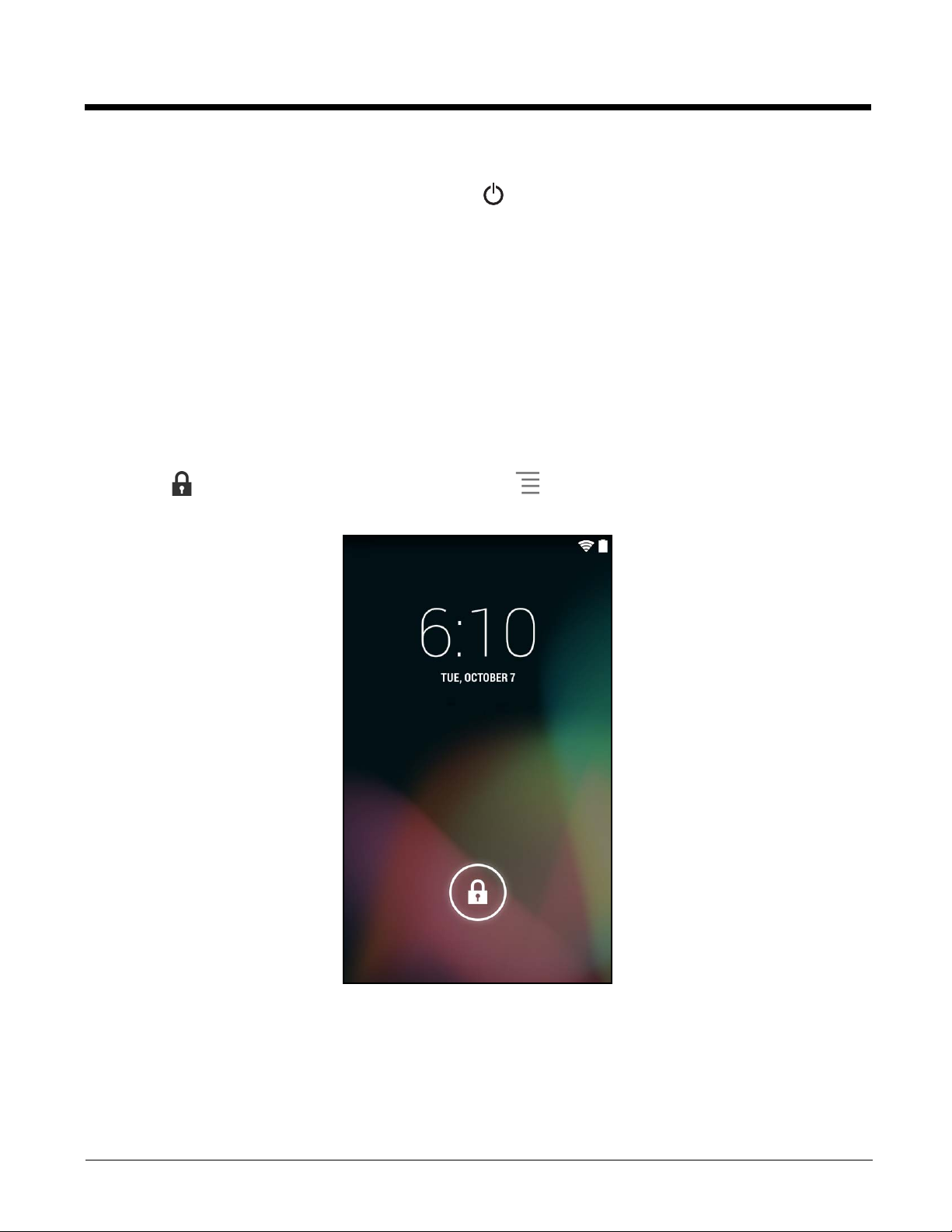
Power On the Terminal
Preliminary Draft, Not for Release - Please Review 2-3-2015
To turn the terminal On, press and release the Power button . Do not press any buttons or attempt to remove the battery
during the initial boot process.
The Welcome Screen
The first time you power up the Dolphin terminal, a Welcome screen appears after the boot process is finished. From
the Welcome screen follow the prompts as the Setup Wizard guides you through:
• setting the default language for the terminal,
• setting up Wi-Fi network connections,
• setting the time, date, and time zone, and
• personalizing (naming) the terminal.
After the initial Setup Wizard is complete the Locked Screen displays.
Note: Once you complete the initial Setup Wizard, the Welcome screen no longer appears when you reboot the device.
The Locked screen displays after the terminal completes the boot process.
Unlock the Screen
Drag the to the edge of the screen or press the Menu button to unlock the terminal and access the Home screen.
See Screen Security on page 6-4 for information on customizing the screen lock/unlock security feature.
2 - 4
Page 19
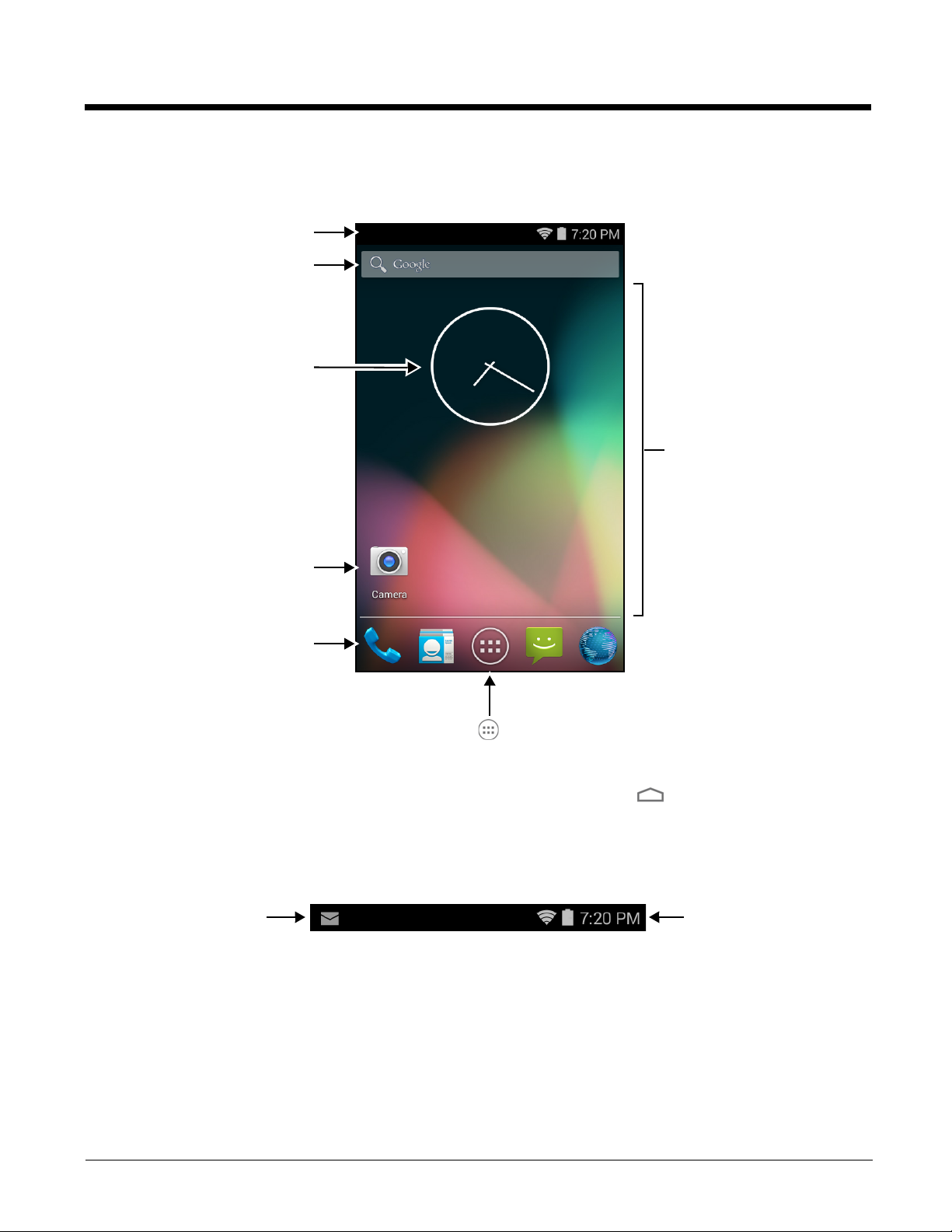
Customize the Home Screen and Access Apps
Tap the All Apps icon to view the apps and
widgets loaded on your device.
Notification/Status Bar
Search Bar
Home Screen Panel
Swipe left or right with your finger to
scroll between five Home screen
panels.
Personalize the panels with your choice
of app shortcuts, folders, and widgets.
Clock Widget
Camera App Shortcut
Favorites Tray
Notifications
Status Indicators and
Time Display
Preliminary Draft, Not for Release - Please Review 2-3-2015
The Android™ operating system provides space for user customization and control with five Home Screen panels.
Note: You can return to the Home screen at any time, in any application by pressing the button.
Status Bar
The status bar located at the top of the touch screen displays notifications (on the left), the status of various system
functions (on the right), and the current time (on the far right).
2 - 5
Page 20
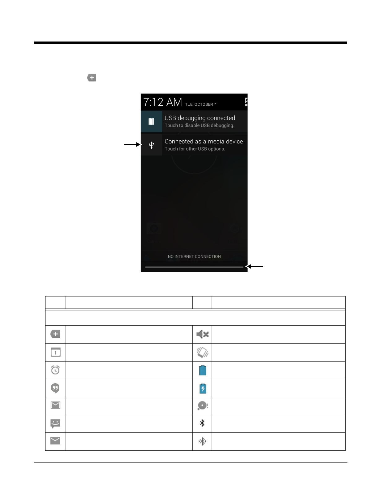
Notification Panel
Swipe up from the bottom of the screen
to close the notification panel.
Tap a notification to open
the related application.
Preliminary Draft, Not for Release - Please Review 2-3-2015
A plus sign icon appears on the status bar when the quantity of notifications exceed the available space on the bar.
To view all notifications, touch and hold the status bar, and then drag down.
Common Status and Notification Icons
Icon Meaning Icon Meaning
Note: Status and notification icons are hardware and software dependent. Some of the icons listed below may not be
relevant for your Dolphin model.
Open notification panel to see additional
notifications
Pending calender event Vibrate mode is turned on
Pending alarm and Alarm is set Battery charge is at 100%.
New Hangouts™ message Terminal is connected to external power and the
New Gmail™ message SD card or USB storage is full
New text message or multimedia message Bluetooth technology is turned on
New E-mail Terminal connected to a device with Bluetooth
Sound is turned off
battery is charging.
technology
2 - 6
Page 21
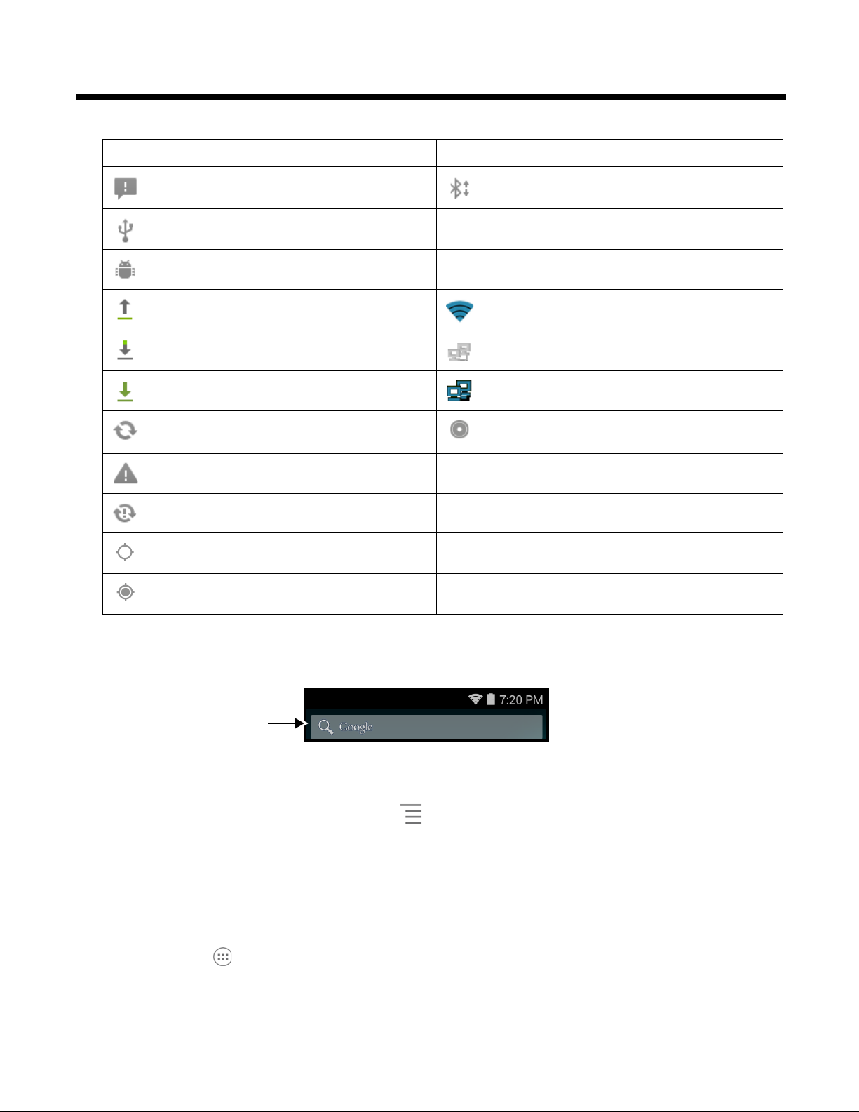
Icon Meaning Icon Meaning
Touch inside the box to
access the virtual keyboard
for text entry.
Preliminary Draft, Not for Release - Please Review 2-3-2015
Error with text or multimedia message delivery Bluetooth incoming file notification
Terminal is connected to a computer using a USB
cable
ABD active (USB debugging enabled)
Uploading data Wi-Fi network connected and signal strength
Downloading data Ethernet status - disconnected
Download finished Ethernet status - connected
Synchronizing data Music player active
Error with sync or sign-in
The terminal could not synchronize data with the
computer
GPS is turned on
Receiving location data from GPS
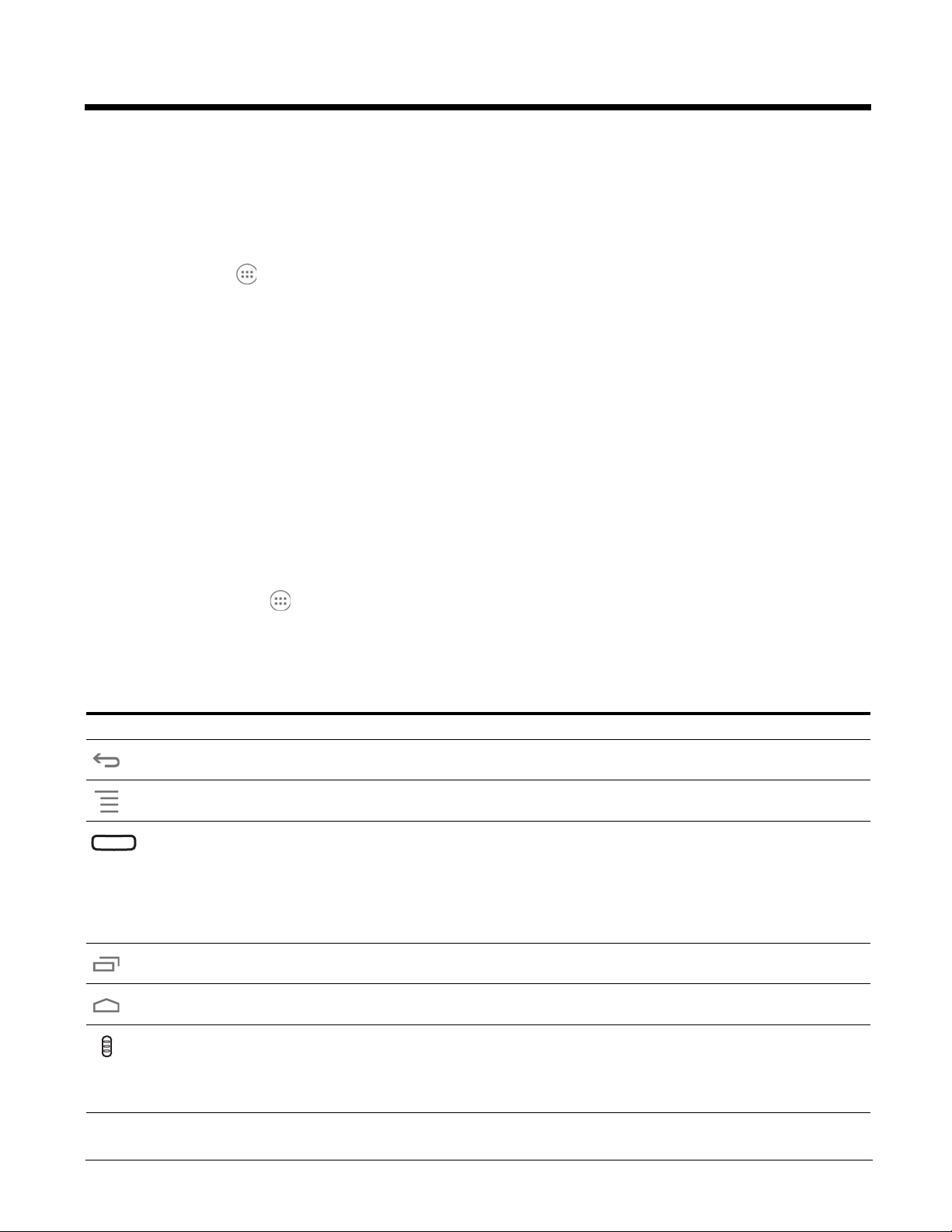
Search Bar
You can search for an item on the terminal or the Internet using Google™ Search at the top of any Home screen
panel.
To modify the search settings:
1. Touch inside the box then press the Menu button .
2. Touch Settings then select Searchable items or Google Search.
Personalize the Home Screen Panels and Favorites Tray
Streamline your work flow by customizing the Home screen panels and Favorites tray with your choice of app shortcuts,
folders, and widgets.
To add an app shortcut:
1. Touch All Apps .
2. Select and hold the app icon you want to add. The terminal vibrates, and then switches to the home screen.
3. Drag and drop the icon into position on the Home screen or in an open spot on the Favorites tray.
2 - 7
Page 22
Hints:
Preliminary Draft, Not for Release - Please Review 2-3-2015
• To create a folder, drag and drop an app icon on top of another icon.
• To move a shortcut from the Favorites tray to the Home screen panel, touch and hold the item, and then drag and
drop the icon onto the Home screen.
To add a widget:
1. Touch All Apps .
2. Select the Widget tab.
3. Touch and hold the widget you want to add. The terminal vibrates and switches to the Home screen.
4. Drag and drop the widget into the desired position.
To remove/delete an item:
1. Touch and hold the item.
2. Drag the item to the top of the screen where the word Remove is displayed.
To move an item:
1. Tap and hold the item.
2. When the unit vibrates, drag and drop the item in the new location.
Note: The next panel automatically opens if you drag the item to the edge of the touchscreen.
Apps and Widgets
To u ch t he All Apps icon located at the bottom of any Home screen to see the all apps and widgets loaded on your
terminal.
Navigation/Function Buttons
The Dolphin terminal has seven navigation/function buttons.
Button Function
Back Back to the previous screen.
Menu Opens additional menu options.
Scan Wakes the terminal from Suspend Mode.
Triggers the scanner/imager in the following apps: IQ Image Demo, Imaging Demo and Scan
Demo.
Triggers the scanner/imager when ScanWedge is enabled. Refer to the Dolphin Power Tools
User’s Guide available for download at www.honeywellaidc.com.
Recent Apps View and switch between recently used apps.
Home Return to the Home screen.
Right & Left
Side
Triggers the scanner/imager in the following apps: IQ Image Demo, Imaging Demo and Scan
Demo.
Triggers the scanner/imager when ScanWedge is enabled. Refer to the Dolphin Power Tools
User’s Guide available for download at www.honeywellaidc.com.
2 - 8
Page 23

Button Function
Preliminary Draft, Not for Release - Please Review 2-3-2015
Back Back to the previous screen.
Volume Raises or lowers the volume of the active speaker.
Hotkeys
You can configure the Scan button and the Left and Right side buttons of the terminal to launch specific applications.
To u ch All Apps > Power Tools > Configure Hotkeys . Touch the box next to the key being configured.
Select the app you want assigned to the key from the associated menu.
Refer to Features of the Dolphin 75e on page 3-3 for button locations on the terminal.
Virtual Keyboard
The virtual keyboard appears when you open an application or select a field that requires text or numerical input. The content of
the keyboard may vary depending on the application in use and the input field requirements.
Using the Virtual Keyboard
During text input, you may need to switch between keyboard modes to access additional character sets (e.g., function keys,
symbols, and numbers). Each keyboard mode, includes navigation keys, which allow you to quickly switch between modes.
Touch the ABC key to switch to the Qwerty Mode, the ?123 key to switch to the Numeric Mode. Touch and hold the comma
“,” key to access the settings for input options or the period “.” key to access additional symbols (e.g., @, %, +, &).
See Language & input on page 6-6 for additional information on configuring keyboard & input methods.
Note: The content of the keyboard and the mode initially displayed may vary depending on the application in use and the
input field requirements.
Turning Power On/Off
To turn the terminal On, press and release the Power button .
To turn the terminal Off:
1. Press and hold the Power button until the Options menu displays.
Note: If the Show System Dialog setting is turned off (see page 6-1), the Options menu does not display when you press
and hold the Power button. The terminal automatically reboots when Power button is held for approximately 8
seconds.
2. Touch Power Off.
You should always power off the terminal before removing the battery. For information on removing the battery, see Replacing
the Battery.
Suspend Mode
Suspend mode automatically turns the touch screen off and locks the terminal to save battery power when the terminal is
inactive for a programmed period of time.
1. Press and release the Power button to toggle the terminal in or out of Suspend mode.
Note: If the Power key setting has been turned off (disabled), pressing and releasing the key has no effect. See Display
Settings on page 6-1.
2 - 9
Page 24
2. Drag the to the right or press the Menu button to unlock the terminal.
!
Battery Door Lock
Preliminary Draft, Not for Release - Please Review 2-3-2015
To adjust the timeout limit, touch All Apps > Settings > Display > Sleep.
Airplane Mode
Turn On Airplane mode to disable all the terminal radios that transmit voice or data.
1. Press and hold the Power button until the Options menu displays.
2. Touch Airplane Mode to toggle the mode on or off. When Airplane Mode is turned on, shows on the status bar.
Note: If the Show System Dialog setting is turned off (see page 6-1), the Options menu does not display when you press and
hold the Power button. The terminal automatically reboots when Power button is held for approximately 8 seconds.
To enable Airplane mode when the Show System Dialog setting is off: touch > Settings . Under the “Wireless
& Networks” heading, select More. Check the box next to Airplane Mode.
Replacing the Battery
Before replacing the battery, read the Guidelines for Battery Pack Use and Disposal on page 3-11.
For battery replacement part numbers, see Replacement Battery Specifications on page 3-8.
RISK OF EXPLOSION IF BATTERY IS REPLACED BY AN INCORRECT TYPE. The battery should be disposed of
by a qualified re-cycler or hazardous materials handler. Do not incinerate the battery or dispose of the battery with
general waste materials.
Ensure all components are dry prior to mating terminals/batteries with peripheral devices. Mating wet components
may cause damage not covered by the warranty.
We recommend use of Honeywell Li-ion battery packs. Use of any non-Honeywell battery may result in damage not
covered by the warranty.
The following illustrations depict a standard battery with a standard battery door; however, battery removal and installation
procedures are the same for the extended battery and extended battery door.
To replace the battery:
1. Power Off the terminal.
2. Unlock and remove the battery door.
2 - 10
Page 25
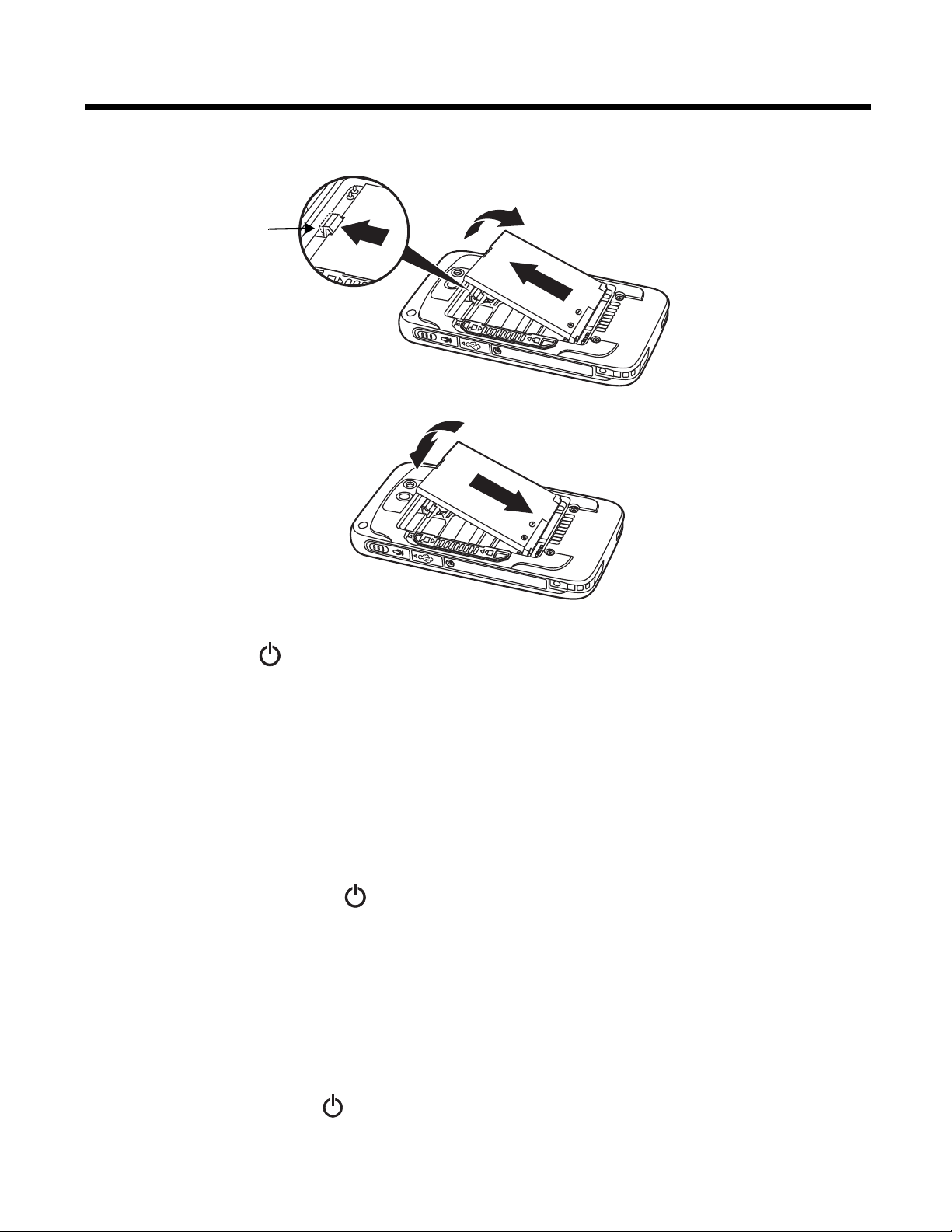
3. Pull the battery latch back and remove the battery.
Battery Latch
Preliminary Draft, Not for Release - Please Review 2-3-2015
4. Insert the new battery and install the battery door.
5. Apply pressure to the edges of the battery door to ensure the door is properly closed. Engage the door lock.
6. Press the Power button .
Important: All battery and connector doors must be present, undamaged, and properly closed to maintain the environmental
rating of the terminal.
Resetting the Terminal
There are two three types of system resets: a Hard Reset, a Soft Reset, or a Factory Reset. The hard or soft reset preserves
all data stored in the file system. Contact a Honeywell technical support representative for information on how to perform a
Factory Reset. For contact information, see Technical Assistance on page 14-1.
Hard Reset (Cold Boot)
A hard reset reboots the device and closes any open applications running in RAM at the time of the reset.
1. Press and hold the Power button until the Options menu displays.
Note: If the Show System Dialog setting is turned off (see page 6-1), the Options menu does not display when you
press and hold the Power button. The terminal automatically reboots when Power button is held for approximately
8 seconds.
2. Touch Reboot.
Soft Reset (Warm Boot)
A Soft Reset (Warm Boot) re-boots the device and preserves any objects created in RAM. You would perform a soft reset
when: the terminal fails to respond, after installing some software applications, or after making changes to certain system
settings, such as network cards.
Press and hold the Power button
complete, the Lock screen displays.
for approximately 8 seconds until the terminal starts to reboot. When the reset is
2 - 11
Page 26
Connecting the Terminal to a Computer via a USB Connection
USB Port on Host Device
USB Door
1
3
2
Micro USB Port
Right Side Panel
of the Terminal
USB Charge/Communication Cable
Preliminary Draft, Not for Release - Please Review 2-3-2015
You can transfer files (e.g., pictures, music, and videos) between your computer and the terminal using the supplied USB
Charge/Communication cable or a Dolphin 70e Black HomeBase with a standard USB cable.
Note: The terminal supports Hi-Speed USB communication (USB 2.0) with a maximum data transfer rate of 480 Mbps.
1. Connect the terminal to your computer using the USB Charge/Communication cable supplied.
On the status bar, the following notification briefly appears to indicate the hardware connection has been established:
Connected as a media device
2. The computer views the terminal as an external USB storage drive. You can now copy, delete and/or move files or folders
between the computer and the terminal or the microSD card installed in the terminal as you would with any other storage
drive (e.g., cut and paste or drag and drop).
3. When you are finished transferring files, follow the proper procedure for your computer’s operating system to safely remove
the hardware (e.g., unmount or eject) before attempting to disconnect the terminal from the computer or turning off the USB
storage setting. Data corruption may occur if the proper removal processes are not followed.
File Browser Power Tool
File Browser provides a graphical utility to browse the files stored on the terminal and the microSD card.
To u ch All Apps > Power Tools > File Browser to open the browser.
Touch a folder name or file name to open the folder or file.
Note: Due to system permissions, some files cannot be opened. Depending on the associated application(s), a choice of
applications may be available to open the file.
Browser Menu
Press the Menu button and touch Home to return to the root folder or Close to exit the File Browser.
\Honeywell
The Internal storage\Honeywell folder on the Dolphin terminal is semi-permanent storage on the terminal. By default, files
in this folder are maintained after a reboot.
Upgrades for the Power Tools and other system software on the Dolphin terminal come in the form of zip files. When the zip
files are placed in the \Internal storage\Honeywell\Autoinstall folder on the Dolphin terminal, they are automatically
installation after a Hard Reset (see page 2-11) if AutoInstall is enabled (see below). Upgrades are available the from
Customer Support (see page 14-1) or www.honeywellaidc.com.
Note: To copy the Power Tools upgrade files, an active USB connected session must be initiated between a host
2 - 12
workstation (see page 2-12).
Page 27
AutoInstall Settings
Preliminary Draft, Not for Release - Please Review 2-3-2015
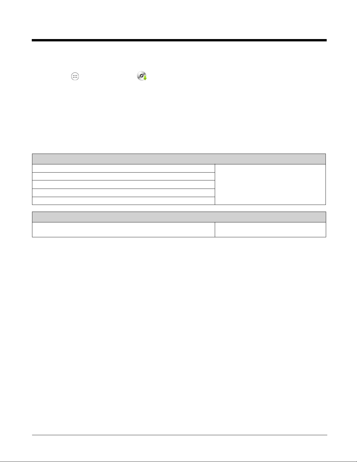
To u ch All Apps > AutoInstall Settings .
If AutoInstall is enabled, the Internal storage\Honeywell\Autoinstall folder on the Dolphin terminal is searched for zip files
containing applications. Each zip file is compared to the applications presently installed on the Dolphin terminal:
• If the application is not installed, AutoInstall installs the application.
• If the application is already installed, AutoInstall checks to see if the zip file contains a newer version of the application and
installs the newer version.
• If the application is already installed and there is not a newer version, AutoInstall ignores the installation file.
If AutoInstall is not enabled, the contents of the Internal storage\Honeywell\Autoinstall folder are ignored.
Additional Resources
Product Guides and Software Downloads
Dolphin 75e powered by Android Network & Security Guide Available for download from the Dolphin 75e
Dolphin 75e Black powered by Android Quick Start Guides
Dolphin Power Tools for devices powered by Android User’s Guide
Honeywell Software Development Kits (SDK)
Honeywell Tools and Utilities
Android OS
Android Developer Web Site
Detailed information on application development for Android devices.
product page at www.honeywellaidc.com.
http://developer.android.com
2 - 13
Page 28

2 - 14
Preliminary Draft, Not for Release - Please Review 2-3-2015
Page 29

3
Preliminary Draft, Not for Release - Please Review 2-3-2015
Hardware Overview
Standard Configurations for the Dolphin 75e
WLAN, WPAN & Camera
• Android 4.4
• Qualcomm APQ8074AB Processor
• 2GB RAM X 16GB Flash
• 3.7V Li-ion rechargeable standard or extended battery
pack
• Dedicated imager capable of decoding standard 1D and
2D bar code symbologies
• 8.0 megapixel auto focus color camera
• 802.11a/b/g/n/ac and Bluetooth
WLAN, WPAN, NFC & Camera
• Android 4.4
• Qualcomm APQ8074AB Processor
• 2GB RAM X 16GB Flash
• 3.7V Li-ion rechargeable standard or extended battery
pack
• Dedicated imager capable of decoding standard 1D and
2D bar code symbologies
• 8.0 megapixel auto focus color camera
• 802.11a/b/g/n/ac and Bluetooth
• Near Field Communication (NFC) support
Peripherals for the Dolphin 75e
Each of the following items is sold separately to enhance the capabilities of your Dolphin terminal. Dolphin 70e Black
peripherals are compatible with Dolphin 75e terminals.
Dolphin 70e Black HomeBase (Model 70e-HB)
The HomeBase is a charging and communication cradle equipped with a USB host port that is Hi-Speed 2.0v compliant,
which enables the terminal to interface with the majority of PC-based enterprise systems. This device also contains an
auxiliary battery well that charges a spare Honeywell standard or extended battery pack.
For more information, see Dolphin 70e Black HomeBase (Model 70e-HB) on page 9-1.
Dolphin 70e Black eBase (Model 70e-EHB)
The Ethernet Base (eBase) enables a single Dolphin 75e terminal to communicate with a host device over an Ethernet
network. In addition, the ebase is equipped with a USB host port that is Hi-Speed 2.0v compliant, which enables the
terminal to interface with the majority of PC-based enterprise systems. This device also contains an auxiliary battery well
that charges a spare Honeywell standard or extended battery pack.
For more information, see Dolphin 70e Black eBase (Model 70e-EHB) on page 10-1.
Dolphin 70e Black Mobile Base (Model 70e-MB)
The Mobile Base is a charging cradle designed specifically for in-premise and in-transit data collection applications. It
features a flexible mounting bracket, an integrated speaker with volume control, and a cigarette lighter adapter to adapt it to
your mobile environment.
For more information, see Dolphin 70e Black Mobile Base (Model 70e-MB) on page 11-1.
Dolphin 70e Black ChargeBase (Model 70e-CB)
The ChargeBase is a 4-slot charging cradle that holds, powers, and charges terminals.
For more information, see Dolphin 70e Black ChargeBase (Model 70e-CB) on page 12-1.
Dolphin 70e Black Net Base (Model 70e-NB)
The Net Base enables up to four Dolphin 75e terminals to communicate with a host device over an Ethernet network. In
addition, the Net Base provides a second RJ45 Ethernet port for connection to an additional device such as a printer,
workstation, eBase, or another Net Base.
For more information, see Dolphin 70e Black Net Base (Model 70e-NB) on page 13-1.
3 - 1
Page 30

QuadCharger (Model COMMON-QC)
Preliminary Draft, Not for Release - Please Review 2-3-2015
The QuadCharger is a compact 4-slot battery charging station designed for use with Dolphin 75e 3.7V Li-ion rechargeable
batteries. For additional information on the common QuadCharger, visit the Dolphin 75e product page at
www.honeywellaidc.com or contact your local sales representative.
Accessories for the Dolphin 75e
Each of the following items is sold separately to enhance your terminal’s capabilities.
Note: When using accessories where the terminal is worn on the body, the terminal’s touch panel must face away from the
body.
Dolphin 75e Mobile Charger (Model 70e-MC)
The Mobile Charger is a charging cable that connects the terminal directly to a 12 Volt DC power source, such as a
cigarette lighter port inside a vehicle, eliminating the need for a cradle. Intelligent battery technology on-board the terminal
ensures proper charging. The Mobile Charger is an ideal low-cost charging solution for in-transit mobile applications.
USB Charge/Communication Cable Adapter Kit (Model 70e-USB ADAPTERKIT)
The Dolphin USB charge/communication cable adapter kit is an all-in-one solution for charging and communication. Use
the 70e-USB cable in conjunction with the included power supply adapter and plug adapter to charge the terminal from a
power outlet or connect the cable to a high-power USB port to charge from a host device. The 70e-USB cable also supports
communication with a computer without the need for a cradle. See Connecting the Terminal to a Computer via a USB
Connection on page 2-12.
Holsters (Model HOLSTER-2 and 6000-HOLSTER)
A holster provides convenient storage for the Dolphin 75e terminal in mobile environments. Long and short holster models
with integrated belt clips and spare battery pouches are available.
Wrist Lanyard (Model SL-LANYARD-1)
The black wrist lanyard attaches to the bottom corner of the terminal providing additional security from accidental drop
during terminal use.
Stylus or Stylus and Tether Kit (Model 70e-Stylus or 70e-STYLUSTHR KIT)
The stylus has a special tip for added accuracy and ease when operating the touch panel. The tether is a coiled, elastic
cord, which secures the stylus to the terminal to prevent accidental loss. The stylus may be ordered with or without the
tether.
Stylus Battery Door Kits
Battery doors with an integrated stylus slot are available with or without a stylus and tether. The stylus has a special tip for
added accuracy and ease when operating the touch panel. The integrated slot in the battery door holds the stylus when not
in use. The tether is a coiled, elastic cord, which secures the stylus to the terminal preventing accidental loss when the
stylus is not properly stored in the slot. See Important Battery and Battery Door Replacement Guidelines on page 3-9
before ordering battery door kits for your terminal.
Battery (Models 70e-BTSC and 70e-BTEC)
The 3.7V Li-ion rechargeable battery provides the main power for the terminal. See Battery on page 3-8 for battery
specifications, replacement part numbers, and guidelines for use and disposal.
3 - 2
Page 31

Features of the Dolphin 75e
Recent Apps Button
Touch Panel Display
Scan Button
Front Speaker
Battery Charging Status and General Notification LED
Back Button
Front Digital Microphone
Scan Status Notification LED
USB Door/Micro USB Port
Menu Button
Right Scan/Image Button
Side Digital Microphone
Home Button
Bottom Speaker
Fastener for an Optional Wrist Lanyard
or Stylus Tether
Preliminary Draft, Not for Release - Please Review 2-3-2015
Front, Bottom, and Right Panels
For a description of each callout, see page 3-4.
Important: Do not cover the side microphone with your hand when using the terminal for handset VoIP calls.
3 - 3
Page 32

Feature Descriptions: Front, Bottom, and Right Panels
Preliminary Draft, Not for Release - Please Review 2-3-2015
Back Button
By default, the Back button returns you to the previous screen.
Bottom Speaker
The integrated bottom speaker sounds audio signals as you scan bar code labels and enter data. The integrated speaker
also supports playback of wave and MP3 files, software mixer, and speaker phone for VoIP audio.
Digital Microphone
The integrated dual array digital microphones, located on the side and front of the terminal provide audio input for handset
VoIP calls when a headset is not plugged into the Audio Jack, page 3-7. When a headset is plugged into the Audio Jack,
the terminal defaults to the microphone on the headset. By default, the front microphone is also used for speaker phone
calls, voice command audio input, and recording sound.
The digital microphones provide background noise cancellation for clear audio input.
Important: Do not cover the side microphone with your hand when using the terminal for handset VoIP calls.
Front Speaker
The front speaker is the receiver for handset VoIP calls.
Fastener for an Optional Wrist Lanyard or Stylus Tether
The fastener provides access for attaching an optional wrist lanyard or stylus tether.
Battery Charging Status and General Notification LED
The light emitting diode (LED) located above and to the right of the LCD display flashes and illuminates during resets and
taking a picture. When the terminal is connected to an AC power source, the LED indicates charging activity. This LED can
be programmed by various software applications.
Home Button
By default, the Home button returns you to the Home screen, see page 2-5.
Menu Button
Press the Menu button to access options relevant to the open application.
Right Scan/Image Button
By default, the right button triggers the scanner/imager. You can reassign the button to launch applications or execute
commands; see Hotkeys on page 2-9.
Recent Apps Button
The Recent Apps button allows you to view and switch between recently used apps.
Scan Button
The Scan button is centrally located for easy access with the right or left hand. When pressed, the Scan button activates
the scanner/imager when ScanWedge is enabled or a scanning/imaging demo app is open (e.g., IQ Image Demo, Scan
Demo). The Scan button also functions as a system wake-up control if the terminal has entered Suspend Mode. You can
reassign the button to launch applications or execute commands; see Hotkeys on page 2-9.
3 - 4
Page 33

Touch Panel Display
Preliminary Draft, Not for Release - Please Review 2-3-2015
The color 4.3 inch (liquid crystal display (LCD) touch panel is covered with an industrial, protective lens for greater
durability. The wide video graphic array (WVGA) display resolution is 800 X 480. The touch panel can be activated with a
finger or with the optional stylus.
The touch panel backlight illuminates when the screen is touched. To conserve battery power the touch screen dims then
darkens automatically after a period of no activity. Press the Power button, and then drag the unlock icon to the right or
press the Menu button to wake the terminal and access the last screen viewed. See Display Settings on page 6-1 for
information on how to adjust sleep (timeout) settings.
USB Door/Micro USB Port
The Micro USB port is located under the protective USB door on the right side of the terminal. To access the micro USB
port, gently lift the top edge of the door closest to the digital microphone.
The micro USB port in conjunction with the USB Charge/Communication Cable Adapter Kit powers the terminal, charges
the main battery, and facilitates communication. The micro USB port supports low, full, and high-speed USB v2.0 client
communication with a maximum rate of 480 Mbps.
For additional information, see Using the USB Charge/Communication Cable (Model 70e-USB ADAPTERKIT) on page 2-3
and Connecting the Terminal to a Computer via a USB Connection on page 2-12.
Scan Status Notification LED
The light emitting diode (LED) located above and to the left of the LCD display flashes and illuminates during scanning/
imaging to provide scan status information.
3 - 5
Page 34

Back, Top, and Left Panels
Image Engine Window (LED Aperture)
Camera Flash
Color Camera Lens
Battery Latch
(battery and battery door not shown)
Power Button
Left Scan/Image Button
I/O Connector (see
page 3-8)
Audio Jack
Volume Control Button
Battery Door
(Standard Model Shown)
Memory Retention Flap
Memory Card Socket
Battery Door Lock
Preliminary Draft, Not for Release - Please Review 2-3-2015
For a description of each callout, see page 3-7.
3 - 6
Page 35

Feature Descriptions: Back, Top, and Left Panels
Preliminary Draft, Not for Release - Please Review 2-3-2015
Audio Jack
The audio jack is located under the protective door on the top of the terminal. To access the jack gently lift the edge of the
door marked with an arrow. The 3.5mm audio jack supports both speaker (stereo) and microphone (mono) headsets.
Battery
The 3.7V Li-ion rechargeable battery provides the main power for the terminal and is protected by the battery door. See
Battery on page 3-8 for battery specifications, replacement part numbers, and guidelines for use and disposal.
Battery Door
The battery door protects the battery and any installed SIM and/or memory cards in the terminal’s battery well. Proper
installation of the battery door preserves the environmental rating of the terminal. Do not use the terminal without the
battery door installed.
Battery Door Lock
The battery door lock secures the battery door to the terminal. Slide the lock down toward the IO contacts to release the
lock for battery door removal and battery access. Slide the lock up toward the camera lens to secure the battery door
closed and seal the battery in the terminal. Proper installation of the battery door preserves the environmental rating of the
terminal.
Battery Latch
The battery latch secures the battery in the battery well. Pull the latch away from the battery to release and remove the
battery from the terminal. For information on Replacing the Battery, see page 2-10.
Color Camera
The 8.0-Megapixel Resolution color camera provides easy picture and video capture. The camera lens and camera flash
are located on the back panel of the terminal.
Camera Flash
The camera flash is located on the back panel of the terminal. When used as a Camera Flash with the integrated color
camera, the flash is controlled by the camera application.
Image Engine Window
The image engine reads and decodes linear, stacked linear (e.g., PDF417), and 2D matrix bar code symbologies. The LED
aperture for the imaging engine’s LED aimer is contained behind this window. For more details, see Using the Scan Image
Engine on page 4-1.
Left Scan/Image Button
By default, the left button triggers the scanner/imager. You can reassign the button to launch applications or execute
commands; see Hotkeys on page 2-9.
Memory Card Socket
The memory card socket provides the user with the option to expand the terminal’s memory capacity using microSD or
microSDHC memory interfaces. The expansion socket is located under the battery door and battery.
When the battery door and battery pack are properly installed, the card is sealed against moisture and particle intrusion,
read/write data is stored securely, and the terminal’s environmental rating is preserved; see Installing a Memory Card on
page 3-12.
Memory Retention Flap
The memory card retention flap locks the memory card in the socket; see Installing a Memory Card on page 3-12.
3 - 7
Page 36

Power Button
Pin 9 Pin 1
Preliminary Draft, Not for Release - Please Review 2-3-2015
The Power button located on the top of the terminal initiates multiple functions depending on the length of time the
button is pressed.
• A quick press of the button toggles Suspend Mode On or Off. To modify this feature, see Power Key on page 6-2.
• Press and hold the button down for approximately 4 seconds to access the Options menu to Power Off the terminal,
Reboot (Hard Reset) the terminal, enable Airplane Mode, set the Volume of the active speaker to On, Off, or Vibrate.
To modify this feature, see Show System Dialog on page 6-2.
• Press and hold the button down for approximately 8 seconds to initiate a manual Reboot (Soft Reset) if the touch screen
has stopped responding.
Volume Control Button
Press the top or bottom of the volume button to raise or lower the volume of the active speaker. Lower the volume all the
way down to turn off the volume and enable vibration mode.
The I/O Connector
The I/O connector powers the terminal, charges the main battery, and facilitates communication. Dolphin 75e peripherals are
designed to work exclusively with this connector. The I/O connector supports low, full, and high speed USB v2.0 communication
with a maximum rate of 480 Mbps.
Pin Signal Description Terminal Back Panel
1 VDC_IN 5V DC input for charging and operation
2 VBUS_HOST 5V output for USB host and peripheral power
3 USB_DM_HOST USB D- for the host port
4 USB_DP_HOST USB D+ for the host port
5 USBC_DET Multipurpose pin to allow for detection of an
unpowered SLED, determine SLED type, and to
signal a HomeBase the docking of the terminal.
6 GND Ground connection
7 USB_DN_DOCK USB D- for the client port
8 USB_DP_DOCK USB D+ for the client port
9 VBUS_DOCK 5V input for USB client (and charging)
Note: Signals referenced are for a DTE device.
Battery
The primary power source for the Dolphin terminal is the 3.7V Li-ion rechargeable battery located under the battery door on the
back panel of the device. Honeywell recommends, you keep the battery in the terminal charged at all times to help prevent data
loss. Letting the battery become fully discharged causes the terminal to lose all data in RAM.
Note: All data in RAM is cleared when the battery is removed. Always power off the terminal before removing the battery to
ensure any changes made are saved to the flash memory.
Replacement Battery Specifications
Dolphin 75e model terminals are designed for use with battery part numbers BAT-STANDARD-02 (Li-ion 3.7V, 6.179 watt
hour) and BAT-EXTENDED-02 (Li-ion 3.7V, 12.358 watt hour) manufactured for Honeywell International Inc. See page 2-10
for battery replacement instructions.
3 - 8
Page 37

Important Battery and Battery Door Replacement Guidelines
!
Preliminary Draft, Not for Release - Please Review 2-3-2015
Follow the guidelines listed below when ordering batteries and/or battery doors.
• Size (e.g., standard or extended): The battery and battery door must be the same size.
• Type (e.g., locking or non-locking): The battery and battery door must match your terminal type. See details above.
Replacement kit numbers 70e?
• Near Field Communication (NFC) requirements: Use only NFC compatible battery doors with NFC equipped Dolphin
models identified with a letter N at the end of the model number (e.g., 75exxN).
We recommend use of Honeywell Li-ion battery packs. Use of any non-Honeywell battery may result in damage
not covered by the warranty.
Important: All battery and connector doors must be present, undamaged, and properly closed to maintain the
environmental rating of the terminal.
Charging Options
Dolphin 75e terminals ship with the battery significantly discharged of power. Before using a terminal for the first time,
charge the battery with a Dolphin charging device for a minimum of 4 hours for the standard battery and 6 hours for the
extended battery. When using the 70e-USB Charge/Communication cable to charge from a 500mA USB port on a host
device, charge the battery for a minimum of 6 hours for the standard battery and 8 hours for the extended battery.
When the main battery is installed in the terminal, use one of the following:
• Dolphin 70e Black HomeBase (Model 70e-HB), see page 9-1
• Dolphin 70e Black eBase (Model 70e-EHB), see page 10-1
• Dolphin 70e Black Mobile Base (Model 70e-MB), see page 11-1
• Dolphin 70e Black ChargeBase (Model 70e-CB), see page 12-1
• Dolphin 70e Black Net Base (Model 70e-NB), see page 13-1
• Dolphin 70e USB Charge/Communication Cable (Model 70e-USB ADAPTERKIT) included with terminal, see page 2-3
When the main battery is not installed in the terminal:
• Place the battery pack in the Auxiliary Battery Well of the Dolphin 70e Black HomeBase (Model 70e-HB) or the Dolphin
70e Black eBase (Model 70e-EHB).
• Insert the battery in the QuadCharger (Model COMMON-QC), see page 3-1.
Charging Time
Charging Peripheral/Accessory
HomeBase (Model 70e-HB) 4 hours 6 hours
eBase (Model 70e-EHB) 4 hours 6 hours
ChargeBase (Model 70e-CB) 4 hours 6 hours
Net Base (Model 70e-NB) 4 hours 6 hours
Mobile Base (Model 70e-MB) 4 hours 6 hours
Mobile Charger (Model 70e-MC) 4 hours 6 hours
USB Charge/Communication Cable with provided power
supply (Model 70e-USB ADAPTERKIT)
USB Charge/Communication Cable (Model 70e-USB)
connected to a workstation (PC) 500mA USB port
QuadCharger (Model COMMON-QC) 4 hours 6 hours
Model: 70e-BTSC Model: 70e-BTEC
BAT-STANDARD-02 BAT-EXTENDED-02
4 hours 6 hours
6 hours 8 hours
3 - 9
Page 38

Important Charging Guidelines
Preliminary Draft, Not for Release - Please Review 2-3-2015
Source Current Specifications
Battery charging times can be significantly lengthened or charging may not occur if the terminal is drawing more
currant than is supplied by the charging peripheral (e.g., HomeBase, eBase, Mobile Base, or ChargeBase), USB wall
charger, or USB Host (e.g., workstation PC).
• The maximum current supplied through a charging peripheral is 2.0A.
• The maximum current supplied by the USB wall charger is 900mA.
• The maximum current supplied by a USB Host can vary from 100mA to 500mA.
Do not attempt to charge the terminal from a 100mA source. An active Dolphin terminal uses more current than
supplied by a 100mA source causing the terminal to continue to draw power from the battery.
Note: Placing the terminal in Suspend mode while charging reduces the current draw of the terminal and shortens the
charging time of the battery.
To verify the battery is charging, touch All Apps > Settings > Battery.
Charging a Severely Low or Completely Discharged Battery
Battery Charge Status Symptom
Severely Low Pressing the Power button does not wake the terminal from Suspend mode. The
general notification LED may flash once when the Power button is pressed.
Completely Discharged Pressing the Power button does not wake the device and the general notification LED
remains off.
Use one of the following options to charge a severely low or completely discharged battery.
• Insert the battery into the auxiliary battery well of the HomeBase. When the auxiliary battery LED on the HomeBase
turns green, the battery is fully charged.
• Dock the terminal into the charging well of a peripheral (e.g., HomeBase, eBase, Net Base or ChargeBase). The
terminal starts to boot as soon as power is supplied by the base. To prevent the possible loss of unsaved data, do not
remove the terminal from the base until the battery has sufficiently charged.
Touch > Settings > Battery to view detailed information on the status of the battery.
• Charge the terminal from a wall power outlet using the USB Charge/Communication Cable and power supply provided
with your terminal. As the battery charges, the general notification LED cycles through green, red, amber and off. The
LED continues to cycle until the battery reaches a safe charge threshold and the terminal begins to boot. The length
of time before the battery reaches a safe charge threshold varies depending on the extent of the battery discharge. If
the general notification LED does not start to cycle after approximately 5 seconds when power is applied, press the
Power button once.
• Charge the terminal from a USB host device (PC) using the USB Charge/Communication Cable. As the battery
charges, the general notification LED cycles through green, red, amber and off. The LED continues to cycle until the
battery reaches a safe charge threshold and the terminal begins to boot. The length of time before the battery reaches
a safe charge threshold varies depending on the extent of the initial battery discharge level and the current supplied
by the USB charging source. If the general notification LED does not start to cycle after approximately 5 seconds when
power is applied, press the Power button once.
Inadequate source current may interfere with effective battery charging; see Important Charging Guidelines on page
3-10 for additional information.
Managing Battery Power
Letting the battery become fully discharged causes the terminal to lose all data in RAM. Honeywell recommends, you keep
a charged battery in the terminal at all times to help prevent data loss. Removing the battery from the terminal erases all
non-persistent memory.
When the terminal is running on battery power (as opposed to external power), warnings are displayed when the battery
reaches critical and low battery points.
3 - 10
Page 39

Checking Battery Power and Monitoring Battery Power Use
Touch an item to view usage
details and adjust power use.
Battery level and
Battery status.
Touch to view History
details.
Preliminary Draft, Not for Release - Please Review 2-3-2015
To u ch All Apps > Settings > Battery to display information the battery status (charging or discharging), the
level (percentage) of charge remaining on the battery, and a breakdown of battery usage statistics for any running
apps and services.
Storing Batteries
To maintain top performance from batteries, avoid storing batteries outside of the following temperature ranges:
• 14°F to 113°F (-10°C to +45°C) for short term storage of less than one month
• 32°F to 86°F (-0°C to +30°C) for long term storage
Do not store batteries in extremely high humidity. For prolonged storage, do not keep batteries stored in a charger that is
connected to a power source.
Guidelines for Battery Pack Use and Disposal
The following are general guidelines for the safe use and disposal of batteries:
• Do not disassemble or open crush, bend or deform, puncture or shred.
• Do not modify or remanufacture, attempt to insert foreign objects into the battery, immerse or expose to water or other
liquids, expose to fire, explosion or other hazard.
• Improper battery use may result in a fire, explosion or other hazard.
• We recommend use of Honeywell Li-ion battery packs. Use of any non-Honeywell battery may pose a personal hazard
to the user.
• Only use the battery for the system for which it is specified. Do not use a battery in any other manner outside its intended
use in Dolphin terminals and peripherals.
• Only use the battery with a charging system that has been qualified with the system per standard IEEE-Std-1725-2006.
Use of an unqualified battery or charger may present a risk of fire, explosion, leakage, or other hazard.
• Replace the battery only with another battery that has been qualified with the system per this standard, IEEE-Std-1725-
2006. Use of an unqualified battery may present a risk of fire, explosion, leakage or other hazard.
• Replace defective batteries immediately; using a defective battery could damage the Dolphin terminal.
3 - 11
Page 40

• Never throw a used battery in the trash. Promptly dispose of used batteries in accordance with local regulations.
Battery Door Lock
Preliminary Draft, Not for Release - Please Review 2-3-2015
• Do not short-circuit a battery or throw it into a fire; it can explode and cause severe personal injury. Do not allow metallic
conductive objects to contact battery terminals.
• If you observe that the Honeywell battery supplied is physically damaged, please send it to Honeywell International Inc.
or an authorized service center for inspection, see Product Service and Repair on page 14-1.
• Battery usage by children should be supervised.
• Avoid dropping the terminal or battery. If the terminal or battery is dropped, especially on a hard surface, and the user
suspects damage, send it to a Honeywell International Inc. or an authorized service center for inspection.
• If you are not sure the battery or charger is working properly, send it to Honeywell International Inc. or an authorized
service center for inspection, see Product Service and Repair on page 14-1.
• Excessive discharge can degrade battery performance. Recharge the battery when your terminal indicates low battery
power.
• Although your battery can be recharged many times, the battery life is limited. Replace it after the battery is unable to
hold an adequate charge.
• The Dolphin 75e should only be connected via its microUSB connector to CTIA certified adapters, products that bear the
USB-IF logo or products that have completed, the USB-IF compliance program.
System Resets
See Resetting the Terminal on page 2-11.
Hardware Maintenance
When needed, clean the image engine window and the touch screen with a clean, non-abrasive, lint-free cloth. The terminal can
be cleaned with a damp cloth.
Important: All battery and connector doors must be present, undamaged, and properly closed to maintain the environmental
rating of the terminal.
Installing a Memory Card
You can expand the terminal’s memory capacity by installing a microSD or microSDHC card. Honeywell recommends the use of
Single Level Cell (SLC) industrial grade microSD or microSDHC memory cards with Dolphin terminals for maximum
performance and durability. Contact a Honeywell sales representative for additional information on qualified memory card
options.
Note: Format memory card before initial use.
Installation and/or Replacement
To install a memory card:
1. Power Off the terminal.
2. Unlock and remove the battery door.
3 - 12
Page 41

3. Pull the battery latch back and remove the battery.
Battery Latch
Memory Card
(contacts facing down)
Retention Flap
Memory Card Socket
Preliminary Draft, Not for Release - Please Review 2-3-2015
4. Lift the card retention flap, slide the memory card (contacts facing down) into the socket, and then close the retention
flap.
5. Install battery and battery door. Apply pressure to the edges of the battery door to ensure the door is properly closed,
and then engage the door lock.
6. Press the Power button .
3 - 13
Page 42

3 - 14
Preliminary Draft, Not for Release - Please Review 2-3-2015
Page 43

4
Preliminary Draft, Not for Release - Please Review 2-3-2015
Using the Scan Image Engine
Overview
The Dolphin 75e terminal houses a compact image engine that instantly reads popular 1D and 2D bar codes and supports
omni-directional aiming and decoding for greater flexibility in real-world settings. The image engine can also capture black and
white digital images, such as signatures and pictures of damaged inventory.
With the latest CMOS-based technology, the engine works like a digital camera and enables black and white digital image
capture, signature capture, and reading of OCR characters.
LED Safety
See Canadian Compliance, Conformité à la règlementation canadienne on page 1-2.
Image Engine Specifications
Field of View
Horizontal Field Angle (°) 21.9+/-0.5 degree
Vertical Field Angle (°) 15.9+/-0.5 degree
Depth of Field
The depth of field measurements used the following parameters:
• Distances are measured from the front of the engine.
• +23°C (+73°F), 0 lux
• Photographic quality codes
Symbology
3 mil C39/128 - - -
5 mil C39/128 2.25 (5.7) 4.35 (11.049) 2.1 (5.3)
7.5 mil C39/128 1.25 (3.2) 6.87 (17.4) 5.62 (14.3)
10 mil C39/128 0.67 (1.7) 9.93 (25.2) 9.26 (23.5)
15 mil C39/128 1.01 (2.6) 15.16 (38.5) 14.15 (35.94)
20 mil C39/128 1.80 (4.57) 18.56 (47.14) 16.76 (42.57)
100% 13 mil UPC 1.57 (3.9) 12.18 (30.9) 10.61 (26.9)
5 mil PDF417 - - -
6.7 mil PDF417 1.53 (3.8) 4.63 (11.7) 3.1 (7.8)
10 mil PDF417 1.38 (3.5) 7.34 (18.6) 5.96 (15.1)
5 mil microPDF - - -
5 mil DataMatrix - - -
10 mil DataMatrix 1.52 (3.8) 4.87 (12.3) 3.35 (8.5)
20 mil DataMatrix 1.07 (2.7) 9.66 (24.5) 8.59 (21.8)
10 mil QR 1.50 (3.8) 5.13 (13.0) 3.63 (9.2)
20 mil QR 2.48 (6.3) 9.66 (24.5) 7.18 (18.2)
32 mil Maxicode 1.56 (3.9) 13.19 (33.5) 11.63 (29.5)
Distance (in/cm)
Near
Distance (in/cm)
Far
Delta (in/cm)
4 - 1
Page 44

Supported Bar Code Symbologies
Preliminary Draft, Not for Release - Please Review 2-3-2015
Symbology Type Symbology Name
1D Symbologies
2D Symbologies
Composite Codes
OCR
Postal Codes
Codabar
Code 3 of 9
Code 11
Code 32 Pharmaceutical (PARAF)
Code 93
Code 128
EAN with Add-On
EAN with Extended Coupon Code
EAN-8
EAN-13
GS1-128
GS1 Databar
Aztec
Codablock A
Codablock F
Data Matrix
UPC/EAN
UCC/EAN
GS1 Databar
MICR E 13-B
OCR-A
OCR-B
Postnet and most international 4-state codes
Australian Post
British Post
Interleaved 2 or 5
ISBT 128
Matrix 2 of 5
MSI Plessey
Straight 2 of 5 IATA
Straight 2 of 5 Industrial
Telepen
Trioptic Code
UPC with Add On
UPC-A
UPC-E
GS1 Databar
MaxiCode
Micro PDF
PDF417
QR Code
Canadian Post
China Post
Decoding
The terminal supports image decoding for use in various bar code reading and imaging applications. Full-area imaging provides
omni-directional reading of linear and non-linear 1D and 2D bar codes, OCR, signature capture, and picture taking. When
reading all bar code types using full-area imaging, a positive read can be obtained from many positions; see Aiming Beam on
page 4-6 To achieve the best read, the aiming beam should be centered horizontally across the bar code.
Using the Scan Demo to Decode a Bar Code
The Scan Demo demonstrates the functionality of the integrated scan image engine in the terminal and is not intended as a
functional business solution. Detailed information on how to create custom applications for your Dolphin terminal is
provided in the Software Development Kit (SDK), available for download at www.honeywellaidc.com.
1. Touch All Apps > Demos > Scan Demo to open the Scan Demo application.
2. Point the Dolphin terminal at the bar code. For optimum performance, avoid
reflections by scanning the bar code at a slight angle.
3. Touch and hold Scan or press and hold the Scan button. Center the aiming beam
over the bar code; see Aiming Beam on page 4-6.
Note: By default, the left and right side buttons also trigger the scan/imager.
4 - 2
Page 45
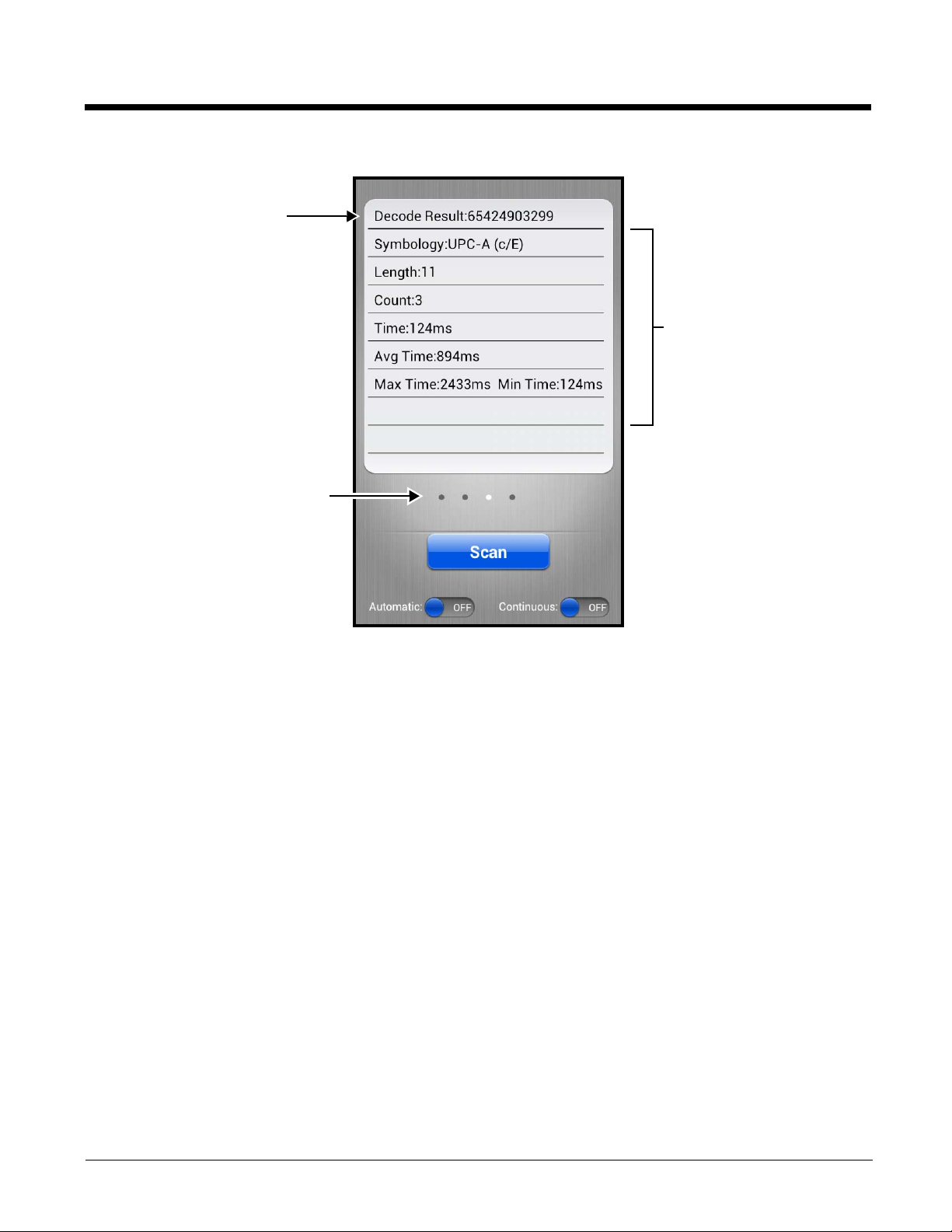
4. The bar code is decoded and the results appear on the screen.
Decode Results
Touch the dots or swipe left or
right to scroll through the
decode results of past scans.
Scan Statistics
See Configuring the Scan Demo
Application on page 4-4.
Preliminary Draft, Not for Release - Please Review 2-3-2015
Automatic Scanning
Enable Automatic scanning mode to activate the imager for continuous scanning without requiring the operator to touch
Scan for each bar code presented in the field of view of the imager. To configure the time interval between scan attempts,
see Auto Scan Delay under Configuring the Scan Demo Application (page 4-4).
1. Slide the Automatic blue button to the ON position to enable the feature.
2. Touch Scan or press the Scan button to activate the imaging engine. Once activated, the imager automatically scans
and decodes bar codes presented in the field of view.
3. Touch Scan or press the Scan button to deactivate the imager.
4. Slide the Automatic blue button to the OFF position to disable the feature.
Continuous Scanning
Enable Continuous scanning mode to activate the imager for continuous scanning only when the operator touches and
holds Scan or presses and holds the Scan button. The time interval between scan attempts is minimal and not
configurable.
1. Slide the Continuous blue button to the ON position to enable the feature.
2. Touch and hold Scan or press and hold the Scan button to activate the imaging engine.
The imager scans and decodes bar codes presented in the terminal’s field of view as long as Scan or the Scan button is
pressed.
3. Release Scan or the Scan button to deactivate the imager.
4. Slide the Continuous blue button to the OFF position to disable the feature.
4 - 3
Page 46

Configuring the Scan Demo Application
Touch Symbology Setting to access
the Symbologies Settings screen.
Touch Setting to access the Scan
Demo settings screen.
Preliminary Draft, Not for Release - Please Review 2-3-2015
1. Open the Scan Demo application, and then press the Menu button .
2. Touch Setting or Symbology Setting .
3. Modify the settings to meet your application needs, and then press the Back button to return to the Scan Demo
screen.
Settings Touch the checkbox to enable or disable a feature.
Symbology
Settings
4 - 4
• Vibrate - When checked, the terminal vibrates to indicate a successful bar code scan and
decode.
• View Statistics - When checked, scan results displayed include the length of bar code, the
number of scans completed, the number of milliseconds (ms) to decode the bar code, the
average decode time of all the bar codes decoded, the shortest decode time of all bar codes
decoded, and the longest decode time of all bar codes decoded.
• Sound - When checked, the terminal emits sound to indicate a successful or failed scan
attempt.
• Auto Scan Delay - Program the number of seconds between scan attempts by tapping the
menu arrow, and then entering the delay interval in second. The value should be greater
than 0 and less than 100000. Touch OK to save.
• Auto Send - When checked, decoded data is sent to a designated server.
• RF Configuration - Touch to view and/or edit the Server IP address and the Port used for
RF communication. When the Back button is pressed, the terminal attempts to establish
communication.
Touch the box next to the symbology name to toggle the symbology on (enabled) or off
(disabled). A green check mark indicates the symbology is enabled.
Note: Swipe up or down with your finger or stylus on the screen to scroll up or down the list
of available symbologies.
Page 47

Check the box to
enable a symbology.
Touch to access the advanced
symbology settings.
Preliminary Draft, Not for Release - Please Review 2-3-2015
Using the ScanTool Power Tool
Note: Detailed information on the ScanTool Power Tool is provided in the Dolphin Power Tools for Mobile Devices Powered
by Android™ User’s Guide, available for download at www.honeywellaidc.com.
1. Touch All Apps > Power Tools > ScanTool .
2. Touch one of the Quick Start applications.
Quick Start Application Description
Activity result Scan and decode bar codes
Show result Scan, decode, and view the results (i.e., bar code type and value)
Send via SMS Scan, decode, and send the results via SMS
Send via MMS Scan, decode, and send the results via MMS
Send via email Scan, decode, and email the results
Send to application Quick start an application by scanning a barcode
Settings Modifies the imager symbology settings
About Displays ScanTool version and copyright information
3. The device automatically scans and decodes the bar code when the application is selected.
Symbology Settings Menu
1. Touch All Apps > Power Tools > ScanTool > Settings.
2. Touch the box next to the symbology name to toggle the symbology on (enabled) or off (disabled). A green check
mark indicates the symbology is enabled.
Note: Swipe up or down with your finger or stylus on the screen to scroll up or down the list of available symbologies.
4 - 5
Page 48

3. Touch the arrow box to view and modify the advanced settings (e.g. suffix, prefix, minimum and maximum length)
Preliminary Draft, Not for Release - Please Review 2-3-2015
for the symbology.
Aiming Beam
The aiming beam is smaller when the terminal is held closer to the code and larger when it is farther from the code.
Symbologies with smaller bars or elements (mil size) should be read closer to the unit whereas symbologies with larger
bars or elements (mil size) should be read farther from the unit.
Linear Bar Code.
2D Matrix Symbol
Capturing Images
The image-capture process is an intuitive, split-second operation for experienced users. By following the basic guidelines, new
users can easily develop their own technique and, with practice, quickly learn to adapt it to different application environments.
Image Preview: When the imaging process is initiated, the touch screen displays a preview of the object. This is a live
video image of what the imager is currently viewing. The live video image has a slightly degraded appearance compared to
the captured image. This is normal.
File Formats: File formats supported for image storage include JPEG (JPG) and Portable Network Graphics (PNG). The
default file format for images is a grayscale JPG.
Compression: Digital images have a maximum image size of 832 x 640 pixels and may have up to a 256 grayscale image
definition. The image quality and related file size are determined by the data compression method used by the software
application used to take images. The average size of the image file is approximately 400–800K. However, the size of the
image depends on the content of the image - the more complex the content, the larger the file size.
Taking an Image with the Imaging Demo
The Imaging Demo demonstrates the functionality of the integrated scan image engine in the terminal and is not intended
as a functional business solution. Detailed information on how to create custom applications for your Dolphin terminal is
provided in the Software Development Kit (SDK), available for download at www.honeywellaidc.com.
To capture an image using the Imaging Demo application:
1. Touch All Apps > Demos . Swipe left to scroll to the Imaging Demo, and then touch .
4 - 6
Page 49

2. Point the Dolphin terminal at the object.
Preliminary Draft, Not for Release - Please Review 2-3-2015
3. Adjust the terminal’s position until the object appears on the touch screen the way you want it to appear in the image.
Note: Touch the to toggle the targeting cross hair on the touchscreen on or off.
4. Touch or press the Scan button to capture the image.
5. To save the captured image, press the Menu button.
6. Touch File, and then either select:
• Save to save the image to the default location
(mnt/sdcard/honeywell/imagedemo)
OR
• Save As to select a different location to save the image.
Using the IQ Image Demo to decode intelligent bar codes and capture images
Decode an intelligent bar code, insert the data into predefined data fields, and capture an image of the bar code using the
IQ Image Demo. The demo includes four format options: Delivery, Postal, Embed, and No format. Each format is
designed to decode data from bar codes specifically coded to match the format of the option screen.
Note: The IQ Image Demo demonstrates the functionality of the integrated scan image engine in the terminal and is not
intended as a functional business solution. Detailed information on how to create custom applications for your Dolphin
terminal is provided in the Software Development Kit (SDK), available for download at www.honeywellaidc.com.
1. Touch All Apps > Demos . Swipe right to scroll to the IQ Image Demo, then touch .
2. Touch one of the four format options: Delivery, Postal, Embed, or No format.
3. Point the Dolphin terminal at the intelligent bar code.
4. Touch Scan or press the Scan button.
5. The decode results (e.g., Tracking Number and Address embedded in the bar
code) automatically populate the fields on the screen.
Note: You don’t need to clear the field to take another scan, just activate the image engine again.
6. Press the Menu button, and then tap File to save an image of the scan or bar code. The file is saved in the mnt/sdcard/
honeywell/iqdemo folder on the microSD card.
Configuring the IQ Image Demo Application
1. Open the IQ Image Demo application, and then touch one of the four configuration options (i.e., Delivery, Postal,
Embed or No format).
2. Press the Menu button.
3. Touch Setting to access and modify the following options:
•Select Symbology to configure the type of symbologies you want the IQ Imaging Demo to decode. Touch the
symbology’s checkbox to enable or disable the symbology. Press the back button to return to the IQ Imaging screen.
•Select Image Type to choose Binary or Grayscale.
•Select Sound to toggle audible feedback on or off for successful scans.
4 - 7
Page 50

Using the Signature Demo
Touch screen signature area.
Touch to clear signature
screen without saving.
Date Stamp
Touch to save image
of signature.
Touch to toggle Date
Stamp on or off.
Touch to adjust the pen width of
the signature displayed on the
screen.
Preliminary Draft, Not for Release - Please Review 2-3-2015
The Signature Demo captures a signature on the touch screen.
1. Touch All Apps > Demos . Swipe right to scroll to the Signature Demo, then touch .
2. Using a finger or the optional stylus, sign the touch screen.
3. Touch .
4. Enter a name for the of the image file you want to save, and then select the file type: JPG or PNG.
5. Touch Save. The signature image file is saved in the mnt/sdcard/honeywell/signaturedemo folder on the microSD card.
Uploading Images
Image files can be uploaded to a host workstation using a USB connection, see page 2-12.
4 - 8
Page 51

5
Camera Lens
Camera Flash
Preliminary Draft, Not for Release - Please Review 2-3-2015
Using the Color Camera
Overview
Dolphin 75e terminals are equipped with 8.0-Megapixel auto focus cameras to provide easy integration of color picture and
video capture into business applications. The camera lens and camera flash are located on the back panel of the terminal.
Pictures and videos captured using the Camera app are stored on the micorSD card in the DCIM folder under Camera
(mnt\sdcard\DCIM\Camera). You can copy your pictures and videos to a computer (see page 2-12) or view, edit, and share your
pictures and videos using the Gallery app.
Opening the Camera app and Adjusting the Settings
To open the Camera app, do one of the following:
• If the slider screen lock is activated, drag the lock icon to the Camera icon .
OR
• Touch the Camera icon on the Home screen.
If the Camera app does not initialize, verify ScanWedge is disabled.
Adjusting the Camera/Video Settings
The camera/video settings are adjustable from within the Camera app.
• Use the slider bar to adjusts the zoom in (+) or out (-).
• Touch to adjust: White balance, Flash, Exposure for pictures, and Time lapse interval for videos.
• Touch then to: set the Picture size (pixels), set the Focus mode, enable or disable storing the location in the picture/
video file, or to restore the camera defaults.
Taking a Picture
1. Open the Camera app (see page 5-1).
2. Verify is selected.
3. Center the object you want to take a picture of on the live preview screen.
4. Touch to capture the picture.
5 - 1
Page 52

Note: Touch the thumbnail preview to access options to share the picture. Select the picture again to open the Gallery app
Preliminary Draft, Not for Release - Please Review 2-3-2015
where you can edit or delete the picture by pressing the Menu button.
6. Press the Back button to close the app.
Taking a Panoramic Picture
1. Open the Camera app (see page 5-1).
2. Touch to switch to panorama mode.
3. Point the camera lens at the beginning of the scene you want capture.
4. Touch to start capturing the picture. Slowly sweep the camera lens across the scene using the touchscreen preview as
a guide.
Note: Touch the thumbnail preview to access options to share the picture. Select the picture again to open the Gallery app
where you can edit or delete the picture by pressing the Menu button.
7. Press the Back button to close the app.
Recording Video
1. Open the Camera app (see page 5-1).
2. Touch to switch to video mode.
3. Point the camera lens at the scene or object you want to capture in video.
4. To start capturing video, touch .
5. Use the slider bar to zoom in (+) or out (-) while recording.
6. To stop capturing video, touch .
Note: Touch the thumbnail preview to access options to share the video. Select the video again to open the Gallery app
where you can delete the video by pressing the Menu button and selecting Delete.
7. Press the Back button to close the app (see page 5-1).
Uploading Pictures and Videos
Picture and Video files can be uploaded to a computer using a USB connection. For additional information, see page 2-12.
5 - 2
Page 53

6
Preliminary Draft, Not for Release - Please Review 2-3-2015
Settings
Overview
The Settings allows you to verify and/or alter system parameters to customized your terminal to meet your specific needs. Touch
All Apps > Settings or pull down the notification panel, and then touch the Settings icon next to the date.
Wireless & Network Settings
See "Wireless & Networks Settings" on page 7-1 and Establishing Ethernet Communication on page 10-6.
Device Settings
Sound Settings
Touch Sound from the Settings screen then select the configuration setting you want to modify.
• Volumes - Set the volume level used for music, videos, games, other media, ring tones, notifications, and alarms.
• Silent Mode - Turn silent mode on or off, enable vibration feedback, or mute audio output.
• Ringtone & Notifications - Set the phone ringtone, default sound for notifications, and turn vibration on or off for
incoming calls.
• System - Set sound and vibration feedback during touch screen interaction.
Display Settings
Touch Display from the Settings screen to set the touch screen Brightness level, Wallpaper, turn Auto-rotate
screen on or off, adjust the touch screen Sleep settings, set the on screen Font size, and enable or disable some Power
button functions.
6 - 1
Page 54

Auto-rotate screen
Phone Options Menu
Preliminary Draft, Not for Release - Please Review 2-3-2015
By default, the display automatically adjusts the orientation of the screen between landscape and portrait when the
terminal is rotated. Touch the Auto-rotate screen checkbox to toggle the option on or off.
Sleep
The Sleep setting enables you to customize backlight functionality for the display. Select how many minutes or
seconds you want to elapse before the backlight automatically turns off and the terminal enters Suspend mode (see
page 2-9).
Show System Dialog
By default, the Phone Options menu displays when you press and hold the Power
button . To disable access to the Phone Options menu using the Power
button , uncheck the box next to Show System dialog.
Power Key
By default, the terminal can be placed into Suspend mode (see page 2-9) by
briefly pressing the Power button . To disable entering Suspend mode using
the Power button , uncheck the box next to Power Key.
Unattended mode
By default, the Wi-Fi radio is turned off when the terminal enters Suspend mode to reduce battery use and increasing
time between charge cycles. To keep the Wi-Fi radio on when the terminal enters Suspend mode, uncheck the box
next to Unattended mode.
Honeywell Smart Sensors Settings
To u ch Honeywell Smart Sensor from the Settings screen to configure the integrated motion detection sensors for
advanced power management.
• Keep awake on motion - When enabled, the terminal is prevented from entering Suspend mode when motion is
detected. By default, this option is disabled.
• Wake on motion - When enabled, the terminal wakes from Suspend mode when motion is detected. By default, this
option is disabled.
• Face down suspend - When enabled, the terminal enters Suspend mode when placed face down on a flat surface. By
default, this option is disabled.
Storage Settings
To u ch Storage from the Settings screen to view use and space statistics for the internal storage on the terminal and
the installed SD card. Two additional options: Unmount SD card for safe SD card removal and Erase SD card for erasing
all data on the installed SD card are also available from the Storage screen.
Battery Settings
See "Managing Battery Power" on page 3-10.
Apps Settings
To u ch Apps from the Settings screen to view, evaluate, and modify how applications installed on the terminal or SD
card utilize memory and storage resources.
Note: You can also reach the Apps screen from the Home screen by pressing the Menu button, and then selecting Manage
apps.
Touch the tabs at the top of the Apps screen to view lists organized into four categories:
6 - 2
Page 55

• Downloaded
Preliminary Draft, Not for Release - Please Review 2-3-2015
Displays all apps downloaded to the terminal.
To sort the list, press the Menu button , and then touch Sort by size or Sort by name.
• On SD Card
Displays only apps designed to be stored either on the SD card or on the internal storage of the terminal. A green
checkmark indicates the app is stored on the SD card. Apps that prohibit movement do not appear on the list.
• Running
Displays application processes and services running on the terminal and cached background processes. Touch Show
cached processes or Show running services at the bottom of the screen to switch between the lists.
• All
Displays all apps stored either on the SD card or on the internal storage of the terminal.
To sort the list, press the Menu button , and then touch Sort by size or Sort by name.
Displayed at the bottom of each category screen is the memory or storage type, the amount of storage or memory used by
the listed applications, and the amount of free space remaining.
Managing Apps
The App info screen contains detailed statistics on an app including the amount of storage or cache utilized, default launch
settings, and access permissions granted to the app. Statistics useful when troubleshooting slow terminal performance, low
memory issues, or an unresponsive application. The App info screen also provides access to perform the following
actions:
• force stop the app,
• uninstall the app,
• move the app to either the SD card or phone (limited by app permissions),
• clear stored data,
• clear cache, or
• clear any Launch by default settings assigned to the app.
To access the App info screen, touch the app name on the list displayed under the Downloaded or On SD Card tab on the
Settings > Apps screen.
Uninstall Applications
1. Press the Menu button from the Home screen, and then touch Manage apps.
2. Touch the application you want to uninstall.
3. Touch Uninstall, and then OK to confirm.
Move Applications
1. Press the Menu button from the Home screen, and then touch Manage apps.
2. Touch the On SD Card tab.
3. Touch the application you want to move.
Note: A green checkmark indicates an application is stored on the SD card.
4. Touch Move to SD card or Move to phone to move the application.
Note: Applications moved to the SD card still require the use of a minimal amount of internal storage on the terminal.
Stop Application Processes or Services
1. Press the Menu button from the Home screen, and then touch Manage apps.
2. Touch the Running tab.
3. Touch the cached background process or running service you want to stop.
4. Touch Stop.
6 - 3
Page 56

Personal Settings
Preliminary Draft, Not for Release - Please Review 2-3-2015
Accounts & sync
To u ch Accounts & sync from the Settings screen to add, remove, and manage exchange accounts (e.g., e-mail) and
allow apps to automatically schedule and sync data.
To add an account:
1. Touch All Apps > Settings > Accounts & Sync.
2. Touch Add account.
3. Touch the type of account to add.
4. Follow the on-screen instructions to enter the required information for the account type selected. You may need to
provide a user name and password, select security settings, and configure data sync preferences during the setup.
5. The account appears on the Accounts & Sync list when setup is complete. Depending on the settings you selected
during the account configuration, your terminal may automatically start to sync account data (e.g., email, contacts,
music and calendar).
Note: Touch the account name on the list to view Data & Synchronization settings.
To remove an account:
1. Touch All Apps > Settings > Accounts & Sync.
2. Touch the account to delete.
3. Press the Menu button , and then select Remove account.
4. Touch Remove account to confirm deletion.
Security
To u ch Security from the Settings menu to manage terminal security parameters (e.g., authorization for device
administration, setup a screen lock, setup a SIM card PIN, enable/disable visible passwords, load security certificates, and
setup a password to protect the terminal's credential storage).
Screen Security
The Screen Lock settings provide access to additional security features that enable you to prevent an unauthorized
person from unlocking the touch screen and accessing the terminal. Select from five security options: None, Slide,
Pattern, PIN or Password.
• To enable a screen lock:
Touch on Pattern, PIN or Password to access additional dialogue screens that step you through setting up or
updating the security feature.
• To disable a screen lock:
Touch Security from the Settings screen. Select Screen Lock, and then enter your existing Pattern, PIN, or
Password. Touch Next and then select None to remove the security setting.
Once you have established a screen lock, additional settings may appear under the Screen Security heading
depending on the type of security you implemented. The additional settings allow you to adjust the time increment for
the screen to Automatically lock after entering Suspend (sleep) mode and enable or disable Vibration on touch
during security input.
The Owner Info setting allows you to designate custom text you want displayed on the lock screen. You can also
disable owner information from displaying.
6 - 4
Page 57

Encryption
Preliminary Draft, Not for Release - Please Review 2-3-2015
You can encrypt all the data on your Dolphin terminal using the Encrypt phone option as an advanced security
measure in case your device is ever lost or stolen. When the terminal is encrypted, you must enter a numeric PIN or
password each time you turn the power on. The Screen Lock PIN or password you set up is the same PIN or
password used for encryption security and cannot be set independently.
Warning: You cannot reverse encryption. The only way to revert back to an unencrypted state is to perform a factory
reset, which erases all your data.
SIM card lock
To u ch Set up SIM card lock to establish or modify a SIM card PIN so unauthorized individuals cannot use the terminal
as a phone or modify data on the SIM card.
Passwords
Touch the Make passwords visible checkbox to toggle between hiding or showing passwords as you type.
Device Administration
The Device administrators screen lists all applications that have been given authorization to act as a device
administrator, which is often required when you set up accounts that synchronize data between the terminal and an
enterprise service. An enterprise service implements security policies on the terminal before allowing a connection
(e.g. passwords and certificates). Touch Device administrators from the Security screen, and then touch the
application name if you want to remove authorization for the app to act as a device administrator for the terminal.
Check the Unknown sources box to allow the installation of non-market applications. This setting is disabled by
default.
Credential Storage
Access options that help you manage your Wi-Fi network and/or Virtual Private Network (VPN) security certificates
under the Credential storage heading at the bottom of the Security settings screen.
Note: Android supports DER-encoded X.509 certificates saved with a .crt or .cer file extension and X.509 certificates
saved in PKCS#12 key store files with a .p12 or .pfx file extension.
Trusted credentials
To u ch Trusted credentials from the Security screen to view all the security credentials installed on the terminal. Tabs
organize the certificates into two categories: System and User. Touch the certificate name to view additional details
about the certificate.
To disable a system certificate or remove a user certificate:
1. Touch the certificate name from the Trusted credentials System or User list.
2. Scroll to the bottom of the Security certificate details screen.
3. Touch Disable or Remove depending on the type of certificate you are viewing.
Note: System certificates can be Enabled using the same method at a later date but User certificates are permanently
deleted.
4. Select OK.
Install from SD Card
To install encrypted certificate from the SD card installed in the terminal:
1. Copy the certificate from the host device (computer) to the root directory of the SD card.
Note: Ensure your certificates are saved with the correct file extension. Android supports DER-encoded X.509
certificates saved with a .crt or .cer file extension and X.509 certificates saved in PKCS#12 key store files with a
.p12 or .pfx file extension.
6 - 5
Page 58

2. Touch All Apps > Settings > Security > Credential Storage.
Preliminary Draft, Not for Release - Please Review 2-3-2015
3. Touch Install from SD card.
4. Touch the file name of the certificate to install and enter a password if required.
5. Touch OK.
6. Enter the name of the certificate, and then touch OK.
Note: Once an encrypted certificate is installed on the terminal, it is automatically deleted from the SD card.
Language & input
To u ch Language & input from the Settings screen to access options to modify the default language for the display, change the
automatic spelling correction settings, manage your personal dictionary, configure keyboard & input methods for text entry,
manage speech settings for voice searches and text-to-speech output and set the mouse/trackpad pointer speed.
Language
Touch All Apps > Settings > Language & input > Language, and then select the language you want displayed
on the touch screen.
Spelling Correction
Touch All Apps > Settings > Language & input > Spelling correction to turn the feature on or off.
Touch to change the language settings when the feature is turned on.
Personal Dictionary
Touch All Apps > Settings > Language & input > Personal Dictionary to add, edit, or delete words from your
personal dictionary.
Keyboard & Input Methods
The virtual keyboard appears when you open an application or select a field that requires text or numerical input. The
content of the keyboard may vary depending on the selected default, the application in use, and the input field
requirements.
To modify the default method for entering text, touch All Apps > Settings > Language & input > Default.
Touch next to the keyboard name to adjust settings specific for the keyboard type (e.g., Keyboard Skin, Vibrate on Key
Press, Sound on Key Press, Show Key Preview, Show Settings Key, and Input Language Preference).
To configure Text-to-speech (TTS) settings, touch All Apps > Settings > Language & input > Text-to-speech
output. The settings screen provides access for you to:
• Select and configure the preferred engine used for speech synthesis when you want to hear text
read aloud.
• Adjust the Speech rate of the synthesized voice.
• Listen to an example of speech synthesis based on the current settings.
Mouse/Trackpad
Touch All Apps > Settings > Language & input > Pointer Speed to adjust the sensitivity and
speed of the touch screen response to your finger swipe.
6 - 6
Page 59

Backup & reset
Preliminary Draft, Not for Release - Please Review 2-3-2015
To u ch Backup & reset from the Settings screen to access options for backing up and restoring your data, settings, and
account information on the terminal. There are three options available under the Backup & Restore heading:
• Back up my data - Touch to enable or disable backing up your app data, Wi-Fi passwords, and other settings to Google
servers. The Backup account and Automatic restore options are only selectable if this option is enabled.
• Backup account - Touch to configure and sign into the Google account used for backing up your terminal data.
• Automatic restore - Touch to enable or disable the automatic restoration of previous app settings and data from the
backup server when you reinstalling an app.
System
Date & Time
To u ch Date & time from the Settings screen to access options to configure the date, time, time zone, time format, and
date format displayed on the terminal. You can set the terminal to synchronize the date and time using a network
connection by checking the Automatic date & time box or you can manually enter the values by touching Set date, Set
Time, or Select Time zone.
Note: If the Automatic option is checked, the Set date, Select Time zone, and Set time menu options are
grayed out.
To modify how the time is displayed on the screen, check the Use 24-hour format box to switch from a 12-hour cycle to a
24-hour cycle. In a 24-hour time cycle, 1:00 pm displays as 13:00 pm.
To change the date format displayed on the screen, touch Select date format, and then select a format from the list.
Accessibility
To u ch Accessibility from the Settings screen to configure features that make using the terminal easier for people
with certain physical disabilities.
Services
When the TalkBack service app is enabled, spoken and vibration feedback help blind and vision-impaired users
interact with the terminal. The spoken feedback includes descriptions of what you touch, select, and activate.
To enable or disable the TalkBack service app, select TalkBack on the Accessibility screen then touch the ON/OFF
toggle box in the upper right corner of the screen.
System
Under the System heading on the Accessibility screen, additional options are available to enable or disable Large Text,
touch screen Auto-rotation, spoken passwords, or ending calls using the Power button . You can also set Touch &
hold delay settings and permissions for Installing web scripts.
Developer options
To u ch Developer options from the Settings screen to access advanced settings used by Android application
developers. For information on these settings, Android APIs, and development tools, refer to the Android developer web site
at http://developer.android.com.
About Phone
The About Phone screen displays specific information about the terminal including: Model number, Android OS version,
Baseband version, Kernel version, Build number, and RIL version.
To u ch System Updates to view the last time the Android operating system was updated or to manually initiate an Android
update.
To u ch Legal information to view important information on Open source software licenses.
6 - 7
Page 60

To u ch Status to view following terminal information:
Preliminary Draft, Not for Release - Please Review 2-3-2015
• battery status,
• remaining charge level of the battery,
• signal strength,
• service state,
• Wi-Fi MAC address,
• Bluetooth address, and
• serial number.
Note: The content of the About phone and Status screen are base on the terminal model type.
6 - 8
Page 61

7
Preliminary Draft, Not for Release - Please Review 2-3-2015
Communication
Wireless & Networks Settings
Under the Wireless & Networks heading on the Settings screen there are options for turning the onboard wireless radios in
the terminal on or off and for configuring network connections.
Connecting the Terminal to a Wireless Network
You connect the terminal to a wireless network through the on-board radios (802.11a/b/g/n and/or Bluetooth). Each radio has its
own configuration utility and requires specific information about the wireless network to connect. A successful connection
depends on your network infrastructure so you may need to consult your network administrator before attempting a connection.
WLAN (802.11a/b/g/n/ac)
The Dolphin 75e has a 802.11a/b/g/n/ac WLAN (Wireless Local Area Network) radio. The radio is interoperable with other
802.11a/b/g/n, Wi-Fi compliant products including access points (APs), workstations via PC card adapters, and other
wireless portable devices.
Bluetooth
See "Working with Bluetooth and NFC Technology" on page 8-1.
7 - 1
Page 62

Wi-Fi Network Connections
Preliminary Draft, Not for Release - Please Review 2-3-2015
Turning Wi-Fi Networking On or Off
1. Touch All Apps > Settings .
2. Touch the Wi-Fi OFF/ON toggle box to turn the radio or .
Connecting to a Wi-Fi Network
1. Touch All Apps > Settings > Wi-Fi.
2. Verify the Wi-Fi is turned .
3. The terminal searches for available Wi-Fi access points within range of the device. If the terminal previously connected
to a Wi-Fi network, it automatically reconnects to the same network.
To remove a Wi-Fi network the terminal previously connected to, touch the network name, and then touch Forget, to
delete the stored network information.
4. Touch the network name you want to connect to from the available network list.
5. If the network is secured, a dialog box appears requesting information relevant to the network security protocol (e.g.,
password, key, or certificate). Enter the required information.
6. Touch Connect.
Receiving Network Notifications
If Wi-Fi networking is turned On, you can set the terminal to notify you when an open network is available.
1. Touch All Apps > Settings > Wi-Fi.
2. Press the Menu button , and then touch Advanced.
3. Touch the check box to toggle Network notification On (checked) or Off.
Adding a Wi-Fi Network
1. Touch All Apps > Settings > Wi-Fi.
2. Verify the Wi-Fi is turned .
3. Touch Add Network located at the bottom of the available Wi-Fi network list.
4. Enter the Network SSID (Wi-Fi network name).
5. For secure Wi-Fi network connections, touch None under Security, and then select the type of security protocol
required from the pop-up menu (e.g., WEP, WPA/WPA2 PSK or 802.1xEAP).
6. Enter any additional security information required by the type of security protocol selected.
7. Touch Save.
Advanced Wi-Fi Settings and Network Utilities
Advanced Wi-Fi Menu
The Advanced Wi-Fi menu provides access to set network notifications, modify Wi-Fi radio activity during Suspend mode,
idle timeout settings, or view the terminal MAC address and IP address.
7 - 2
Page 63

• Network notification
Preliminary Draft, Not for Release - Please Review 2-3-2015
Turn on or off available Wi-Fi network notification.
• Keep Wi-Fi on during sleep
Set how the Wi-Fi radio reacts when the terminal enters sleep (Suspend) mode (i.e., Always, Only when plugged in, or
Never).
• Wi-Fi idle timeout.
Adjust how long the Wi-Fi may be idle before the radio is automatically turned off (i.e., 1 minute, 3 minutes, 15 minutes
(default), 30 minutes, 1 hour, or 3 hours)
•MAC address
• IP address
To access the advanced Wi-Fi menu settings:
1. Touch All Apps > Settings .
2. Under Wireless & Networks, touch Wi-Fi.
3. Press the Menu button .
4. Select Advanced.
Wi-Fi Radio Settings Power Tool
The Wi-Fi Radio Settings network utility provides several options for advanced configuration of the
Wi-Fi 802.11 radio in the terminal. Select from the five tabs at the bottom of the utility screen to access the following settings:
• 2.4GHz Channel
Identify the channels to be used for 2.4GHz communication.
• 5GHz Channel
Identify the channels to be used for 5GHz communication.
• Roaming
Enable/disable roaming, adjust the roaming threshold, define the AP Diff value (dBm), set the roaming scan period, or
enable/disable Dynamic Frequency Selection (DFS) roaming.
• Tx Rates
Identify the Tx Rates (e.g., CCK, OFDM, DMN) to be used.
• Other
Modify power save options (i.e., Auto, Short Doze, Long Doze).
Enable/disable Wi-Fi Multimedia Extensions/Quality of Service (WMM/QoS).
Enable/disable Random AP selection and set the Random AP minimum RSSI value.
Specify the Beacon Loss Count.
To u ch All Apps > Power Tools > Wi-Fi Radio Settings .
Note: Refer to the User’s Guide for Dolphin Power Tools for Mobile Devices powered by Android for additional information.
Product guides are available for download at www.honeywellaidc.com.
Wireless Manager Power Tool
The Wireless Manager network utility provides access to the Wi-Fi Manager where you can view and change the status of the
terminal radios, scan and add networks, view current access point statistics, select your network firmware and set your hyper
roaming preferences.
To u ch All Apps > Power Tools > Wireless Manager .
Note: When the Wireless & Network screen appears, an arrow is displayed to the left of the highest priority wireless network
connection. To change the priority, touch and hold on the text for the preferred connection, and then select OK.
Touch the ON/OFF toggle box ( or ) next to the radio name to change the power status.
To u ch Wi-Fi to access the Wi-Fi Manager and:
• Create a Wi-Fi favorites list.
7 - 3
Page 64

• Scan and add networks.
Preliminary Draft, Not for Release - Please Review 2-3-2015
• View general information on current and scanned access points.
• View detailed information on the current access point and roaming statistics.
Note: On the Power Tools screen, select Connection Manager for direct access the manager without opening the
Wireless Manager .
Note: Refer to the User’s Guide for Dolphin Power Tools for Mobile Devices powered by Android for additional information.
Product guides are available for download at www.honeywellaidc.com.
Airplane Mode
See "Airplane Mode" on page 2-10.
Virtual Private Networks (VPN)
To complete the VPN setup screens, you may need to ask your ISP or network administrator for the proxy server name, server
type, port, type of Socks protocol used, and your user name and password if you do not already have the information.
Adding a VPN
1. Touch All Apps > Settings .
2. Under Wireless & Networks, touch More > VPN.
Note: VPN connections require you to set a screen lock PIN or password before you can use credential storage. If you have
not set either security option, select OK on the pop-up notification window, and then set a screen lock PIN or
password. Once you complete the process, you are automatically directed back to the VPN screen.
3. Touch Add VPN network.
4. Enter the VPN Name, and then select the VPN Type you want to add. Complete the remaining data fields with the
appropriate information for your network. The terminal supports the following protocol types:
• PPTP
• L2TP/IPSec PSK
• L2TP/IPSec RSA
• IPSec Xauth PSK
• IPSec Xauth RSA
• IPSec Hybrid RSA
5. Touch Save.
Note: To delete a VPN, touch and hold the network name on the VPN screen, and then touch Delete network.
To edit a VPN configuration, touch and hold the network name on the VPN screen, and then touch Edit network.
Touch Save to retain your changes.
Connecting to a VPN
1. Touch All Apps > Settings .
2. Under Wireless & Networks, touch More > VPN.
3. Touch the name of the VPN.
4. Enter any security credentials (e.g., password, user name, certificate information or server name) required by the VPN.
5. Touch Connect.
Note: When a VPN connection is established, a shows in the status bar.
7 - 4
Page 65

Disconnecting from a VPN
Preliminary Draft, Not for Release - Please Review 2-3-2015
1. Drag the status bar down from the top of the touch screen to view the Notification panel.
2. Touch the VPN connection notification to disconnect.
Ethernet Communication
See "Establishing Ethernet Communication" on page 10-6.
7 - 5
Page 66

7 - 6
Preliminary Draft, Not for Release - Please Review 2-3-2015
Page 67

8
Preliminary Draft, Not for Release - Please Review 2-3-2015
Working with Bluetooth and NFC Technology
Bluetooth Technology
Turning the Bluetooth Radio On or Off
Bluetooth™ is a short-range wireless communications technology used to exchanged data between devices over a
distance of approximately 26.2 feet (8 meters). Before you can connect or pair your terminal to another device using
Bluetooth technology, you must first turn on the Bluetooth radio.
1. Touch All Apps > Settings .
2. Touch the Bluetooth OFF/ON toggle box to turn the radio on .
Once the Bluetooth radio is activated, the terminal automatically starts searching for discoverable devices.
Note: System bar icons at the top of the touchscreen indicate the status of the Bluetooth radio.
Pairing and Trusted Devices
The terminal supports pairing with other devices using Bluetooth technology. Pairing happens during general connection
setup. Paired devices are “trusted” devices. This means that there is unrestricted access to all services (including services
that require authorization and authentication).
Connecting to Other Bluetooth Devices
To connect to other Bluetooth devices, you need to perform a device search, select a discovered device, and then connect
to the selected device. Pairing happens as part of the connection process.
1. Make sure the Bluetooth device you are attempting to connect to is in range and set to be discoverable by other devices
using Bluetooth technology.
2. Touch All Apps > Settings . Verify the Bluetooth radio is activated .
3. Touch Bluetooth.
4. Touch Search for Devices to refresh the scan started when the Bluetooth radio was first activated.
5. Touch on the name of the device you want to connect to on Available Devices list.
6. The Bluetooth radio attempts to connect with the device. If the device has a specific passcode, enter it when prompted.
Note: When attempting to connect to a printer or headset with Bluetooth capabilities, the passcode may default to either
1234 or 0000. If there is no default, consult the device literature for the number.
7. When the devices are paired successfully, the device name is displayed under the “Paired Devices” heading on the
Bluetooth settings screen.
Configuring or Unpairing Bluetooth Devices
1. Touch All Apps > Settings . Verify the Bluetooth radio is activated .
2. Touch Bluetooth.
3. On the Paired Devices list touch the settings icon next to name of the device you want to disconnect.
4. Touch Rename, Unpair or select a different profile from the Profiles list available for the paired device.
Making the Terminal Discoverable
By default, the Dolphin terminal is not discoverable, which means that the terminal will not be found by other Bluetooth
devices.
To make the terminal discoverable:
8 - 1
Page 68

1. Touch All Apps > Settings .
Preliminary Draft, Not for Release - Please Review 2-3-2015
2. Verify the Bluetooth radio is activated .
3. Touch Bluetooth.
4. Touch Dolphin 75e (default terminal name) at the top of the screen to make the device discoverable. The terminal starts
a 2 minute count down during which time the terminal is temporarily discoverable by other devices using Bluetooth
technology.
Bluetooth Menu Options
You can access additional configuration options from the Bluetooth screen by pressing the Menu
button .
• Rename phone changes the default Dolphin 75e terminal name to a custom name of your choice. Enter the new name,
and then select Rename.
• Visibility timeout changes the default 2 minute visibility timeout increment. Select 5 minutes, 1 hour or Never time out.
• Show received files lists statistics on received files.
Sharing Pictures and Video
Before attempting to transfer files, make sure the receiving Bluetooth device is in range of the terminal and set to be
discoverable by other devices. Depending on the operating system of the receiving device, you may also need to set the
device to receive incoming beams.
1. Verify the Bluetooth radio is enabled. See Turning the Bluetooth Radio On or Off on page 8-1.
2. Touch All Apps > Gallery .
3. Touch the album that contains the picture or video you want to share.
4. Select a picture or video from the thumbnail gallery, and then touch the share icon in the upper right corner of the
screen.
5. Press the Menu button then Select item to touch multiple pictures or videos you want to share.
6. Touch Bluetooth.
7. The Bluetooth device picker screen opens. Do one of the following:
To u ch Scan for devices, and then touch the name of the receiving device from the available device list.
OR
Touch on the name of an already paired device from the Bluetooth device list.
8. A pop-up message notifies you the file is Sending and the upload notification icon appears on the status bar.
9. Accept the file transfer on the receiving device. The acceptance procedure depends on the device’s OS and security
protocols.
10. If the device is another Android device, a Bluetooth incoming file notification icon appears on the status bar. Drag
down the Notification panel, and then touch on the Bluetooth Incoming file notification.
11. Touch Accept to allow the file transfer.
12. A pop-up message notifies you the device is downloading the file and the file location. The download notification icon
appears on the status bar.
13. Drag down the Notification panel on either device, to verify if the file transfer was complete.
8 - 2
Page 69

Near Field Communication (NFC) Technology
Preliminary Draft, Not for Release - Please Review 2-3-2015
NFC technology provides the ability for short-range, wireless data transfer between the terminal and NFC tags or other NFC
enabled devices placed in close proximity to the back of the terminal.
Suspend mode and the screen lock temporarily turns the NFC radio off.
NFC equipped Dolphin 75e models support the following modes of operation:
• NFC tag reader/writer mode
The terminal reads and/or writes digital information from or to an NFC tag.
• Peer-to-Peer (P2P) mode
The terminal uses Android Beam and/or Bluetooth technology to transfer screen content (e.g., a picture, contact
information, Web page url, or file) between NFC enabled devices.
• NFC card emulation mode
The terminal emulates an NFC card (smart card) that an external card reader can access. Terminal models equipped
with NFC technology include the option to enable the embedded secure element (eSE) SmartMX™. Secure element
implementation is commonly used for financial transactions or coupon and loyalty mobile marketing applications that
require a secure memory and execution environment for the storage of personal information (e.g., account information
and credentials) and/or running custom smart card applets.
Hardware Requirements
NFC functionality is hardware dependent and only available on Dolphin 75e models ending with the letter N (e.g., 70exxN).
Use only NFC compatible replacement battery doors with NFC equipped Dolphin models.
Security Recommendation
NFC functionality is enabled by default on Dolphin 75e models ending with the letter N (e.g., 70exxN). The recommended
setting for NFC functionality is disabled until the feature is required. Enabling NFC allows data exchanges between the
terminal and other NFC devices or tags. For information on security guidelines and recommendations, see the Dolphin 75e
powered by Android Network and Security Guide available for download at www.honeywellaidc.com.
NFC Settings
Enabling or Disabling NFC Functionality
1. Touch All Apps > Settings .
2. Under Wireless & Networks, touch More.
3. Touch the box next to NFC to either enable (check) or disable (not checked) short-range wireless data exchange.
Enabling the Android Beam
Android Beam functionality is only available if NFC is enabled.
1. Touch All Apps > Settings .
2. Under Wireless & Networks, touch More.
3. Verify the box next to NFC is checked (enabled).
4. Check the box next to Android Beam.
Enabling the Embedded Secure Element (eSE)
1. Touch All Apps > Settings .
2. Under Wireless & Networks, touch More.
3. Verify the box next to NFC is checked (enabled).
4. Touch Secure Element.
8 - 3
Page 70

5. Touch Select SE then choose the embedded secure element (eSE) SmartMX.
Preliminary Draft, Not for Release - Please Review 2-3-2015
Note: If you want to turn off a previously selected SE, select None from the Select SE > Change SE list.
Card Emulation is enabled (checked) by default when an SE is selected.
Reading NFC Tags
1. Verify NFC is enabled (see page 8-3).
2. Hold the NFC tag close to the back of the terminal. When an NFC tag is recognized, the terminal emits a sound and the
tag data displays on the terminal screen.
Note: The terminal must be unlocked for NFC tag detection. If sound is muted, the terminal vibrates when an NFC tag is
detected.
See page page 8-4 for information on Using the NFC Demos.
Transferring screen content via NFC
1. Verify NFC is enabled (see page 8-3).
2. Verify Android beam is enabled on the sending terminal.
3. Open the item you want to share (e.g., contact, picture, or Web page).
4. Hold the terminals back to back. The sending terminal emits a sound, the screen image shrinks, and the message,
“Touch to beam” displays.
5. Both terminals must be unlocked for NFC tag detection. If sound is muted, the terminal vibrates when an NFC tag is
detected.
6. Touch the reduced screen image to initiate the transfer. The receiving terminal displays the transferred content.
Note: If an active network connection is present, Android Market™ opens if the item received requires an app not installed
on the device.
Using the NFC Demos
Honeywell NFC Demos demonstrate the basic NFC capabilities of the terminal and are not intended as a functional
business solution. Detailed information on how to create custom applications for your Dolphin terminal is provided in the
Software Development Kit (SDK), available for download at www.honeywellaidc.com.
Note: Honeywell NFC Demo are designed for use with NFC equipped Dolphin 75e models only. Before using the demos,
you must enable NFC functionality on the terminal (see page 8-3).
NFC Tag Demo
The NFC Tag Demo demonstrates basic NFC tag reading and writing using the terminal. Three options are available
under the demo: Read a tag, Write a contact, and Write a message. Read a tag demonstrates how the terminal
reads and displays data from NFC tags placed in close proximity to the back of the terminal. Write a contact and
Write a message demonstrates how you can write (save) data to a writable or rewritable NFC tag. The data is then
displayed whenever the NFC tag is read.
To u ch All Apps > Demos . Swipe right to scroll to NFC Demos, and then touch to open the demo.
To Read a tag:
1. Touch NFC Tag Demo from inside the NFC Demos app.
2. Touch Read a tag .
3. Hold the NFC tag close to the back of the terminal. An “NFC Tag Detected” notification displays on the screen with
the raw data contained in the tag.
Note: The terminal must be unlocked for NFC tag detection.
8 - 4
Page 71

To Write a contact on an NFC tag:
Preliminary Draft, Not for Release - Please Review 2-3-2015
1. Touch NFC Tag Demo from inside the NFC Demos app.
2. Touch Write a contact .
3. Select a contact from your saved contacts list.
4. Hold the writable or rewritable NFC tag close to the back of the terminal. A “Write successful” popup message displays
on the screen.
To Write a message on an NFC tag:
1. Touch NFC Tag Demo from inside the NFC Demos app.
2. Touch Write a message .
3. Input the message, and then select Write.
4. Hold the writable or rewritable NFC tag close to the back of the terminal. A “Write successful” popup message displays on the screen.
NFC Bluetooth
NFC Bluetooth demo demonstrates how NFC in conjunction with Bluetooth technology can facilitate the transfer of a
file between two devices.
Note: The NFC Bluetooth Demo is for use with Dolphin 75e terminals only.
1. Verify NFC technology is enabled on both terminals.
2. Verify Android beam is enabled on the terminal sending the file.
3. Touch NFC Bluetooth from inside the NFC Demos app on the sending terminal.
Note: The NFC Bluetooth demo automatically enables Bluetooth technology on both terminals during the
demo process.
4. Touch Select.
5. Choose to browse either the Gallery or Drive for the file.
Note: A Google account is required for Google Drive™ online storage service. Additional fees may apply.
6. Touch the file name or picture thumbnail to send.
Note: Once a file is selected, the NFC Bluetooth app screen displays an brief pop-up message to “Ensure
devices are near for beaming.” You do not need to touch “Select” again if the picture or file appears on
the screen.
7. Hold the terminals back to back. The sending terminal emits a sound, the screen image shrinks, and the message,
“Touch to beam” displays.
Note: Both terminals must be unlocked to for NFC detection. If sound is muted, the terminal vibrates when an
NFC tag is detected.
8 - 5
Page 72

8. Touch the reduced screen image. The terminal automatically initiates a Bluetooth pairing. Once pairing is complete,
Preliminary Draft, Not for Release - Please Review 2-3-2015
the file is sent.
The file image and saved location are displayed on the receiving terminal screen when the transfer is successful.
By default, the file is saved to the root Honeywell/nfcbtdemo folder of the microSD card.
9. Select the Back button to exit the demo.
Note: The NFC Bluetooth demo automatically disables Bluetooth technology when the demo is closed.
NFC Beam Demo
NFC Beam Demo demonstrates how a file can be transmitted between two devices using the Android beam.
Note: The NFC Bluetooth Demo is for use with Dolphin 75e terminals only.
1. Verify NFC technology is enabled on both terminals.
2. Verify Android beam is enabled on the terminal sending the file.
3. Touch NFC Beam Demo from inside the NFC Demos app on the sending terminal.
4. Check the box next to the test.txt file.
5. Hold the terminals back to back. The sending terminal emits a sound, the demo screen image shrinks, and the message, “Touch to beam” displays.
Note: Both terminals must be unlocked for NFC detection. If sound is muted, the terminal vibrates when an NFC tag is
detected.
6. Touch the reduced screen image to initiate file transfer.
A “File received” message is displayed on the receiving terminal when the transfer is successful. By default, the file
is saved to the root Honeywell/nfcbeamdemo folder of the microSD card.
7. Select the Back button to exit the demo.
8 - 6
Page 73

9
!
!
Preliminary Draft, Not for Release - Please Review 2-3-2015
Dolphin 70e Black HomeBase (Model 70e-HB)
Overview
The Dolphin 70e Black HomeBase (Model 70e-HB) is a charging and communication cradle that supports USB Hi-Speed 2.0v
communication, which enables the terminal to interface with the majority of PC-based enterprise systems. The HomeBase also
contains an auxiliary battery well that charges a spare Honeywell standard or extended battery.
The 70e-HB charger is designed for use with the following Dolphin models and batteries manufactured for Honeywell
International Inc:
Dolphin Model Battery Model No. Battery Part No. Battery Specification
Dolphin 75e 70e-BTSC BAT-STANDARD-02 Li-ion 3.7V, 6.179 watt hour
70e-BTEC BAT-EXTENDED-02 Li-ion 3.7V, 12.358 watt hour
We recommend use of Honeywell peripherals, power cables, and power adapters. Use of any non-Honeywell
peripherals, cables, or power adapters may cause damage not covered by the warranty.
Unpacking the HomeBase
Open the shipping box and inspect the package to see that the following standard items are included:
• One Dolphin HomeBase, model 70e-HB
• One power supply (see Power on page 9-4)
• One power cord
These items are needed to operate the HomeBase. If any items are missing or anything appears to be damaged, contact your
Customer Account Representative. Keep the original packaging in case you need to return the HomeBase for service or to store
the HomeBase while not in use.
Optional Equipment
A standard USB (Type A to B) cable is required when using the HomeBase for communication between the terminal and a
host device.
Charging Overview
The base provides power to the intelligent battery charging system in all Dolphin terminals that senses when a full charge has
been achieved and switches to a trickle charge to maintain the full charge. The base completes a full charge of the main battery
installed in the terminal seated in the terminal well in 4 hours for the standard battery or 6 hours for the extended battery. The
base completes a full charge of the battery pack in the Auxiliary Battery Well (see page 9-3) in 4 hours for the standard battery
or 6 hours for the extended battery.
Note: Before attempting to use, charge, or replace the battery in the terminal, you should read the Guidelines for Battery Pack
Use and Disposal on page 3-11.
We recommend use of Honeywell Li-ion battery packs. Use of any non-Honeywell battery may result in damage
not covered by the warranty.
Communications
Reliable data communications at speeds of up to 480 Mbps can be transmitted by the base through the Hi-Speed USB port.
Note: These bases cannot be physically connected to each other - sometimes referred to as “daisy-chained”.
Convenient Storage
The intelligent battery charging system makes this base a safe and convenient storage receptacle for your Dolphin terminal.
9 - 1
Page 74

Capacity
!
129.3 mm
[5.09 inches]
116.3 mm
[4.58 inches]
65.6 mm
[2.58 inches]
Preliminary Draft, Not for Release - Please Review 2-3-2015
The base holds one terminal and features an auxiliary battery well behind the terminal well that can charge a battery pack
independently of the terminal well. This means that one base can charge two battery packs: the one installed in the terminal and
a spare.
We recommend use of Honeywell peripherals, power cables, and power adapters. Use of any non-Honeywell
peripherals, cables, or power adapters may cause damage not covered by the warranty.
Dimensions
Weight
HomeBase weight: 303g [.668 lbs]
Note: Weight excludes packaging, cables and power supply.
9 - 2
Page 75

Parts and Functions
Dock LED
Auxiliary Battery Well
AUX Battery LED
COMM LED
Terminal Well
Preliminary Draft, Not for Release - Please Review 2-3-2015
Front Panel
2
Terminal Well
Place the terminal in this well to communicate with a host device, power the terminal, and charge the installed battery pack.
The base completely charges the main battery in a Dolphin terminal in 4 hours for the standard battery or 6 hours for the
extended battery. See page 9-6 for information on USB Communication between the host and terminal via the HomeBase.
Auxiliary Battery Well
See "Auxiliary Battery Well" on page 9-4
AUX Battery LED
Indicates status of the battery charging in the auxiliary battery well; see Back Panel on page 9-4.
This color means…
Orange The auxiliary battery is charging.
Green The auxiliary battery has completed charging and is ready for use.
For information about charging a battery in the auxiliary battery well, see page 9-5.
Dock LED
Indicates if a terminal is docked properly in the base.
This color means…
Blue The terminal is properly seated in the base.
COMM LED
This is the communication LED. It indicates the status of data transfer between the Dolphin terminal and the host device.
This color means…
Green A USB Connection is established with the host workstation.
9 - 3
Page 76

Back Panel
Auxiliary Battery Well
DC Power Jack
USB Port
Compliance Label
Serial Number Label
!
Preliminary Draft, Not for Release - Please Review 2-3-2015
Auxiliary Battery Well
The base enables you to charge an additional battery pack independently of the terminal well in 4 hours for the standard
battery or 6 hours for the extended battery. This feature ensures that you can always have a fully-charged battery for your
terminal. See "Charging a Spare Battery in the Auxiliary Battery Well" on page 9-5
USB Port
This USB port is USB v2.0 Hi-Speed (480 Mbps) compliant. Using a USB cable, you can connect the base to a host device,
such as a workstation. When the terminal is seated in the terminal well, it is connected to the host device via the base. See
Communication on page 9-6.
DC Power Jack
See Power on page 9-4.
Bottom Panel
For details on how to mount the HomeBase, see Mounting the HomeBase on page 9-6.
Power
The base requires 12 Volts DC input for communications, battery charging, and power output to the terminal. The power adapter
included with the base, converts the voltage from the AC power source to 12 Volts DC. Use only a UL listed power supply,
which has been qualified by Honeywell with output rated at 12VDC and 3 amps with the device. The operating
temperature range is -10° to 50°C (14° to 122°F). Honeywell recommends that you leave the base connected to its power
source at all times, so that it is always ready to use.
9 - 4
We recommend use of Honeywell peripherals, power cables, and power adapters. Use of any non-Honeywell
peripherals, cables, or power adapters may cause damage not covered by the warranty.
Page 77

Connecting Power to the HomeBase
Power Cable
A/C Power Cord
Power Adapter
!
!
Preliminary Draft, Not for Release - Please Review 2-3-2015
1. Plug the A/C power cord into the power adapter.
2. Plug the power cable into the power connector on the back
of the HomeBase.
3. Plug the A/C power cord into a grounded power source.
4. The base is now powered.
Charging the Main Battery
The base provides power to the Dolphin terminal and allows the charging of the terminal’s battery. The intelligent battery
charging system incorporated into all Dolphin terminals prevents overcharging, which means that Dolphin terminals may be
stored in the base indefinitely without damage to the terminals, battery, or the base. When the terminal is docked, the base
completes a full charge in 4 hours for the standard battery or 6 hours for the extended battery.
For more information about Honeywell battery packs and how to check battery power levels in your terminal, refer to Battery
(page 3-8).
To Power a Terminal and Charge its Main Battery
Ensure all components are dry prior to mating terminals/batteries with peripheral
devices. Mating wet components may cause damage not covered by the warranty.
1. Install the battery pack in the terminal; see Install the Battery on page 2-1.
2. Slide the terminal into the terminal well. The Dock LED illuminates blue. Battery charging
begins immediately if required by the Dolphin terminal.
Note: When the terminal is docked, the Battery Icon changes from to indicating the
terminal is running on external power. Battery charging occurs in the background. When
the Dolphin is removed from the base, the battery icon indicates the charge level of the
battery, see Common Status and Notification Icons on page 2-6.
We recommend use of Honeywell Li-Ion battery packs. Use of any non-Honeywell battery may result in damage
not covered by the warranty.
2
Charging a Spare Battery in the Auxiliary Battery Well
The auxiliary battery well located on the back of the base charges a spare battery independently of the terminal well. The Aux
Battery LED on the front panel indicates the status of the battery in this well. Charge time is 4 hours for the standard battery
pack or 6 hours for the extended battery pack; see Auxiliary Battery Well on page 9-4.
1. Insert the battery at an angle.
Note: Align the battery contacts with the contacts inside the auxiliary battery
well.
2. Snap the battery into place with a hinging motion. The Aux Battery LED lights
orange during charging.
3. Use the AUX Battery LED to monitor the charging progress. The LED changes to
green when the auxiliary battery has completed charging and is ready for use.
9 - 5
Page 78

Communication
Preliminary Draft, Not for Release - Please Review 2-3-2015
Dolphin terminals support USB communications out of the box. The base also supports USB communications via the USB port
located on the back. The base acts as a USB device by interfacing the USB signals of the Dolphin terminal to the USB of the
host workstation. Using a standard USB cable, the base’s USB interface allows the Dolphin terminal to communicate with a
workstation.
Requirements
• A base powered by a power cable and power adapter cable
• A standard USB (Type A to B) communication cable
• A work station running Windows 98 Second Edition, Windows Me, Windows 2000, Windows NT (4.0 SP6 or higher),
Windows XP, Windows Vista, or Windows 7.
Setting Up and Connecting the Dolphin Terminal to the HomeBase
1. Connect power to the HomeBase (see Power on page 9-4).
2. Plug the USB communication cable into the USB port on the back of the base.
Note: The Dolphin terminal should always be removed from the HomeBase when connecting or disconnecting the USB
cable.
3. Connect the other end of the USB cable to the host workstation.
4. Insert the Dolphin terminal into the terminal well of the base. The Dock LED illuminates blue.
5. Touch Turn on USB storage when the USB Mass Storage screen opens.
6. The computer views the terminal as an external USB storage drive. You can copy, delete and/or move files or folders
between the computer and the installed microSD card as you would with any other storage drive (e.g., cut and paste or
drag and drop).
7. When you are finished transferring files, touch Turn off USB storage.
Note: This base cannot be daisy-chained.
Mounting the HomeBase
Set the base on a dry, stable surface, such as a desktop or workbench near an electrical outlet. The user should be able to view
and operate the Dolphin terminal while it is in the base. When choosing a mounting location, bear in mind that the location must
allow users' easy access to the Auxiliary Battery Well and the back panel of the HomeBase where the USB port and the power
jack are located.
Optional DIN Rail Mount
A DIN rail (7.5 X 35 mm) may be installed on the bottom of the base to provide the optional security of mounting the base to
a flat horizontal surface with hardware.
Additional Hardware
• DIN Rail, Qty. 1
• 3/16 in. dia x 5/8 in. long pan head screw, Qty. 2
• 1/2 in. OD x 7/32 in. ID x 3/64 in. thick washer, Qty. 4
• 3/16 in. dia nut, Qty. 2
Note: The items listed are for reference only. Final hardware selection is dependent on the material type and thickness of
the mounting surface.
9 - 6
Page 79

Installing the DIN Rail
DIN Rail Slot
Preliminary Draft, Not for Release - Please Review 2-3-2015
1. Slide the DIN rail into the slot along the bottom panel of the base.
2. Use the appropriate hardware to secure the DIN rail to the desk or flat surface.
9 - 7
Page 80

9 - 8
Preliminary Draft, Not for Release - Please Review 2-3-2015
Page 81

10
!
!
Preliminary Draft, Not for Release - Please Review 2-3-2015
Dolphin 70e Black eBase (Model 70e-EHB)
Overview
The Ethernet Base (eBase) enables a single Dolphin 75e computer to communicate with a host device over an Ethernet
network.
The 70e-EHB charger is designed for use with the following Dolphin models and batteries, manufactured for Honeywell
International Inc:
Dolphin Model Battery Model No. Battery Part No. Battery Specification
Dolphin 75e 70e-BTSC BAT-STANDARD-02 Li-ion 3.7V, 6.179 watt hour
70e-BTEC BAT-EXTENDED-02 Li-ion 3.7V, 12.358 watt hour
We recommend use of Honeywell peripherals, power cables, and power adapters. Use of any non-Honeywell
peripherals, cables, or power adapters may cause damage not covered by the warranty.
Unpacking the eBase
Open the shipping box and inspect the package to see that the following standard items are included:
• One Dolphin eBase Ethernet cradle, model 70e-EHB
• One power supply (see Power on page 10-5)
• One power cord
These items are needed to set up and operate the eBase. If any items are missing or anything appears to be damaged, contact
your Customer Account Representative. Keep the original packaging in case you need to return the eBase for service or to store
the eBase while not in use.
Optional Equipment
• A standard USB (Type A to B) cable is required when using the eBase for USB communication between the terminal and
a host device.
• A standard CAT-5 Ethernet network cable is required when using the eBase for communication between the terminal and
a host device over an Ethernet network.
Charging Overview
The base provides power to the intelligent battery charging system in all Dolphin terminals that senses when a full charge has
been achieved and switches to a trickle charge to maintain the full charge. The base completes a full charge of the main battery
pack installed in the terminal seated in the terminal well in 4 hours for the standard battery or 6 hours for the extended battery.
The base completes a full charge of the battery pack in the Auxiliary Battery Well (see page 10-3) in 4 hours for the standard
battery or 6 hours for the extended battery.
Note: Before attempting to use, charge, or replace the battery in the terminal, you should read the Guidelines for Battery Pack
Use and Disposal on page 3-11.
We recommend use of Honeywell Li-ion battery packs. Use of any non-Honeywell battery may result in damage
not covered by the warranty.
Convenient Storage
The intelligent battery charging system makes this base a safe and convenient storage receptacle for your Dolphin terminal.
10 - 1
Page 82

Capacity
129.3 mm
[5.09 inches]
116.3 mm
[4.58 inches]
65.6 mm
[2.58 inches]
Preliminary Draft, Not for Release - Please Review 2-3-2015
The base holds one terminal and features an auxiliary battery well behind the terminal well that can charge a battery pack
independently of the terminal well. This means that one base can charge two battery packs: the one installed in the terminal and
a spare.
Dimensions
Weight
eBase weight: 310g [.683 lbs]
Note: Weight excludes packaging, cables and power supply.
10 - 2
Page 83

Parts and Functions
Dock LED
Auxiliary Battery Well
AUX Battery LED
COMM LED
Terminal Well
Preliminary Draft, Not for Release - Please Review 2-3-2015
Front Panel
2
Terminal Well
Place the terminal in this well to communicate with a host device, power the terminal, and charge the installed battery pack.
The eBase completely charges the main battery in a Dolphin terminal in 4 hours for the standard battery or 6 hours for the
extended battery.
Auxiliary Battery Well
See "Auxiliary Battery Well" on page 10-4
AUX Battery LED
Indicates status of the battery charging in the auxiliary battery well; see Back Panel on page 10-4.
This color means…
Orange The auxiliary battery is charging.
Green The auxiliary battery has completed charging and is ready for use.
For information about charging a battery in the auxiliary battery well, see page 10-6.
Dock LED
Indicates if a terminal is docked properly in the base.
This color means…
Blue The terminal is properly seated in the base.
10 - 3
Page 84

COMM LED
Auxiliary Battery Well
DC Power Jack
RJ45 Ethernet Port
USB Port
Yellow LED
Green LED
Preliminary Draft, Not for Release - Please Review 2-3-2015
Indicates the status of the connection and data transfer between the Dolphin terminal and the host device.
This color means…
Green A USB Connection is established with the host workstation.
Note: Ethernet activity is indicated by RJ45 integrated LED on the back panel of the base.
Back Panel
Auxiliary Battery Well
The eBase enables you to charge an additional battery pack independently of the terminal well in 4 hours for the standard
battery or 6 hours for the extended battery. This feature ensures that you can always have a fully charged battery for your
terminal.
USB Port
This USB port is USB v2.0 Hi-Speed (480 Mbps) compliant. Using a USB cable, you can connect the base to a host device,
such as a workstation (PC). When the terminal is seated in the terminal well, it is connected to the host device via the base.
RJ45 Ethernet Port
Use a standard CAT-5 Ethernet cable; you can connect the ebase to an Ethernet-compliant device to facilitate Ethernet
communication to and from the terminal. The RJ45 connector includes integrated LEDs that provide Ethernet
communication status and speed information.
Status Yellow LED Green LED
No Ethernet Link Off Off
10Mbps Ethernet Connection Established Off On
100Mbps Ethernet Connection Established On On
Data transfer in progress
DC Power Jack
See Power.
Connection Speed Dependent
(see above)
Flashing
10 - 4
Page 85

Bottom Panel
Compliance Label
Serial Number Label
MAC Address Label
!
Power Cable
A/C Power Cord
Power Adapter
!
Preliminary Draft, Not for Release - Please Review 2-3-2015
For details on how to mount the eBase, see Mounting the eBase on page 10-8.
Power
The base requires 12 Volts DC input for communications, battery charging, and power output to the terminal; the power adapter
included with the base converts the voltage from the AC power source to
12 Volts DC. Use only a UL listed power supply, which has been qualified by Honeywell with output rated at 12VDC and
3 amps with the device. The operating temperature range is -10° to 50°C (14° to 122°F). Honeywell recommends that you
leave the eBase connected to its power source at all times, so that it is always ready to use.
We recommend use of Honeywell peripherals, power cables, and power adapters. Use of any non-Honeywell
peripherals, cables, or power adapters may cause damage not covered by the warranty.
Connecting Power to the eBase
1. Plug the A/C power cord into the power adapter.
2. Plug the power cable into the power connector on the back
of the eBase.
3. Plug the A/C power cord into a grounded power source.
Charging the Main Battery
The base provides power to the Dolphin terminal and allows the charging of the terminal’s
battery. The intelligent battery charging system incorporated into all Dolphin terminals
prevents overcharging, which means that Dolphin terminals may be stored in the base
indefinitely without damage to the terminals, battery packs, or the base. When the terminal is
docked, the base completes a full charge in 4 hours for the standard battery or 6 hours for the
extended battery.
For more information about Honeywell battery packs and how to check battery power levels
in your terminal, refer to Battery (page 3-8).
To Power a Terminal and Charge its Main Battery
Ensure all components are dry prior to mating terminals/batteries with
peripheral devices. Mating wet components may cause damage not covered
by the warranty.
2
10 - 5
Page 86

1. Install the battery pack in the terminal; see page 2-1.
!
Preliminary Draft, Not for Release - Please Review 2-3-2015
2. Slide the terminal into the terminal well. The Dock LED illuminates blue. Battery charging begins immediately if required by
the Dolphin terminal.
Note: When the terminal is docked, the Battery Icon changes from to indicating the terminal is running on external
power. Battery charging occurs in the background. When the Dolphin is removed from the base, the battery icon indicates
the charge level of the battery, see Common Status and Notification Icons on page 2-6.
We recommend use of Honeywell Li-Ion battery packs. Use of any non-Honeywell battery may result in damage
not covered by the warranty.
Charging a Spare Battery in the Auxiliary Battery Well
The auxiliary battery well located on the back of the base charges a spare battery
independently of the terminal well. The Aux Battery LED on the front panel indicates the
status of the battery in this well. Charge time is 4 hours for the standard battery pack or 6
hours for the extended battery pack; see Auxiliary Battery Well on page 10-4.
1. Insert the battery at an angle.
Note: Align the battery contacts with the contacts inside the auxiliary battery well.
2. Snap the battery into place with a hinging motion. The Aux Battery LED lights orange
during charging.
3. Use the AUX Battery LED to monitor the charging progress. The LED lights green when
the auxiliary battery has completed charging and is ready for use.
Communication
Establishing Ethernet Communication
Connecting the Dolphin Terminal to the eBase
By default, the Dolphin terminal is configured to obtain IP addresses automatically via DHCP server. This means that
in most cases you would simply plug-and-play the unit.
1. Connect power to the eBase (see Power on page 10-5).
2. Plug the CAT-5 Ethernet cable into the RJ45 connector on the back of the eBase.
3. Plug the Ethernet cable into the network.
4. Insert the Dolphin into the terminal well. The Dock LED on the base illuminates blue.
5. Touch All Apps > Settings > Ethernet configuration.
6. Check the box to Turn on Ethernet. When an Ethernet connection is established the status icon changes from
to at the top of the screen.
Troubleshooting
If the items on the Ethernet configuration screen are grayed out and not accessible, verify the base has power, the
Ethernet cable is undamaged and properly installed to the base, there is an active network signal over the Ethernet
cable, and the terminal is properly docked in the base.
Ethernet Configuration Settings
Instead of using the default DHCP assigned IP address, the Dolphin terminal can be configured to use a statically
assigned IP address.
10 - 6
Page 87

1. Touch All Apps > Settings > Ethernet configuration.
Preliminary Draft, Not for Release - Please Review 2-3-2015
2. Select Ethernet configuration, again.
3. Select Static IP under Connection Type, and then input the IP address and any additional information based on
your network configuration.
4. Touch Save.
Ethernet Proxy Settings
To set up a proxy to use when accessing your network with Ethernet:
1. Touch All Apps > Settings > Ethernet proxy settings.
2. Input the Proxy host name and Proxy port. If required, designate when to bypass the proxy.
3. Select Done.
Displaying the eBase and Terminal IP Address
Once the Dolphin terminal has been successfully connected to the network through eBase, the terminal uses the
eBase IP address. The IP address can be used by any application on the Dolphin terminal.
To u ch All Apps > Settings > About Phone > Status to view the assigned IP Address.
Establishing USB Communication
Dolphin terminals support USB communications out of the box. The base also supports USB communications via the USB
port located on the back. The base acts as a USB device by interfacing the USB
signals of the Dolphin terminal to the USB of the host workstation. Using a standard USB cable, the base’s USB interface
allows the Dolphin terminal to communicate with a workstation.
Requirements
• A base powered by a power cable and power adapter cable
• A standard USB (Type A to B) communication cable
• A work station running Windows 98 Second Edition, Windows Me, Windows 2000, Windows NT (4.0 SP6 or higher),
Windows XP, Windows Vista, or Windows 7.
Setting Up and Connecting the Dolphin Terminal to an eBase
1. Connect power to the HomeBase (see Power on page 10-5).
2. Plug the USB communication cable into the USB port on the back of the base.
Note: The Dolphin terminal should always be removed from the HomeBase when connecting or disconnecting the USB
cable.
3. Connect the other end of the USB cable to the host workstation.
4. Insert the Dolphin terminal into the terminal well of the base. The Dock LED illuminates blue.
5. Touch Turn on USB storage when the USB Mass Storage screen opens.
6. The computer views the terminal as an external USB storage drive. You can copy, delete and/or move files or folders between the computer and the installed microSD card as you would with any other storage drive (e.g., cut and
paste or drag and drop).
7. When you are finished transferring files, touch Turn off USB storage.
Note: This base cannot be daisy-chained.
10 - 7
Page 88

Mounting the eBase
DIN Rail Slot
Preliminary Draft, Not for Release - Please Review 2-3-2015
Set the base on a dry, stable surface, such as a desktop or workbench near an electrical outlet. Be sure to provide enough
workspace with good lighting for the user to view and operate the Dolphin terminal while it is in the base. When choosing a
mounting location, bear in mind that the location must allow users' easy access to the Auxiliary Battery Well and the back panel
of the eBase where the USB port, Ethernet port, and power jack are located.
Optional DIN Rail Mount
A DIN rail (7.5 X 35 mm) may be installed on the bottom of the base to provide the optional security of mounting the base to
a flat horizontal surface with hardware.
Additional Hardware
• DIN Rail, Qty. 1
• 3/16 in. dia x 5/8 in. long pan head screw, Qty. 2
• 1/2 in. OD x 7/32 in. ID x 3/64 in. thick washer, Qty. 4
• 3/16 in. dia nut, Qty. 2
Note: The items listed above are for reference only. Final hardware selection is dependent on the material type and
thickness of the mounting surface.
Installing the DIN Rail
1. Slide the DIN rail into the slot along the bottom panel of the base.
2. Use the appropriate hardware to secure the DIN rail to the desk or flat surface.
10 - 8
Page 89

Preliminary Draft, Not for Release - Please Review 2-3-2015
10 - 9
Page 90

10 - 10
Preliminary Draft, Not for Release - Please Review 2-3-2015
Page 91
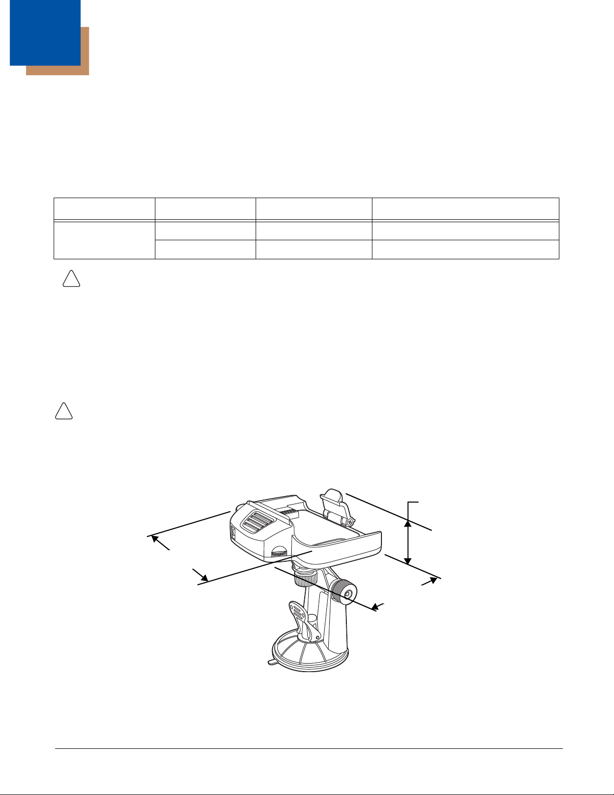
11
!
!
159.98 mm
[6.30 inches]
109.82 mm
[4.32 inches]
42.15 mm
[1.66 inches]
Preliminary Draft, Not for Release - Please Review 2-3-2015
Dolphin 70e Black Mobile Base (Model 70e-MB)
Overview
The Dolphin Mobile Base charging cradle is designed specifically for in-premise and in-transit data collection applications. The
base features a mounting bracket and a cigarette lighter adapter to adapt it to your environment.
The 70e-MB charger is designed for use with the following Dolphin models and batteries manufactured for Honeywell
International Inc:
Dolphin Model Battery Model No. Battery Part No. Battery Specification
Dolphin 75e 70e-BTSC BAT-STANDARD-02 Li-ion 3.7V, 6.179 watt hour
70e-BTEC BAT-EXTENDED-02 Li-ion 3.7V, 12.358 watt hour
We recommend use of Honeywell peripherals, power cables, and power adapters. Use of any non-Honeywell
peripherals, cables, or power adapters may cause damage not covered by the warranty.
Charging Overview
The base provides power to the intelligent battery charging system in all terminals that senses when a full charge has been
achieved and switches to a trickle charge to maintain the full charge. The base completes a full charge of the main battery in 4
hours for the standard battery pack or 6 hours for the extended battery pack.
Note: Before attempting to use, charge, or replace the battery in the terminal, you should read the Guidelines for
Battery Pack Use and Disposal on page 3-11.
We recommend use of Honeywell Li-Ion battery packs. Use of any non-Honeywell battery may result in
damage not covered by the warranty.
Convenient Storage
Intelligent battery charging makes the base a safe and convenient storage receptacle for your Dolphin terminal.
Dimensions
Weight
Mobile Base and adjustable arm weight: 270g [.595 lbs]
11 - 1
Page 92

Mobile Base Components
Terminal Charging Well
Power Adapter
Speaker Volume Control
Spring Latch
Speaker
Power Jack
Mounting Lever
Two point Adjustable
Arm
Suction Cup Base
!
Preliminary Draft, Not for Release - Please Review 2-3-2015
Adjustable Arm with Suction Cup Base for Windshield Mounting
The Mobile Base includes a two point adjustable arm with a suction cup base for fixed mount locations (e.g., a car windshield).
Power Adapter
The mobile base is provided with a power adapter cable that can be connected to a vehicle cigarette lighter outlet.
UL listed power supply
Input: 10V - 30VDC, 0.43A(30V) - 1.28A(10V)
Output: 4.75V - 5.25VDC, 0 - 2A
Verify that the power source is always within the specified range and observe correct input voltage polarity. An
improper input voltage range or reverse polarity could damage the power conversion circuitry.
Speaker and Volume Control Dial
The integrated speaker amplifies the Dolphin terminal’s audio signals and the speaker volume is adjusted using the dial
located on the side of the base.
Spring Latch
The spring latch secures the terminal in the Mobile Base charging well.
Terminal Charging Well
Place the terminal in this well to charge the battery.
11 - 2
Page 93

Mounting the Mobile Base
!
!
!
!
Suction Cup Base
Mounting Lever
Preliminary Draft, Not for Release - Please Review 2-3-2015
Safety Precautions
Honeywell is not responsible for any damages caused to you, your vehicle, or other individuals due to the installation of the
Dolphin Mobile mount. Follow these safety precautions when mounting the mobile base:
Do not mount the base in a location where it prevents safe operation of the vehicle and/or impedes the vehicle
operator's field of view.
Do not mount the base in a location where the connectors on the bottom panel of the base are not easily
accessible. Be sure to leave enough room for unrestricted cable connections.
The Mobile base is intended for use in an enclosed space protected from the elements. Do not mount the
Mobile base on external vehicle surfaces.
Do not install the Mobile base in an air bag deployment zone. Honeywell assumes no responsibility of liability
for injury or death because of car crashes and/or air bag deployment.
Installation
1. Push the suction cup base firmly to the windshield.
2. Flip the mounting lever down to secure the suction cup.
11 - 3
Page 94

3. To adjust the angle of the bracket arm, twist the thumb screws counterclockwise to loosen the locks. Reposition the
Thumb screws for arm angle
adjustments.
5
4
Preliminary Draft, Not for Release - Please Review 2-3-2015
angle of the arm, and then twist the knobs clockwise to lock the arm into position.
4. Insert the power cable connector into the power jack on the Mobile Base.
5. Twist the cable connector 90° clockwise to engage the cable lock.
6. Plug the power adapter into the vehicle power outlet (e.g., cigarette lighter outlet)
Charging the Main Battery
The mobile base provides power to the Dolphin and allows charging of the main batteries in the terminal. The main battery
charges in 4 hours for the standard battery or 6 hours for the extended battery. The intelligent battery charging system
incorporated into all Dolphin terminals prevents overcharging, which means that terminal may be seated in the base indefinitely
without damage to the terminal, battery pack, or the base.
For more information about Honeywell battery packs and how to check battery power levels in your terminal, refer to Battery
(page 3-8).
11 - 4
Page 95

To Power a Terminal and Charge its Main Battery
!
!
Preliminary Draft, Not for Release - Please Review 2-3-2015
Ensure all components are dry prior to mating terminals/batteries with peripheral devices. Mating wet
components may cause damage not covered by the warranty.
We recommend use of Honeywell Li-Ion battery packs. Use of any non-Honeywell battery may result in damage
not covered by the warranty.
1. Install the main battery in the terminal; see Install the Battery on page 2-1.
2. Mount the Mobile base and install the power cable; see Mounting the Mobile Base on page 11-3.
3. Pull the spring latch back and insert the Dolphin 75e into the terminal well. Charging begins immediately if required by
the Dolphin terminal.
Note: Align the contacts on the back panel of the terminal with the charging contacts on the Mobile Base.
11 - 5
Page 96

Removing the Cable
!
1
2
Preliminary Draft, Not for Release - Please Review 2-3-2015
Attempting to remove the cable without disengaging the lock may result in damage
to the base and power cable not covered by the warranty.
1. Twist the cable 90° counterclockwise to disengage the cable lock.
2. Remove the cable from the power jack.
11 - 6
Page 97

12
!
!
Preliminary Draft, Not for Release - Please Review 2-3-2015
Dolphin 70e Black ChargeBase (Model 70e-CB)
Overview
The Dolphin 70e Black ChargeBase is a 4-slot charging cradle that can power four Dolphin terminals, and charge their main
batteries in 4 hours for the standard battery or 6 hours for the extended battery.
The 70e-CB charger is designed for use with the following Dolphin models and batteries manufactured for Honeywell
International Inc:
Dolphin Model Battery Model No. Battery Part No. Battery Specification
Dolphin 75e 70e-BTSC BAT-STANDARD-02 Li-ion 3.7V, 6.179 watt hour
70e-BTEC BAT-EXTENDED-02 Li-ion 3.7V, 12.358 watt hour
We recommend use of Honeywell peripherals, power cables, and power adapters. Use of any non-Honeywell
peripherals, cables, or power adapters may cause damage not covered by the warranty.
Unpacking the ChargeBase
Open the shipping box and inspect the package to see that the following standard items are included:
• One Dolphin ChargeBase, model 70e-CB
• One power supply (see Power on page 12-3)
• One power cord
These items are needed to operate the ChargeBase. If any items are missing or anything appears to be damaged, contact your
Customer Account Representative. Keep the original packaging in case you need to return the ChargeBase for service or to
store the ChargeBase while not in use.
Charging Overview
The base supplies power to the intelligent battery charging system in all Dolphin terminals, which senses when a full charge has
been achieved and switches to a trickle charge to maintain the full charge. As battery packs charge, the charging circuitry
follows the two-step charging process (CC-CV) that is recommended for the battery type. The process monitors changes in
temperature, current, and voltage. The main battery of each terminal charges in 4 hours for the standard battery or 6 hours for
the extended battery.
Note: Before attempting to use, charge, or replace the battery in the terminal, you should read the Guidelines for Battery Pack
Use and Disposal on page 3-11.
We recommend use of Honeywell Li-ion battery packs. Use of any non-Honeywell battery may result in damage
not covered by the warranty.
Convenient Storage
The intelligent battery charging system makes this base a safe and convenient storage receptacle for your Dolphin terminal.
Capacity
The base holds up to four Dolphin terminals. Each charging well charges each terminal independently of the other wells.
12 - 1
Page 98

Dimensions
427.11 mm
[16.80 inches]
98.8 mm
[3.89 inches]
59.75 mm
[2.35 inches]
Dock LED (Qty. 4)
Terminal Wells (Qty. 4)
Preliminary Draft, Not for Release - Please Review 2-3-2015
Weight
ChargeBase weight: 674g [1.49 lbs.]
Note: Weight excludes packaging, cables and power supply.
Parts and Functions
Front Panel
Terminal Wells
The base contains four terminal wells, which offer independent battery charging for each docked terminal.
Dock LEDs
The Dock LED indicates if the terminal is properly seated in the charging well. Each well has a dedicated Dock LED, which
illuminates blue when a terminal is properly seated in the charging well.
12 - 2
Page 99

Back Panel
Power Supply Connector
Serial Number Label
Compliance Label
!
Preliminary Draft, Not for Release - Please Review 2-3-2015
Power Supply Connector
This connector receives input from the power adapter. Plug the power connector cable from the power adapter into this
connector.
Bottom Panel
For details on how to mount the base, see Mounting the ChargeBase on page 12-4.
Power
The terminal requires 12 Volts DC input for battery charging and power output to the terminal. The power adapter included with
the base, converts the voltage from the AC power source to 12 volts DC. Use only a UL Listed power supply, which has been
qualified by Honeywell with output rated at 12VDC and 5 amps with the device. The operating temperature range is -10° to
50°C (14° to 122°F).
Honeywell recommends that you leave the ChargeBase connected to its power source at all times, so that it is always ready to
use.
We recommend use of Honeywell peripherals, power cables, and power adapters. Use of any non-Honeywell
peripherals, cables, or power adapters may cause damage not covered by the warranty.
12 - 3
Page 100

Connecting Power to the ChargeBase
Power Connector Cable
A/C Power Cord
Power Adapter
Power LED
!
!
Preliminary Draft, Not for Release - Please Review 2-3-2015
1. Plug the A/C power cord into the power adapter.
2. Plug the power cable into the power connector on the back of the ChargeBase.
3. Plug the A/C power cord into a grounded power source.
4. The base is ready to begin charging terminals.
Charging the Main Battery
The base provides power to the Dolphin terminals and allows charging of the batteries in the terminals. The battery of each
terminal charges in 4 hours for the standard battery or 6 hours for the extended battery. The intelligent battery charging
system incorporated into all Dolphin terminals prevents overcharging, which means that Dolphin terminals may be seated
in the base indefinitely without damage to the terminals, batteries, or the base.
For more information about Honeywell battery packs and how to check battery power level in your terminal, refer to Battery
(page 3-8).
To Power a Terminal and Charge its Main Battery
Ensure all components are dry prior to mating terminals/batteries with peripheral devices. Mating wet
components may cause damage not covered by the warranty.
1. Install the battery in the terminal, see Install the Battery on page 2-1.
2. Insert the Dolphin terminal into one of the four terminal wells. The Dock LED for the well illuminates blue. Charging
begins immediately if required by the Dolphin terminal.
Note: When the terminal is docked, the Battery Icon changes from to indicating the terminal is running on external
power. Battery charging occurs in the background. When the Dolphin is removed from the base, the battery icon
indicates the charge level of the battery, see Common Status and Notification Icons on page 2-6.
We recommend use of Honeywell Li-ion battery packs. Use of any non-Honeywell battery may result in damage
not covered by the warranty.
Mounting the ChargeBase
Set the base on a dry, stable surface, such as a desktop or workbench near an electrical outlet. Be sure to provide enough
workspace with good lighting for the user to view and operate the Dolphin terminal while it is in the base. When choosing a
location, keep in mind that the mounting location must allow users to see the LEDs and provide easy access to the terminal
wells and the power jack.
12 - 4
 Loading...